Operating principle of a welding inverter
Currently, inverter-type welding machines have become very popular and affordable.
Despite their positive qualities, they, like any other electronic device, sometimes fail.
To repair a welding machine inverter, you need to at least superficially know its structure and main functional blocks.
The first two parts will talk about the design of the welding machine model TELWIN Tecnica 144-164 . The third part will consider an example of a real repair of a welding inverter model TELWIN Force 165 . The information will be useful to all those novice radio amateurs who would like to learn how to independently repair inverter-type welding machines.
There will be a lot of letters further - be patient.
The inverter welding machine itself is nothing more than a fairly powerful power supply. According to the principle of operation, it is very similar to switching power supplies, for example, AT and ATX computer power supplies. You ask: “How are they similar? These are completely different devices...” The similarity lies in the principle of energy conversion.
The main stages of energy conversion in an inverter welding machine:
1. Rectification of alternating voltage 220V;
2. Converting direct voltage to high frequency alternating voltage;
3. Reducing high frequency voltage;
4. Rectification of reduced high-frequency voltage.
This is brief, so to speak, on the fingers. The same transformations occur in switching power supplies for PCs.
The question arises, why do we need these dances with a tambourine (several stages of voltage and current conversion)? And here's the thing.
Previously, the main element of the welding machine was a powerful power transformer. It lowered the alternating voltage of the electrical network and made it possible to obtain huge currents (tens - hundreds of amperes) from the secondary winding, necessary for welding. As you know, if you lower the voltage on the secondary winding of a transformer, you can increase the current that the secondary winding can deliver to the load by the same amount. At the same time, the number of turns of the secondary winding decreases, but the diameter of the winding wire also increases.
Due to their high power, transformers that operate at a frequency of 50 Hz (this is the frequency of the alternating current mains) are very large in size and weight.
To eliminate this drawback, inverter welding machines were developed. By increasing the operating frequency to 60-80 kHz or more, it was possible to reduce the dimensions, and, consequently, the weight of the transformer. By increasing the operating frequency of the conversion by 4 times, it is possible to reduce the dimensions of the transformer by 2 times. And this leads to a reduction in the weight of the welding machine, as well as saving copper and other materials for the manufacture of the transformer.
But where can you get these same 60-80 kHz if the frequency of the alternating current mains is only 50 Hz? This is where the inverter circuit comes to the rescue, which consists of powerful key transistors that switch at a frequency of 60-80 kHz. But for the transistors to work, it is necessary to apply a constant voltage to them. It is obtained from the rectifier. The mains voltage is rectified by a powerful diode bridge and smoothed by filter capacitors. As a result, the output of the rectifier and filter produces a constant voltage of more than 220 volts. This is the first stage of transformation.
This voltage serves as the power source for the inverter circuit. Powerful transistors of the inverter are connected to a step-down transformer. As already mentioned, transistors switch with a huge frequency of 60-80 kHz, and, therefore, the transformer also operates at this frequency. But, as already mentioned, to operate at high frequencies, less bulky transformers are required, because the frequency is no longer 50 Hz, but 65,000 Hz! As a result, the transformer is “shrinked” to a very small size, and its power is the same as that of its hefty brother, which operates at a frequency of 50 Hz. I think the idea is clear.
All this parsley with the transformation has led to the fact that a bunch of all sorts of additional elements appear in the circuitry of the welding machine, which serve to ensure that the device works stably. But enough theory, let’s move on to the “meat”, or rather to the real hardware and how it works.
The design of an inverter-type welding machine. Part 1. Power block.
It is advisable to understand the structure of a welding inverter using the circuit diagram of a specific device. Unfortunately, I did not find a diagram for the TELWIN Force 165 , so we will brazenly borrow the diagram from the repair manual for another device - TELWIN Tecnica 144-164 . Photos of the device and its contents will be from TELWIN Force 165, since it was this one that was at my disposal. Based on the analysis of the circuit design and element base, there are practically no special differences between these models, if you do not take into account the little things.
Appearance of the TELWIN Force 165 welding board indicating the location of some circuit elements.
The schematic diagram of an inverter-type welding machine TELWIN Tecnica 144-164 consists of two main parts: power and control .
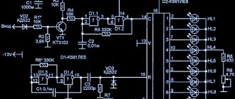
First, let's look at the circuitry of the power section. Here's the diagram. The picture is clickable (click to enlarge - will open in a new window).
Network rectifier.
As already mentioned, first the 220V alternating current is rectified by a powerful diode bridge and filtered by electrolytic capacitors. This is necessary so that the alternating current of the electrical network with a frequency of 50 hertz becomes constant. Capacitors C21, C22 are needed to smooth out the ripples of the rectified voltage, which are always present after the diode rectifier. The rectifier is implemented according to the classic diode bridge circuit. It is made on a PD1 diode assembly.
You should know that the voltage on the filter capacitors will be 1.41 times than at the output of the diode bridge. Thus, if after the diode bridge we get 220V pulsating voltage, then the capacitors will already have 310V DC voltage ( 220V * 1.41 = 310.2V ). Typically, the operating voltage is limited to 250V (the voltage in the network may be too high). Then at the filter output we will get all 350V. That is why capacitors have an operating voltage of 400V, with a margin.
Read also: Wood stitching - what is it?
On the printed circuit board of the TELWIN Force 165 welding machine, the elements of the mains rectifier occupy a fairly large area (see photo above). The rectifying diode bridge is installed on the cooling radiator. Large currents flow through the diode assembly and the diodes naturally heat up. To protect the diode bridge, a thermal fuse is installed on the radiator, which opens when the radiator temperature exceeds 90C 0 . This is an element of protection.
The rectifier uses diode assemblies (diode bridge) of the GBPC3508 type or similar. GBPC3508 assembly is designed for forward current ( I ) – 35A, reverse voltage ( VR ) – 800V.
After the diode bridge, two electrolytic capacitors (big barrels) with a capacity of 680 microfarads each and an operating voltage of 400V are installed. The capacitance of the capacitors depends on the model of the device. In the TELWIN Tecnica 144 model – 470 µF, and in the TELWIN Tecnica 164 – 680 µF. DC voltage from the rectifier and filter is supplied to the inverter.
Noise filter.
To prevent high-frequency interference that occurs due to the operation of a powerful inverter from entering the power grid, an EMC filter - electromagnetic compatibility - is installed in front of the rectifier. In English, the abbreviation EMC is denoted as EMC (ElectroMagnetic Compatibility). If you look at the diagram, the EMC filter consists of elements C1, C8, C15 and a choke on the ring magnetic circuit T4.
Inverter.
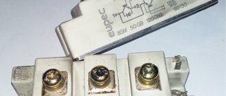
The inverter circuit is assembled according to the so-called “oblique bridge” circuit. It uses two powerful key transistors. In a welding inverter, the key transistors can be both IGBT transistors and MOSFETs. For example, Telwin Tecnica models 141-161 and 144-164 use IGBT transistors ( HGTG20N60A4 , HGTG30N60A4 ), and Telwin Force 165 uses high-voltage MOSFET transistors (FCA47N60F). Both key transistors are installed on the radiator to dissipate heat. Photo of one of two MOSFET transistors type FCA47N60F on the TELWIN Force 165 board.
Let's look at the circuit diagram again and find the inverter elements on it.
The DC voltage is switched by transistors Q5 and Q8 through the winding of the pulse transformer T3 with a frequency much higher than the mains frequency. The switching frequency can be several tens of kilohertz! In essence, alternating current is created, as in the electrical network, but only it has a frequency of several tens of kilohertz and a rectangular shape.
To protect transistors from dangerous voltage surges, damping RC circuits R46C25, R63C30 are used.
To reduce the voltage, a high-frequency transformer T3 is used. Using transistors Q5, Q8, the voltage that comes from the mains rectifier ( DC+ , DC- ). This is the same constant voltage of 310 - 350V that was obtained at the first stage of conversion.
Due to switching transistors, direct voltage is converted into alternating voltage. As you know, transformers do not convert direct current. Much less voltage is removed from the secondary winding of transformer T3 (winding 5-6) (about 60-70 volts), but the maximum current can reach 120 - 130 amperes! This is the main role of transformer T3. A small current flows through the primary winding, but a large voltage. A small voltage, but a large current, is already removed from the secondary winding.
The dimensions of this transformer are small.
Its secondary winding is made of several turns of copper tape wire insulation. The cross-section of the wire is impressive, and no wonder, the current in the winding can reach 130 amperes!
Next, high-frequency alternating current is rectified from the secondary winding of the pulse transformer by powerful diode rectifiers. Electric current with the required parameters is removed from the rectifier output (OUT+, OUT-). This is necessary for welding work.
Output rectifier.
The output rectifier is assembled on the basis of powerful dual diodes with a common cathode (D32, D33, D34). These diodes have high speed, i.e. they can open quickly and close just as quickly. Recovery time trr of your page –>
Welding is the most popular joining method, which can exist in several variants. The most popular technology is considered to be welding using the inverter method. Despite the high quality of the welding inverter, it happens that due to one reason or another, it becomes faulty. This may require its owner to carry out repairs.
Review of IGBT series from ST
The IGBT line produced by STMicroelectronics contains four series, the representatives of which are most suitable for welding inverters. These are the V, HB, H, M series. All these transistors meet the above requirements and have excellent characteristics [1, 4]:
The M series is designed for switching voltages up to 1200 V and currents up to 40 A (Table 2). A distinctive feature of the series is its low saturation voltage (no more than 2.2 V) and low switching energy (from 1.2 mJ). This makes these transistors the optimal choice for inverters operating at frequencies up to 20 kHz.
Table 2. Characteristics of M-series IGBTs
| Name | Frame | Uke max., V | Ik max. at Tc = 100°C, A | Uke us. max., V | Eoff typ. at Tc = 125°C, mJ | Diode | Fmax, kHz | Pd max., W |
| STGW15M120DF3 | TO-247 | 1200 | 15 | 2,2 | 1,2 | There is | 20 | 283 |
| STGW25M120DF3 | TO-247 | 1200 | 25 | 2,2 | 2 | There is | 20 | 326 |
| STGW40M120DF3 | TO-247 | 1200 | 40 | 2,2 | 3 | There is | 20 | 468 |
| STGWA15M120DF3 | TO-247 LONG LEADS | 1200 | 15 | 2,2 | 1,2 | There is | 20 | 283 |
| STGWA25M120DF3 | TO-247 LONG LEADS | 1200 | 25 | 2,2 | 2 | There is | 20 | 326 |
| STGWA40M120DF3 | TO-247 LONG LEADS | 1200 | 40 | 2,2 | 3 | There is | 20 | 468 |
The H series is capable of switching voltages up to 1200 V and currents up to 40 A (Table 3). Compared to M-series transistors, H-series IGBTs have lower switching energy (from 0.85 mJ) and higher saturation voltage (up to 2.4 V). For this reason, they are suitable for higher frequency applications and are capable of operating at frequencies up to 100 kHz.
Table 3. H Series IGBT Specifications
| Name | Frame | Uke max., V | Ik max. at Tc = 100°C, A | Uke us. max., V | Eoff typ. at Tc = 125°C, mJ | Diode | Fmax, kHz | Pd max., W |
| STGW15H120DF2 | TO-247 | 1200 | 15 | 2,4 | 0,85 | There is | 50 | 260 |
| STGW15H120F2 | TO-247 | 1200 | 15 | 2,4 | 0,85 | No | 50 | 260 |
| STGWA15H120DF2 | TO-247 LONG LEADS | 1200 | 15 | 2,4 | 0,85 | There is | 50 | 260 |
| STGWA15H120F2 | TO-247 LONG LEADS | 1200 | 15 | 2,4 | 0,85 | No | 50 | 260 |
| STGW25H120DF2 | TO-247 | 1200 | 25 | 2,4 | 1,4 | There is | 50 | 375 |
| STGW25H120F2 | TO-247 | 1200 | 25 | 2,4 | 1,4 | No | 50 | 375 |
| STGW40H120DF2 | TO-247 | 1200 | 40 | 2,4 | 2,2 | There is | 100 | 468 |
| STGW40H120F2 | TO-247 | 1200 | 40 | 2,4 | 2,2 | No | 100 | 468 |
The HB series is not the main one for the construction of welding inverters, but its characteristics are also excellent (Table 4). The saturation voltage for these IGBTs is a record among all families and starts from 1.65 V. Switching energy, in many cases, does not exceed 0.6 mJ. The operating frequency for members of the family reaches 50 kHz.
Table 4. HB Series IGBT Specifications
| Name | Frame | Uke max., V | Ik max. at Tc = 100°C, A | Uke us max., V | Eoff typ. at Tc = 125°C, mJ | Diode | Fmax, kHz | Pd max., W |
| STGFW20H65FB | TO-3PF | 650 | 20 | 1,65 | 0,6 | No | 50 | 58 |
| STGFW30H65FB | TO-3PF | 650 | 30 | 1,65 | 0,6 | No | 50 | 58 |
| STGFW40H65FB | TO-3PF | 650 | 40 | 1,8 | 0,6 | No | 50 | 58 |
| STGW20H65FB | TO-247 | 650 | 20 | 1,65 | 0,6 | No | 50 | 260 |
| STGW30H65FB | TO-247 | 650 | 30 | 1,65 | 0,6 | No | 50 | 260 |
| STGW40H65DFB | TO-247 | 650 | 40 | 1,8 | 0,6 | There is | 50 | 283 |
| STGW40H65FB | TO-247 | 650 | 40 | 1,8 | 0,6 | No | 50 | 283 |
| STGW60H65DFB | TO-247 | 650 | 60 | 1,75 | 1 | There is | 50 | 375 |
| STGW60H65FB | TO-247 | 650 | 60 | 1,75 | 1 | No | 50 | 375 |
| STGW80H65DFB | TO-247 | 650 | 80 | 1,6 | 1,3 | There is | 50 | 469 |
| STGW80H65FB | TO-247 | 650 | 80 | 1,8 | 1,9 | No | 50 | 469 |
| STGWA80H65FB | TO-247 LONG LEADS | 650 | 80 | 1,8 | 1,9 | No | 50 | 469 |
| STGWT20H65FB | TO-3P | 650 | 20 | 1,65 | 0,6 | No | 50 | 260 |
| STGWT30H65FB | TO-3P | 650 | 30 | 1,65 | 0,6 | No | 50 | 260 |
| STGWT40H65DFB | TO-3P | 650 | 40 | 1,8 | 0,6 | There is | 50 | 283 |
| STGWT40H65FB | TO-3P | 650 | 40 | 1,8 | 0,6 | No | 50 | 283 |
| STGWT60H65DFB | TO-3P | 650 | 60 | 1,75 | 1 | There is | 50 | 375 |
| STGWT60H65FB | TO-3P | 650 | 60 | 1,75 | 1 | No | 50 | 375 |
| STGWT80H65DFB | TO-3P | 650 | 80 | 1,6 | 1,3 | There is | 50 | 469 |
| STGWT80H65FB | TO-3P | 650 | 80 | 1,8 | 1,9 | No | 50 | 469 |
Brief information about inverters for welding
The inverter serves as a source of direct current, which helps ignite and maintain the electric arc that powers the welding process.
The welding process is carried out thanks to a welding current of considerable strength resulting from the operation of a high-frequency transformer.
This fact makes it possible to reduce the size of the transformer itself, increases stability and precise regulation of the output current.
Welding activities are carried out in the presence of a current of the required magnitude, which is obtained in several stages: • Initially, the current received from the network is rectified; • Transform primary current of constant value into high-frequency current; • They increase the current and at the same time reduce the voltage in the transformer itself; • The output current is rectified for the second time.
Current rectification occurs thanks to diode bridges of a given power. Special transistors help to correctly change the frequency of the current, providing high-frequency transformers with the required output current.
Structure
Inverters for welding activities are represented by several blocks. The power supply itself is responsible for the stability of the output signal.
The multi-winding inductor, the control performed by transistors, as well as the concentration of energy in the capacitor itself are fundamental factors in the control circuit of the unit. As a rule, diodes are involved in throttle control. The power supply is a separate element, separated from other components by a metal partition.
The main element in inverter welding equipment is the power unit. It converts the primary current coming from the power supply into an output current that is directly used for welding.
An electric current of no more than 40A is supplied to the diode bridge, which serves as the primary rectifier. In this case, the voltage fluctuates between 200-250V and a given frequency of 50 Hz.
Read also: How to connect a light bulb through a switch and socket
The inverter converter itself has the form of a power transistor with a power of less than 8 kW, while the voltage is 400 V. The signal itself, which is obtained at the output of the converter, has a frequency of 100 kHz.
The increase in current strength to 200-250A occurs due to the tape windings with which the high-frequency transformer is equipped. With the secondary winding, the voltage readings are no more than 40V.
The secondary rectifier is made up of diodes with a current strength above 250A. Its cooling occurs due to the presence of certain elements, namely: • Fans; • several radiators. To ensure a stable output signal, a choke is mounted on the output board.
Control units As a rule, the basis of the control unit itself is represented by a master oscillator (in other words, a wide-pulse modulator). If there is a circuit based on the generator itself, a microcircuit can be used. 6-10 capacitors and a working resonant choke are also concentrated on the plateau. Thanks to the transformer, a cascade type of control is carried out.
Most inverters have a protection circuit, which is located on a plateau in the power unit. Excellent protection against excessive overloads is provided by the circuit, which is based directly on the 561 LA 7 type microcircuit.
Resistors and specified capacitors K78-2 serve as the basis for snubbers, which are used in the protective system of converters and rectifiers. The presence of a thermal switch provides high-quality protection of all components in the power unit.
Long-term use of even a high-quality inverter can lead to malfunctions. Breakdowns can occur due to various reasons. For example, due to short circuits in electrical circuits caused by moisture.
Sometimes malfunctions can be caused by the welder’s attempts to perform work that is unacceptable on this equipment.
Review of powerful W series diodes from ST
Powerful high-speed diodes of the W series are designed specifically for operation as part of high-power pulse converters with harsh switching conditions. For this purpose, their characteristics are optimized accordingly (Table 7):
Table 7. Powerful high-speed diodes produced by STMicroelectronics
| Name | Frame | Diodes in the housing | Urev max., V | Iav max., A | Udirect max. at current, V | trestore max., ns | Tcrystal max., °C |
| STTH20W02C | TO-247 | 2 | 200 | 10 | 1.05 (10 A) | 25 | 175 |
| STTH30W02C | TO-247 | 2 | 200 | 15 | 1.15 (15 A) | 27 | 175 |
| STTH60W02C | TO-247 | 2 | 200 | 60 | 0.92 (30 A) | 30 | 175 |
| STTH200W03TV1 | ISOTOP | 2 | 300 | 200 | 1.15 (100 A) | 50 | 150 |
| STTH60W03C | TO-247 | 2 | 300 | 30 | 1.15 (30 A) | 35 | 175 |
| STTH30W03C | TO-247 | 2 | 300 | 15 | 1.4 (15 A) | 25 | 175 |
| STTH200W04TV1 | ISOTOP | 2 | 400 | 200 | 1.55 (100 A) | 55 | 150 |
| STTH61W04S | TO-247 | 1 | 400 | 60 | 1.15 (30 A) | 55 | 175 |
| STTH100W04C | TO-247 | 2 | 400 | 100 | 1.2 (50 A) | 50 | 175 |
| STTH200W06TV1 | ISOTOP | 2 | 600 | 200 | 1.3 (100 A) | 75 | 150 |
| STTH100W06C | TO-247 | 2 | 600 | 100 | 1.15 (50 A) | 75 | 175 |
| STTH50W06S | TO-247 | 1 | 600 | 50 | 1.75 (50 A) | 45 | 175 |
Malfunctions and their options
Blowing of the fuses themselves can lead to a situation where there is no output current to the inverter, while the proper voltage is available at the input.
A breakdown can also result from a violation of the overall integrity of the electrical circuit, which can occur in any part of the inverter. Another possible malfunction is represented by low welding current readings, despite the highest settings. This situation may arise due to insufficient voltage at the input or due to losses in the contact terminals themselves.
Frequent independent shutdowns of the welding inverter may indicate a short circuit in the electrical network.
Overheating of the components of the power unit can lead to the same effect. In this situation, the protection system may be triggered, which leads to an emergency shutdown.
Carrying out repair activities and their order
If any breakdown is detected, first of all, you should begin an external inspection of the equipment, during which a professional can detect various damage or burns due to a short circuit. Then check the reliability of the electrical cables in the terminals.
Regardless of the inspection results, it is necessary to tighten the cable clamps, for which they use a wrench or a screwdriver. It is advisable to check the integrity of absolutely all fuses using a special tester.
If there is no effect from the previous actions, you need to remove the cover from the inverter housing and inspect the internal contents of the equipment in search of a possible open circuit or traces of a short circuit.
To speed up the identification of the cause of the breakdown, you should measure the output voltage and input current using a multimeter or tester.
If there is no visual damage to the equipment, a unit-by-unit electrical circuit integrity check should be performed. In such a situation, the power supply unit is inspected first, and then the other units.
Soft start
To power the inverter control unit, a stabilizer is used on a microcircuit with a radiator. The supply voltage comes from the main rectifier through a resistive divider.
When the welding inverter is turned on, the capacitors begin to charge. The currents reach such high values that they can burn out the diodes. To prevent this from happening, a charge limiting circuit is used.
At the moment of starting, the current passes through a powerful resistor, which limits the starting current. After charging the capacitors, the resistor is switched off and shunted using a relay.
Power unit and its repair
High-quality repair of faults is possible only if you have a certain set of tools and measuring instruments, namely: • 40V soldering irons; • Knives; • Pliers; • Nippers; • Ammeters for 50 and 250A; • Oscilloscope; • Voltmeters for 50V and 250V; • Soldering irons 40V; • Wrench and socket wrench.
When testing the control unit and power unit, special attention should be paid to their elements. A typical breakdown of the power unit is the breakdown of the power transistor, which means that it is advisable to start looking for problems by inspecting it.
Workflow Technology
The presence of mechanical damage on the surface of the transistor may indicate possible damage. The absence of these leads to testing with a multimeter. The transistor malfunction can be eliminated by replacing it with a new device. What is KPT-8 thermal paste used for, which is needed to install it on the plateau.
If the transistor fails to operate, the cause must be sought in a driver failure. Evaluate the operation of these control transistors using an ohmmeter. If non-working parts are found, they are unsoldered and replaced with new ones.
Diode bridges of rectifiers are considered the most reliable in the design of welding inverters, however, this situation cannot be completely eliminated.
When troubleshooting a diode bridge, it is necessary to remove it from the plateau and test its performance by connecting all the diodes together. If the resistance readings are close to zero, then you need to look for a specific faulty diode. Its detection leads to replacement with a new element.
When identifying breakdowns in the control unit, it is necessary to check the parameters of the parts that produce various complex signals. In this case, problems may arise in diagnostics using an oscilloscope, which will require the participation of an experienced specialist.
The reason for the lack of automatic shutdown of the inverter when parts in the power unit are severely overheated may be a malfunction of the thermal switches. To eliminate problems, first of all, you should check the quality of their attachment to the parts on which they carry out temperature control. If one of the thermal switches does not work, it must be replaced with a new one.
Welding inverters serve as the main equipment for professional welders. However, even ultra-modern equipment can fail and require high-quality repairs.
Independent troubleshooting of minor problems is possible if you have basic knowledge of electrical engineering and the necessary tools needed to correctly detect breakdowns. Accurate diagnosis of the causes of malfunctions will help reduce the time to eliminate them to a minimum.
Welding technology has firmly and confidently entered our lives, and without high-quality joining of the surface of metal products it is impossible to imagine our life. The abundance of welding technologies makes it possible to put inverter technology in first place, where high quality welds and connections can be achieved. Power transistors for welding inverters are rightly called the heart of the device. The correct choice of device depends on the effective calculation of power and other technical characteristics of the welding device.
Read also: Power control on a triac
Which is better MOSFET or IGBT?
Some companies keep up with the times and in the production of welding inverters use American IGBT transistors, the switching frequency of which is 50 kHz, i.e. 50,000 times per second. IGBT technology was chosen for a reason, because their operating temperature range, while maintaining parameters, is much greater than that of MOSFETs, i.e. when heated, MOSFETs’ quality characteristics decrease.
The design of SAI (Resanta) uses one small board, which is installed vertically, as well as 4 IGBT transistors (they work separately from each other, i.e. they all do not burn out if one burns out like a MOSFET) and 6 rectifier diodes (not 12 like a MOSFET), respectively, the fault tolerance is lower. This is another “plus” of IGBT.
You can remind the buyer that modern welding inverters use only 4 individual transistors, and not 12 cascade-dependent ones like MOSFETs. Anything can happen in life, but no matter what happens if one transistor fails (if not a warranty case), a replacement will cost the buyer somewhere in the region of 400 rubles, and not 12 × 110 rubles. = 1320 rub. I think the difference is significant.
How to distinguish: Visually, IGBT devices mostly differ from MOSFETs in the vertical arrangement of power connectors, since there is only one board and is usually installed vertically. For MOSFET devices, the outputs are usually located horizontally, since the boards in the structure are horizontally fixed. It is impossible to say for sure that this is 100% true. More precisely, you can say by removing the casing from the device.
Many are transistorized. For example, it has currently launched devices on the market (using MOSFET technology) with stickers on the side panels “TOSHIBA transistors are used” and “Mitsubishi transistors are used.” They are trying to crawl out on loud and familiar brands. In practice this has not been confirmed. So at the largest International Tool Exhibition in Russia, Moscow International Tool Expo (MITEX-2011), which took place in November 2011. at Expocentre (Moscow), I asked representatives of this company’s stand to disassemble their AIS with the sticker “Mitsubishi transistors are used” and demonstrate these transistors. As a result, the welding inverters were disassembled, but these transistors were not found. The employees themselves were shocked to discover unnamed transistors.
Source
What is an inverter, and the correct choice of main components and components
To understand what transistors are used in welding inverters, you need to know the structure and operating principle of inverter equipment. An inverter in a broad sense is a universal source of direct current that ensures the process of igniting the arc and maintaining optimal operating mode. Welding is carried out by supplying a significant current to the device, due to the high-frequency transformer introduced into the design. In this case, you can use a smaller version of the transformer, and increase the stability and effective current regulation mode, which is ensured by introducing an IGBT transistor for the welding inverter.
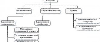
Today, the welding equipment market is represented by various equipment options that have unique properties and operating principles, which ultimately determine why the transistors burn in the welding inverter. Currently, welding inverter options are represented by the following units:
- Manual welding with consumable electrodes, manual metal arc series, MMA. Manual welding equipment operating in a protective gas environment tungsten inert gas, TIG. Semi-automatic welding technology using inert gases, standard design - metal inertgas, MIG. Welding devices based on the work of active gases such as metal active gas, MAG.
- Welding units with an inverter operating principle - transformer devices, as well as completely inverter equipment.
- Units with a constant mode of output current supply, for example, for welding steel metals, as well as with a variable mode of operation, for example, for soldering aluminum or cast iron.
As you can see, each type of equipment has its own operating conditions and, therefore, it is necessary to select imported and domestic brands of transistors for welding inverters, and sometimes in the appropriate combination.
“Please note! Most often, inverter units that operate on the MMA principle are used.”
These types of devices are unpretentious and have proven themselves both in private households and in production areas.
Results of practical application of IGBT from ST in MMA inverters
To confirm the advantages of IGBT transistors manufactured by STMicroelectronics, welding inverters were built and tested: MMA160 (input power 3.8 kW) and MMA200 (input power 6 kW) [3].
The test conditions were the same [3]:
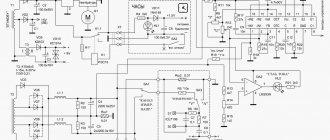
The MMA160 inverter was built on the basis of STGW40V60DF transistors (Figure 5). The switching frequency was 63 kHz.
Rice. 5. MMA160 inverter circuit
During the tests, measurements were taken of input power, input current and transistor housing temperature. When the input power increased from 2 kW to a maximum power of 3.8 kW, the transistors warmed up and the turn-off energy increased (Table 8).
Table 8. Test results of the MMA 160 inverter
3.8 (max)
| Input power, kW | Input current, A | Power factor | Temperature, °C | Time | Switch-off energy, mJ |
| 2 | 15,4 | 0,58 | 62 | – | 311 |
| 3 | 22,2 | 0,61 | 83 | – | 466 |
| 26,3 | 0,66 | 105 | 10 min 17 sec | 550 |
The inverter showed stable operation over the entire power range. The shutdown at maximum power occurred only after 10 minutes 17 seconds, after the overheating protection (105°C) was activated. The maximum energy value for turning off the IGBT increased from 311 mJ to 550 mJ, which is a good result and corresponds to the value stated in the documentation (Table 5).
The MMA200 inverter was built using twin STGW60H65DFB IGBTs (Figure 6). The operating frequency was 63 kHz. For additional protection of transistors, snubber RC circuits were used.
Rice. 6. MMA200 inverter circuit
During testing, the MMA200's input power was increased from 2.6 kW to 5.8 kW. The inverter demonstrated stable operation in all modes and turned off after the temperature protection was activated 8 minutes 15 seconds after reaching a power of 5.8 kW. As the input currents increased, the transistor temperature increased and the turn-off energy increased (Table 9). The range of energy changes during shutdown was 586...947 mJ, which corresponds to the declared value.
Table 9. MMA200 inverter test results
4624
| Input power, W | Output current, A | Output power, W | Temperature, °C | Time | Switch-off energy, mJ |
| 105 | 8 min 15 sec | 947 |
The tests carried out confirmed the excellent characteristics declared by the manufacturer. Thus, IGBTs manufactured by STMicroelectronics are ideal for building inverters for welding machines.
Technical components
The general structure of operation of such a device is simple, and includes a main current source, an optional rectifier element for the output current, and a common control unit.
A high-quality current source can be completely implemented on the basis of transformer technology or solely on the basis of an inverter system, where power transistors for welding inverters play an important role in the high-quality performance of the device.
For transformer installations, independent manual regulation of the operation of the device is allowed, but among the disadvantages are the rough adjustment mode and the low level of quality of the weld. Inverter installations, on the contrary, having the simplest welding inverter on a single transistor provide high quality weld formation, which is combined with power semiconductor elements.
The main technical components that ensure high quality welding work are the presence of IGBT transistors, as well as universal high-speed diodes. In this case, a reasonable question arises: how to check the IGBT transistor of a welding inverter. We indicate the basic data of transistor components for welding the IGBT version
Ultra-low shutdown energy, operation up to 600 V, frequency up to 1200 kHz
Low voltage saturated impact principle. Low shutdown energy. Voltage up to 650 Volts, frequency up to 50 kHz
Low effect of shutdown mode. Supply voltage - up to 1200 volts, frequency up to 35 kHz.
Low voltage saturation mode, mains voltage up to 1200 Volts, frequency parameter - up to 20 kHz
Low forward voltage drop mode, and minimal recovery effect mode.
Features of operation of transistor units
The most common application scheme inside inverters is used using push-pull technology, a bridge operating principle, a half-bridge version of a working inverter, a half-bridge complex asymmetric version of an inverter device, or an oblique half-bridge. Despite the sufficient abundance of topologies, replacing the FGH40N60 transistor in a welding inverter according to general requirements is standard, which includes the following:
- High voltage mode. To effectively replace transistors in welding inverters, the total network voltage must be above 600 Volts.
- Large parameters of switching currents. The average value of the indicator should be at least tens of amperes, and the maximum parameters can show hundreds of amperes.
- High frequency switching mode. Depending on the dimensions of the transformer inside the device, you can increase the frequency of the device, as well as the inductance for the output filter model.
- For the mode of minimizing losses when turning the unit on and off, you can find out how to check the transistors of the welding inverter using a small value of energy supply to the on mode (Evkl), as well as to the shutdown mode (Eukl). In this case, all losses will be minimized.
- To minimize possible losses, we use a low value for the saturation voltage, or Uke us.
- The hard switching effect must be stable for transistors for Resanta welding inverters. In this case, inverter equipment only works with inductive load mode.
- Short circuit parameters. The device must have a resistance mode for this parameter; this information is extremely critical for bridge and half-bridge versions of inverter technology.
How to calculate power loss on IGBT?
We recommend using the diagram below for a detailed calculation of the correct choice of transistor systems.
| Options | Values |
| Total losses | Pd = Pcond + Pswitch |
| Conducted losses | Pcond = Uke us (rms) × Ik × D, where D is the duty cycle |
| Switching losses | Pswitch = Eswitch × f, where f is the switching frequency, Eswitch = (Eon + Eoff) - the total switching losses (given in the IGBT parameters) |
| Maximum power limited by chip overheating | Pd = (Tj – Tc)/Rth-jc, where Tc is the case temperature, Tj is the crystal temperature, Rth-jc is the “chip-to-case” thermal resistance (given in the IGBT parameters) |
All this data will help you correctly calculate the required type of transistor for an inverter welding machine. When choosing a transistor, we must take into account the parameter for the high threshold of the possible operating voltage of the device.
MOSFET or IGBT?
Let's look at the differences in general first. Currently, all inverter manufacturers (MMA) are produced using two semiconductor technologies: IGBT and MOSFET. I will not go into details, I will only say that the circuit design of these devices uses different semiconductor transistors IGBT and MOSFET. The main difference between these transistors is the different switching current. IGBT transistors have high current.
To make a standard inverter, you will need 2–4 IGBT transistors (depending on the duty cycle), and MOSFETs - 10–12, because they cannot pass large currents through themselves, so they have to be divided into such a large number of transistors. That's actually the difference.
The subtlety is that the transistors get very hot and need to be installed on powerful aluminum radiators. The larger the radiator, the greater the heat removal from it, and, consequently, its cooling capacity. The more transistors, the more cooling radiators need to be installed, therefore, the dimensions, weight, etc. increase. MOSFET definitely loses here.
In practice, MOSFET circuitry does not allow creating a device on one board: that is, the devices that are currently on sale are assembled mainly on three boards. IGBT devices always come on the same board.
Mechanical damage to modules
a) Installation of the module on the cooler
The IGBT module has solder connections between semiconductor chips, boards and the base. In this regard, significant mechanical stress on the housing or base of the module can lead to cracks in the crystals of transistors and diodes. In addition, the design of the modules uses parts made of fragile materials (ceramics Al2O3 or AlN, composite material AlSiC), so the modules must be handled with care, especially after unpacking from shipping containers. It is prohibited to drop the modules or cause any blows to the body or base. Concentrated impacts on the base of the module and on the cooler with modules attached to it are especially dangerous. The shock wave is transmitted from the cooler to the base, as a result of which conditions are created for the appearance of cracks in the crystals and boards of the module.
To reduce the transient thermal resistance, the cooling modules of the module bases of many manufacturers have a convex shape. Before attaching the module to the cooler, a thin layer of heat-conducting paste is applied to the base, which fills the voids, displacing air. The paste layer must have a minimum thickness, since its thermal conductivity is still relative.
When attaching the module to the cooler using screws, the base is pressed against the cooler with considerable force, so all the excess applied paste is squeezed out. The use of pastes with very high viscosity can lead to unacceptable bending of the copper base and the appearance of cracks in metal-ceramic boards and crystals when mounting the module to a cooler. The photograph (Fig. 9) shows a crack on the IGBT crystal, which appeared as a result of mounting the module on a cooler using KPT-8 heat-conducting paste. The paste had a thick consistency, was applied in a thick layer and during installation was practically not squeezed out from under the module, as a result of which unacceptable deformation of the base and mechanical destruction of one of the crystals occurred. When a voltage was subsequently applied to the module, a point breakdown occurred along the crack, the location of which is also clearly visible in the photograph.
Rice. 9. A crack in the IGBT crystal resulting from a module fracture when using high-viscosity thermal conductive paste
According to the results of studies carried out at JSC Elektrovypryamitel, the best results during the installation and operation of IGBT modules were shown by HTC heat-conducting paste from Electrolube.
b) Installation of power buses
Installation of power buses to IGBT modules must be carried out in strict compliance with the assembly technology, as well as taking into account the requirements for the design and properties of power buses. The power terminals of the modules have internal dampers, which are designed to compensate for differences in the temperature coefficients of expansion of parts and virtually eliminate mechanical loads in the soldered contacts that arise when installing external busbars. However, exceeding the permissible mechanical loads on the terminals during installation can lead to damage to the device.
External power bars are usually made of solid copper and have high rigidity. If there are large gaps between the module pins and the bus, there is a possibility of severe deformation of the pins and disruption of the internal contact in the module.
In our practice, there have been cases when a consumer, using transistor and diode modules of different heights, connected them with rigid buses (Fig. 10). The gap between the power bus and the output of the central module was ~3 mm.
Rice. 10. Example of incorrect installation leading to separation of the power terminal of module 2
In this case, when tightening the mounting screws, simultaneously with the elastic bending of the power bus, the lead from the housing of module 2 is pulled out, which leads to a break in the power lead inside the module.
Also, modules should not be used as supports for fastening massive power busbars, especially taking into account shock and vibration loads. The best solution would be to mount the power busbars on special insulator supports, which take on the main mechanical load.
Summarize
Many of the above facts relate to the historical basis of both devices. Advances and technological breakthroughs in the development of new equipment, as well as the use of new materials such as silicon carbide (SiC), have led to significant improvements in the performance of these radio components in recent years.
In any case, MOSFET and IGBT modules are quickly replacing most older semiconductor and mechanical devices used for current control. SiC-based power devices demonstrate advantages such as lower losses, smaller size and higher efficiency. Innovations like these will continue to push the limits of using MOSFETs and IGBTs for higher voltage and higher power applications.
Source