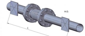
Fig.1 Inter-support rotor
Fig.2 Cantilever rotor
Fig.3 Double-cantilever rotor
In order for the rotor to be balanced, it is necessary and sufficient that the axis of rotation of the rotor passes through its center of mass (e st
= 0).
(static balance) and that the axis of rotation of the rotor coincides with one of its main axes of inertia, i.e., so that its centrifugal moments of inertia are equal to zero (momentary balance). Static balance + moment balance = dynamic balance. Unbalance
is a condition of the rotor characterized by a distribution of masses that, during rotation, causes variable loads on the rotor supports and its bending.
The measure of imbalance is considered to be imbalance D.
To compare rotors of different masses,
a specific imbalance is introduced,
numerically equal to
ect = D / mp
.
where D is the imbalance, mp is the rotor mass.
Thus, the imbalance D is measured in g*mm (unbalanced mass x radius), and the specific imbalance is measured in microns - g*mm/kg= mm/1000= µm.
Fig.4 Main vector and main moment of rotor imbalance.
The unbalance unit is gram-millimeter (g mm) and degree (...°), which measure the unbalance value and the unbalance angle, respectively. The ratio of the module of the main imbalance vector to the rotor mass characterizes the specific imbalance [(g mm)/kg = µm]. All rotor imbalances are reduced to two vectors - the main vector Dst and the main moment Md of imbalances, regardless of the reasons that caused the center of mass to shift from the axis of rotation: errors in obtaining the workpiece, errors in mechanical assembly production, or changes in operating conditions. The main vector of imbalances Dst passes through the center of mass and is equal to the product of the mass of the unbalanced rotor by its eccentricity e. The main moment of imbalances Md is equal to the geometric sum of the moments of all imbalances of the rotor relative to its center of mass. The main moment of unbalances is perpendicular to the main central axis of inertia and the axis of the rotor and rotates with the rotor. The main vector of imbalances in the planes of supports can be replaced by its components (symmetrical imbalances). The main moment of imbalances in the same planes of supports can be replaced by a pair of forces (obliquely symmetrical imbalances).
The unbalance is a vector quantity and is completely determined on the rotor in the selected plane by the angle of unbalance, as well as the numerical value of the unbalance Di = miei, i.e., the product of the unbalanced mass mi by the modulus of its eccentricity ei relative to the axis of rotation. This plane can be used to set the imbalance (imbalance reduction plane), adjust the rotor masses (correction plane), and measure the imbalance (imbalance measurement plane). The imbalances in different two planes along the axis of a given rotor are different, and their angles and values can be found by calculation, as well as using balancing equipment.
The structure of the balancing technological process is determined by the purpose of balancing, type of production, size of the part or assembly unit, balancing accuracy, technological equipment and tooling, etc.
Balancing involves determining the values and angles of rotor imbalances and reducing them by adjusting the rotor mass.
The effect of unbalances on the rotor can be reduced or eliminated by adding, reducing or moving one or more correction masses creating an unbalance of the same value as the unbalanced rotor, but with an unbalance angle of 180° relative to the rotor unbalance.
Methods for eliminating rotor imbalances.
To reduce rotor imbalances, so-called correction masses are used, which can be removed from the rotor body or added to it.
Corrective mass is added in antiphase to the rotor imbalance by welding, riveting, soldering, screwing in special elements of a certain mass and at a certain radius. There are imbalances: initial - before adjusting the masses, residual - after adjusting the masses, permissible - acceptable according to the operating conditions of the machines, specific - the ratio of the module of the main vector to the mass of the rotor. There are static (force), moment and dynamic (torque-force) balancing. During static balancing, the main vector of imbalances is determined and reduced, i.e. the center of mass of the rotor is brought to the axis of rotation by placing the corresponding corrective mass (mass). With moment balancing, the main moment of imbalance is determined and reduced by forming a pair of forces by placing corrective masses in two correction planes. In this case, the main central axis of inertia of the rotor as a result of rotation is aligned with the axis of rotation. During dynamic balancing, the main moment and the main vector are determined and reduced. This is achieved by placing correction masses in two (rigid rotors) or more correction planes (flexible rotors). In this case, the main central axis of inertia is displaced, rotated in space and aligned with the axis of rotation of the rotor. The rotor can be balanced in one or more operations consisting of typical steps; identification and determination of the value and angle of imbalances (measuring), and correction (elimination) of imbalances to specified values.
Balancing machines.
A balancing machine is a mechanical device designed to determine and eliminate the imbalance of individual rotors. It usually consists of supports in which the rotor to be balanced is placed, a drive for its rotation and a measuring device with indicating instruments. Unlike balancing the rotor at its standard installation location, the rotor is mounted on supports that are part of the balancing machine structure, and the balancing machine drive is used to drive the rotor into rotation. The forces arising during the rotation of an unbalanced rotor cause vibrations in the mechanical rotor-support system, which are measured by the built-in measuring system of the machine.
By the nature of the operating mode and design, the most widely used balancing machines are pre-resonance
and
over-resonance
type.
In a pre-resonant balancing machine, the rotation frequency is lower than the natural frequency of oscillation of the system, consisting of the rotor being balanced and part of the machine mass participating in the oscillations.
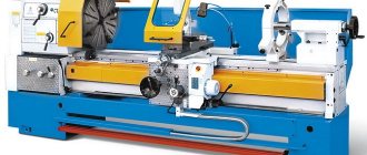
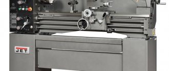
Fig.5 The TB-500 pre-resonance balancing machine allows balancing rotors weighing up to 500 kg and a maximum distance between journals of up to 2000 mm.
In a resonant balancing machine, the rotor rotation frequency during balancing is significantly higher than the highest natural frequency of oscillation of the rotor system.
Depending on the type of machine, they are equipped with flexible
or
rigid
supports.
Classification of balancing machines.
A balancing machine is essentially a vibration meter of the mechanical system associated with the rotor, the characteristics of which indicate the unbalance of the rotor.
Some machines may have built-in devices for adjusting rotor masses. In serial and mass production, the operations of determining and reducing imbalances can be combined, i.e. measurements of rotor imbalances and correction of its masses are carried out simultaneously.
Based on the nature of the operating mode and design, balancing machines of pre-resonant, resonant and post-resonant types are distinguished.
In a pre-resonance balancing machine, the rotation frequency during balancing is lower than the lowest natural frequency of oscillations of the system, consisting of the rotor being balanced and the parasitic mass, which includes part of the mass of the machine involved in oscillations when they are excited by unbalanced forces of the rotor.
In a resonant balancing machine, the rotation frequency in a steady-state balancing mode is equal to the natural frequency of oscillation of the system consisting of a rotor and a balancing mass. This also includes machines with balancing when passing through the resonant mode. Machines with passage through resonance are the simplest, have a simple drive and allow vibration amplitudes to be measured with simple instruments, but have uncertain characteristics when passing through the resonance mode, which reduces the balancing accuracy.
Machines operating in resonant mode are more sensitive, but require the use of a complex drive to strictly maintain this mode.
In a resonant balancing machine, when balancing, the rotor rotation frequency is ensured above the highest natural frequency of oscillation of the rotor system along with the balancing mass.
Machines of this type, like pre-resonance ones, have no problems maintaining stable movement and have simple drives. However, small values of oscillation amplitudes in the over-resonant mode require the use of highly sensitive instruments for measuring amplitudes.
Mechanical systems of balancing machines are classified according to the number of degrees of freedom of the rotor, as well as the number of degrees of freedom of the rotor axis together with the moving part of the machine.
In the classification based on the number of degrees of freedom of the rotor, mechanical systems are distributed into seven classes (Fig).
The class number (Roman numeral) corresponds to the number of degrees of freedom of the rigid rotor. In addition, an additional sign has been introduced for dividing mechanical systems into two groups: the letter A denotes machines that have a frame on which the rotor supports are located, and the letter B denotes machines with separate supports installed on a fixed base. This division characterizes not only the design features of the system, but also the features of the balancing process, since in the machines of group A the choice of points for measuring vibrations is less limited than in group B.
Rice. — Classification of mechanical systems of balancing machines according to the number of degrees of freedom of the rotor
Systems of classes IVB, VA, VIA and VIB have not received industrial application.
The ShA, ShV and IVA systems are used in some machines manufactured by Hofmann-Kunze and General Motors Corp. and General Electric Co.
Class systems are widely used:
IA - in machines for static balancing; IB - in balancing machines of the MDU, DBN, MDUS types of domestic production and in machines of the UA, IA, IAG type from Losenhausenwerk; IIA - in domestic machines M-40, M-48, MDBG-1, UUG-3 and machines from Tinius-Olsen and Giesler type G2; PV - in machines designed by MIIT and the companies Bear, Bentrath and Losenhausenwerk; VB - in domestic machines such as UNBALANCE, MS, MDB, 9703, 9710, 9739 of various modifications and machines from Reitlinger, K. Schenk, Hofmann (R, AM, VGW, E series from Gisholt (HS type) and Dynagraph (M type) , Eriksson (type URB>, Jackson Bradwell Ltd, Dawe Instrum. Ltd and EMJ and VNE series; VIIA - in machines designed by MVTU, as well as in machines from Sperry Strobodyn) and Hermann.
In the classification according to the number of degrees of freedom of the rotor axis, machine tools are divided into four groups (Fig.).
Group 1 with a fixed rotor axis (see figure) corresponds to classes IA and 1B (one degree of freedom). The machines of this group (DBN-50, MDU-3) have a rigid connection between the rotor axis of mass t through fixed bearings and the immeasurably greater mass of the foundation tf. Rotor imbalances are determined by measuring the reactions of the supports, the distribution of which is determined only by the position of the center of mass relative to the supports or measurement planes. The absence of moving parts makes it possible to simplify the design of the supports and use an axial drive of the rotor. For medium and heavy rotors, a fixed base (room floor or foundation) is used as the mass of the TF, vibrations of which cause a wide range of interference in the measuring element and to suppress them more effective filtration is needed than in systems with elastic connections with the external environment. Vibration isolation using a soft suspension of the machine disrupts the immobility of the bearings, depriving the system of the ability to adjust without the use of a calibration rotor. Vibration isolation of the foundation without disturbing the force ratio is only possible for small rotors, when a base plate weighing several kilograms mounted on springs significantly exceeds the mass of the rotor.
Operation of the machine is possible only at a rotation speed significantly lower than the natural frequency of the system (in pre-resonance mode), when the phase shift angle is practically zero, which reduces imbalance measurement errors. The forces caused by the imbalance are proportional, so it is advisable to use high speeds in these machines. The high level of natural frequencies of the system and its parts makes it sensitive to shock noise, the damping of which is difficult.
Purpose of the equipment
Balancing machines are designed for balancing wheels of different vehicles:
- passenger cars;
- freight transport;
- motorcycles.
Wheel balancing is very important because if a spinning wheel is not balanced (its center of mass and geometric center are not aligned), it causes strong centrifugal forces that increase vibration, causing tire wear and chassis and suspension failures.
Nowadays, not a single car service center operates without balancing machines. After all, it is necessary not only to properly disassemble and reassemble the wheels, it must also be balanced in the correct way . Modern equipment can work with disks of different configurations; it has several operating modes.
Detailed description of parameters
You should start by manually entering parameters. This is very important, as it increases preparation time and also requires special training for the operator. Automatic devices do not have this disadvantage. As for the diameter of the disk, this does not mean the diameter of the wheel in general. The 10-24 range allows you to balance rims on cars, SUVs and small trucks.
Next, it is worth noting the maximum weight. This characteristic often goes unnoticed, and many people believe that weight is not regulated. However, installing an object with a weight exceeding the maximum usually leads to a rapid decrease in the life of the unit, which will lead to its rapid failure. As for the measurement time, as mentioned, the parameter is not too important. But it’s still worth paying attention to, for example, if there is a lot of workload. That is, for large-scale workshops this is an important characteristic.
Classification
Due to the fact that the speed of traffic on domestic roads is constantly increasing, cars are equipped with rack and pinion steering mechanisms, the weight of disks is being reduced, and professional tire fitting and balancing machines are used in car services.
Services are provided to clients with the highest quality possible. Balancing machines are needed in order to determine the location and degree of imbalance (static or dynamic type) of the rotating parts of the machine:
The product to be balanced is placed on supports, which act as the basis of the machine. It is also equipped with drives for moving the product, as well as measuring equipment based on visual instruments.
In terms of design, balancing machines are divided into two categories:
- with flexible supports, where instruments record the phase and amplitude of vibrations of these supports, which is caused by the movement of the product;
- with rigid supports, where the phase and pressure force of the rotor are fixed.
Machines for dynamic or static balancing, depending on the placement of the rotation axes, are of two types;
- with a horizontal axis of rotation;
- from vertical.
The balancing equipment has a motorized drive, which, compared to manual rotation, performs the most accurate measurements.
Based on the method of data entry, equipment is also divided into two categories. The input method can be manual or automatic .
If the input is manual, the operator must measure the wheel parameters using mechanical rulers and then manually enter them into the balancing machine.
But in designs with automatic input there are one or two electronic calibers. In the first case, you need to enter the diameter and distance to the disk, and in the second, additionally, the width.
Types of devices
Today there are three main types of balancing machines.
- Machines for working with passenger car wheels.
- Machines for working with truck wheels.
- Universal machines. Can be used to evaluate wheels of both cars and trucks.
The main difference between these types of devices lies in the two main characteristics of the balancing machine - load capacity and diameter. It is also worth noting that the load capacity directly depends on the tire diameter.
The classification of units is also carried out according to the control method. In this case we are talking about automatic or manual devices. In the case of automatic machines, it will read all the data about the wheel independently. Setting up a manual balancing machine means that all initial data must be loaded manually by the operator. Naturally, the difference in service time on an automatic and manual machine is very different and the automatic machine works much faster. This is due to the fact that the system itself will read the geometry and other parameters of the tire. As for the technologies used by the machine to measure parameters, a variety of methods are used, including laser technologies.
Selection of balancing machines
You should choose such equipment very carefully, since the success of the service depends on it. The balancing process must be correct and accurate, this will only add maximum clients to you.
The price range of such equipment is very wide; it differs from each other in quality of work, functional features and other factors. It is necessary to make sure that the device has a quality certificate and has one or another warranty period.
You need to choose this or that equipment wisely. Be sure to consider whether expensive equipment from European manufacturers will pay for itself. Domestic or Chinese models have a more reasonable price; perhaps, for a particular business, they will be quite sufficient. Consider the load level of the service, as well as how often you serve customers in a particular type of vehicle.
Chinese models
Naturally, not every owner of a car service or tire shop is ready to invest heavily in the business. The main task for many is to get maximum profit with a minimum investment.
Chinese equipment in this regard is the most suitable option, since it is inexpensive. But it has its own technical features. Such machines are very simple in design, most of them are copies of old models from well-known manufacturers; you should not expect anything supernatural from the equipment. They involve technologies that are approximately 10 years old. But they will still work properly, thanks to which you will “recoup” your investment in about 1-2 seasons of operation.
Italian equipment
Now there are many Italian-made models on the market, which are significantly superior to Chinese machines. They guarantee high quality work and reliability.
One of the most well-known manufacturers of tire fitting equipment is Sicam , which is reviewed by car owners and tire shop owners. And also this equipment has been on the market for many years; if you choose it, you definitely won’t go wrong.
An indispensable attribute for the service industry
Previously, such nuances were resolved using a static method. It is understood that the wheel was put on a special rod, after which it was untwisted. Stopping points were marked. To determine the area of imbalance, such manipulations were repeated several times. It could take all day to service one vehicle. In addition, it should be noted the high level of error, which was overcome years later. How often do you need to use such services?
According to ordinary people, if a car regularly drives on city roads, then it is necessary to contact a car service center at least once every six months. Such trips coincide with the seasonal replacement of tires, which allows you to save money. However, if the vehicle often drives off-road or in the suburbs, it is recommended to visit the machine once every few months. Balancing has a beneficial effect not only on the operation of the “wheels”, but also:
- Crankshaft.
- Cardan shaft.
- Compressors.
- Pulleys.
- coupling
- Rotorov.
The point is that debugging can be aimed at the functioning of individual elements of the machine. How to understand that such manipulations are necessary? For those who have only recently driven, this question is more than relevant. In order to avoid making common mistakes, you need to pay attention to how the car drives at speed and whether there is vibration in the steering wheel area. These bells are the first thing a motorist should pay attention to and visit a tire shop in the near future.
Experts advise balancing after each wheel falls into a large hole. If the impact is really strong and there is visible deformation of the disc, then you simply cannot do without stands. In addition to leveling the damaged surface, you should seek the services of specialists.
Timely contact with specialists will help to avoid many problems, including:
- Deterioration of the suspension condition.
- Accelerated wear of the wheel bearings.
- Tire tread wear.
- Increased loads on the steering.
The main task of a tire service worker is to identify imbalances and eliminate them. In this case, compensating loads on certain areas of the disk are eliminated. In addition to the employee’s personal experience, an important criterion is the availability of high-quality equipment from the world’s best manufacturers. The average cost of work will depend on the diameter of the wheel. An amount of 200 rubles does not seem that big, especially when it comes to the safety of yourself and others. What are the settings?
Features of choosing machines for freight transport
If your tire shop specializes primarily in servicing trucks or special equipment, then balancing machines should be selected according to this too.
The most suitable options are specialized load balancing machines, as well as Italian load-bearing machines Sicam TCS26 and 52 .
These models are reliable in use. They have proven themselves excellent in servicing tires, expensive tires on combines and tractors, as well as scrapers.
There is also Chinese equipment, the cost is quite reasonable, and judging by the reviews, it works quite reliably.
For truck tires, many also use a special tire mounting kit from the Gaither brand (USA and Holland). It is easy to use and relatively expensive. With its help, you can carry out tire fitting of large types of transport in different conditions.
What is it intended for?
The balancing stand is used in the process of mounting the balancing weight on the rims. There are spring counterweights in this process. They are designed for steel wheels; adhesive ones are used when working with light alloy wheels for balancing wheels .
Using this tool, you can accurately determine the weight, as well as the location where the counterweights will be attached. The main criteria for an optimal workflow are the amount of permissible error during the installation process, as well as accuracy.
To make a successful choice, you need to take into account the availability of a car service for customers, as well as which models you will service. You can purchase a cargo balancing machine , equipment for passenger cars. There is also a balancing machine for motorcycles .
Equipment check
Before you purchase a particular balancing machine, you will need to check it. To do this, you will need to balance the wheel, and add about 30 grams in any place to create an imbalance. On the next cycle, the balancing should show no more than 30 grams. If the indicator differs, the machine needs to be calibrated.
Such equipment is calibrated approximately once every six months , since the balancing shaft loses a little weight during the season due to friction on the wheels.
Working with the machine
Operating instructions for the balancing machine are included with each model separately. However, in general it can be represented as follows.
In order to start working with such a unit, you should fix the disk. This is usually done with a single nut and cone. After this, you should definitely check the reliability of the fastening, since the speed during the check may be quite high and the object may fall off. After this, the device can be put into operation, the disk or tire will spin up, and the indicators will be measured and recorded for further display. After this stage is completed, you can begin to compare the obtained data with the reference ones. The difference between them can be no more than 2 and 1.5 degrees. In this case, the error of the first indicator is considered horizontal, the second - radial.
After the initial measurements, all weights should be removed and another measuring step should be carried out. It is important to note that the disc will always stop at the heaviest point downwards. When carrying out measurements, this information must be taken into account. After stopping, the disk is rotated 90 degrees and a weight is installed on this opposite side.
It is worth saying that if the wheel has turned 45 degrees and does not spin any further, then the machine has been calibrated successfully.
Types of balancing machines
One of the signs of the technological classification of balancing machines is the degree of their versatility, i.e. the variety of rotors for which they can be used. The greater this variety, the wider the technological capabilities of the machine. Balancing machines are divided into four types: universal, specific purpose, special and balancing kits.
Universal balancing machines are used in mass production to determine imbalances of rotors of various designs. This type includes over-resonance and pre-resonance machines with an axial or belt drive, which have high accuracy and quick changeover to a new type of rotor. They can be used to balance rotors that differ in mass, length and diameter by 10..40 times. Universal balancing machines are characterized by the permissible weight and diameter of the rotor, the distance between the machine supports, the rotor speed range, the drive power and the accuracy of the machine.
The minimum permissible rotor mass is the mass of the rotor being balanced, at which the specified accuracy of the machine is ensured. The maximum permissible weight is limited by the strength of the support suspension. It includes the mass of the rotor, its bearings and housing, equipment, i.e. the entire mass installed on the machine supports.
The permissible rotor diameter depends on the distance from the centers of the supports to the bed (floor) of the machine. The maximum distance between the machine supports is limited by the length of the bed guides, and the minimum by the thickness of the racks.
For machines whose supports have a seat for installing a bearing, indicate its diameter or the largest diameter of the rotor journals.
The range of rotor rotation speeds during balancing corresponds to the frequency range of the measuring device, the rotation speed and power of the drive device.
Universal balancing machines are manufactured with normal and increased accuracy.
To balance rotors weighing from several grams to tens of kilograms, over-resonance machines with a belt drive connection are used. The measuring devices of these machines usually have a selective amplifier, a strobe and a potentiometric circuit for dividing the correction planes. Setting up the machine for this type of rotor is carried out using a calibration rotor.