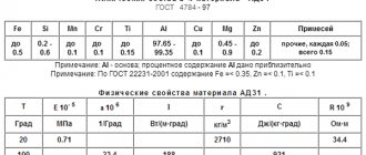
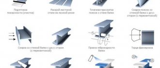
Process principle
Friction stir welding is carried out using a special tool that resembles the shape of a rod. Among the features of friction stir welding, the following points can be noted:
- The friction stir welding equipment used consists of two main parts: the shoulder and shoulder, as well as the tip.
- The tool is selected depending on the thickness of the material and its type. Some alloys are characterized by a low degree of machinability.
- The length of the tip is set depending on the thickness of the part.
- This welding method can be performed with filler material. At the time of welding, the tool rotates at high speed at the melting point. The applied pressure causes the tip to be inserted into the workpiece to the required thickness. In this case, the shoulder pad should touch the surface being treated.
- The next step is to move the tool along the seam line at a certain speed. With strong friction, the surface of the material begins to heat up greatly, due to which it begins to become plastic. The deformation occurs evenly.
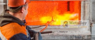
Welding process
Using a special installation, you can create a strong connection that is characterized by fairly high quality.
svarka-24.info
A new method for producing welded joints, called friction stir welding (FSW), was developed by the British Welding Institute (TWI) in 1991 [1]. Intensive study of this process, aimed at improving technology and equipment, made it possible to introduce this method abroad into the production of high-tech products in such industries as car, ship, aircraft and many others. Friction stir welding refers to processes of joining materials in the solid phase and therefore does not have the disadvantages associated with melting and evaporation of the metal. Process researchers estimate that if 10% of total welded joints in the United States were replaced by FSW, 500 million pounds/year fewer greenhouse gas emissions would be achieved. The estimated economic benefit to US industry from the introduction of STP in industrial production is $4.9 billion/year [2].
The essence of the process is as follows (Fig. 1). For welding, a rod-shaped tool is used, consisting of two main parts, namely: a shoulder or shoulder (thickened part) and a tip (protruding part). The dimensions of these structural elements are selected depending on the thickness and material of the parts being welded.
The length of the tip is set approximately equal to the thickness of the part to be welded. The diameter of the shoulder can vary from 1.2 to 25 mm. A tool rotating at high speed at the joint is brought into contact with the surface of the workpieces so that the tip penetrates into the workpieces to a depth approximately equal to their thickness, and the shoulder touches their surface. The tool then moves along the joint line at welding speed. As a result of the work of friction forces, the metal is heated to a plastic state, mixed with a rotating tool and displaced into the vacated space behind the tool moving along the joint line. The volume in which the seam is formed is limited from above by the shoulder of the tool. At the end of welding, the rotating tool is removed from the joint outside the workpiece. Due to the asymmetry of the structure of the seams in the cross section of welded joints obtained by friction stir welding, it is customary to distinguish between the advancing side, where the direction of rotation of the tool coincides with the direction of welding, and the opposite side, the retreating side.
Rice. 1. Scheme of the friction stir welding process.
FSW is used mainly for joining materials with a relatively low melting point, primarily aluminum [3] and magnesium alloys [4]. Successful welding of copper [5], nickel and titanium alloys [2], as well as steels [6] has been performed using this method. Using FSW, aluminum alloys with a thickness of up to 75 mm are welded in one pass [7]. Friction stir welding makes it possible to obtain lap joints of aluminum sheets with a thickness of 0.2 mm [8]. The welding speed of 5mm thick 6082 alloy can reach 6m/min [9]. The main parameters of the FSW process are: welding speed, tool rotation frequency, pressing and moving forces of the tool, tool inclination angle, and its dimensions. The pressing and moving forces depend on the type of material being welded, its thickness and welding speed. Welding samples from alloy 7010 - T7651 with a thickness of 6.35 mm when changing the welding speed in the range from 59 to 159 mm/min and the tool rotation speed from 180 to 660 rpm showed that with increasing rotation speed, the heat input into the metal and into the welded material increases connection, a microstructure with more uniform grains is formed [10]. At the same time, the strength and plastic properties also increase to a certain limit. As the welding speed increases, it is necessary to increase the tool rotation speed to achieve optimal conditions. However, for the complete absence of defects, as well as to ensure all the necessary properties, reliability and manufacturability, it is necessary to strictly select modes that are optimally suited for a particular product.
Most researchers point to the following advantages of friction stir welding compared to other methods for producing permanent joints [11, 12]:
– in the welding zone, the properties of the base metal are better preserved compared to fusion welding methods;
– absence of harmful fumes and ultraviolet radiation during the welding process;
– the possibility of obtaining defect-free welds on alloys that, during fusion welding, are prone to the formation of hot cracks and porosity in the seams;
– the use of filler material and shielding gas, removal of surface oxides on the edges before welding, as well as slag and spatter after welding are not required;
– there is no loss of metal alloying elements during welding.
The emission levels of Cr, Cu, Mn, Cr+6 during FSW of steels according to Rockwell Scientific (USA) are significantly lower (<0.03, <0.03, <0.02 and <0.01 mg/mm3, respectively) than during argon arc welding (0.25, 0.11, 1.88 and 0.02 mg/mm3, respectively) [2]. A comparison of production costs when using friction stir welding and consumable electrode welding (GEW) showed that the initial investment in FSW is higher, but with increasing production volumes, friction stir welding becomes more economical than arc welding [11].
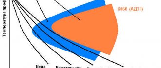
Rice. 2. Temperature distribution in the longitudinal section of the sample.
Judging by the experimental results of TWI, the maximum temperature during friction stir welding is about 70% of the melting temperature and for aluminum does not exceed 550°C. The heat input during FSW is approximately 2 times less than during argon-arc welding and for the 6N01 – T5 alloy with a thickness of 4 mm is equal to 190 and 390 J/mm, respectively (welding speed 500 mm/min) [13]. Using mathematical modeling of thermal processes during FSW, the temperature distribution in the welded plate was constructed in [14] (Fig. 2). The lower temperature of the joint zone during friction stir welding compared to consumable electrode welding explains the lower level of angular deformation in the welded joint. With FSW, the angular deformation is equal to 1/5÷1/7 of the values with SPE [12] (Fig. 3).
Rice. 3. Comparison of angular deformation between friction stir welding and consumable electrode welding (6000 series aluminum alloy, 2 mm thickness).
It is assumed that due to the low level of process temperatures, residual stresses are low. But rigid fastening imposes great restrictions on the deformation of the plates. This prevents the metal from contracting when cooling the dynamic recrystallization zone and heat-affected zone (HAZ) in the longitudinal and transverse directions, leading to transverse and longitudinal residual stresses. During FSW of alloys 2024 – T3 and 6013 – T6, it was found that the longitudinal residual stresses were higher than the transverse ones (welding speed was 300 ÷ 1000 mm/min, tool rotation speed – 1000 ÷ 2500 rpm). High tensile stresses predominate in the HAZ. The magnitude of residual stresses decreases as the welding speed and tool rotation speed decrease. The maximum values of longitudinal tensile stresses reach values of 30 ÷ 60% of the yield strength of the welded joint and 20 ÷ 50% of the yield strength of the base metal [15].
Rice. 4. Diagram of the zones of the butt joint made by FSW: A – base metal, B – heat-affected zone (HAZ), C – thermomechanical-affected zone, D – dynamic recrystallization zone (running side on the left).
The macrostructure of welded joints in friction stir welding is characterized by features that are not characteristic of welds produced by fusion welding methods. Typical for FSW is the formation of a nucleus in the center of the junction, which contains oval concentric rings that differ in structure [16]. Adjacent to the core is a complex profile that forms the upper part of the seam. The formation of oval rings is associated with the peculiarities of mixing the metal with the tip of the tool. In a welded joint during FSW, four zones are distinguished, which are schematically presented in Figure 4. Directly adjacent to zone A (base metal) is zone B, where the metal of the workpiece remains undeformed and changes its structure only under the influence of heat (heat-affected zone). Zone C, where the metal is subjected to significant plastic deformation and heating, is called the thermomechanical influence zone (TMIA). Zone D is the core of the compound where dynamic recrystallization occurs. The hardness of the metal decreases in the direction from the base metal to the center of the weld, and the minimum value is achieved in the HAZ (Fig. 5). A decrease in hardness in the HAZ occurs due to overaging, a decrease in dislocation density, or due to both of these mechanisms.
Rice. 5. Hardness distribution in the welded joint zone of alloy 7075 – T7351 [17].
Many researchers report a high level of mechanical properties of welded joints. During FSW, the welded joint of the 6082-T6 alloy has a tensile strength σв=245 MPa, while the base metal has σв=317 MPa. For 6082 –T4, aged after welding, σв=308 ÷ 310 MPa. Fatigue tests indicate a higher level of mechanical properties of joints during FSW compared to similar ones during argon arc welding [18].
The authors of [19] conducted studies of the mechanical properties of joints obtained by friction stir welding of alloy 5083 at cryogenic temperatures, which was intended to prepare the production of containers for liquefied hydrogen. Specimens with a thickness of 30 mm were welded at a speed of 40 mm/min. Studies at 77K in liquid nitrogen, 20K in liquid hydrogen and 4K in liquid helium have shown that the level of properties of joints with FSW is higher than with argon arc welding.
Rice. 6. Mechanical properties of a welded joint made by various welding methods.
The authors of [20] dealt with the problems of FSW of cast aluminum alloys. In industrial production, cast alloys often have to be welded to those produced by extrusion. Alloys ADC1 and A6061 – T6 with a thickness of 4 mm were used. The results obtained with FSW were compared with those obtained with argon arc and laser welding. As can be seen from Figure 6, FSW provides better joint properties. The tensile strength is 80% of the strength of A6061 - T6. In bending testing, fracture in friction stir welding occurs along the base metal. Positive results of friction stir welding of dissimilar alloys, as well as aluminum alloys with steels, are reported in publication [21]. In FSW of SS400 steel and A5083 alloy with a thickness of 2 mm, the tensile strength was 240 MPa, which is 86% of the strength of the aluminum alloy.
Rice. 7. Friction stir spot welding machine (left), cross section (top right) and appearance of samples (bottom right).
As a disadvantage of the FSW method, the authors [2, 12] note the formation at the end of the weld of a hole equal to the diameter of the tip, which requires moving the seam beyond the working section of the workpiece or filling the hole after welding using other methods, such as friction welding of special plugs.
The ongoing improvement of technology and equipment makes it possible to overcome existing shortcomings, as well as expand the scope of application of the method. Although friction stir welding is used mainly for butt and lap welds, it is also possible to produce fillet, T, and spot welds. Friction stir spot welding can be implemented in two ways. The first method is immersion spot welding (PFSW), which was patented by Mazda (Japan) in 2003. In this case, a rotating tool is plunged into the part, bringing it to a plastic state and mixing the metal under the shoulder. After this, the tool rises, leaving a characteristic depression in the part. The second method is friction spot welding with seam filling (RFSW), which was patented by GKSS-GmbH in 2002 [2]. For this method, a tool is used whose tip and shoulder have separate drive systems. The rotating tool is lowered into the part, while the tip squeezes out and mixes the metal underneath it, and then it is removed, and the metal under the shoulder fills the recess, and thus a seam without a hole is obtained (Fig. 7).
Rice. 8. Appearance of a tool made of polycrystalline cubic boron nitride [2].
Welding tools are usually made of tool steels H13 (AISI), SKD61, SKD 11, SKH 57 (JIS), stainless martensitic steel SUS440C (JIS). In this case, it is possible to use composite instruments in which the tip is made of cobalt alloy MP159, and the shoulder is made of N13 [22]. For FSW welding of steels up to 0.5″ thick, MegaStir has developed a tool made from polycrystalline cubic boron nitride. Its resistance to fracture is higher and allows you to give the tip the shape necessary for favorable flow of metal in the welding zone (Fig. 8). The tool is positioned at a slight angle of 2 ÷ 3° in relation to the surface of the part [16, 23]. With this arrangement of the tool at a slight angle to the surface of the part, the highest quality indicators are achieved.
Rice. 9. Design of the Bobbin Tool.
The tool, which also serves as a backing for the workpieces to be joined, is shown in Figure 9 [24]. NASA is developing a self-adjusting tool, the length of the tip of which is determined by the forces acting on it. When the load on the tip deviates from the specified value, its length is automatically adjusted. This allows you to weld workpieces of variable cross-section and avoid the formation of holes when making circumferential welds.
Rice. 10. Design options for the WhorlTM working tool.
For welding aluminum alloys of significant thickness, the WhorlTM (Fig. 10) and TrifluteTM [25] families of tools have been developed, which allow welding of aluminum alloys with a thickness of 50 mm in one pass. New options for FSW are Re-StirTM, Skew-StirTM, Com-StirTM technologies [26]. Re-StirTM technology with variable rotation of the tool clockwise and counterclockwise eliminates the seam asymmetry inherent in traditional FSW. Using the Skew–StirTM technology, the tool is slightly inclined in relation to the machine spindle so that the point of intersection of the spindle and tool axes, called the focal point, can be located above, below or in the workpiece being welded, depending on the properties of the material and the mode parameters. This allows you to obtain a wider seam when rotating the tool during the welding process. A – SkewTM and Flare – TrifluteTM tools provide stronger lap joints. Com-StirTM technology consists of combining rotational and orbital movements of the tool during the welding process. As a result, wider seams are obtained and are mainly used to join dissimilar materials. A system with two parallel Twin – StirTM tools has been developed [27].
Rice. 11. Connections made on a Mazda RX – 8 using friction stir spot welding [2].
The development of new friction stir welding technologies continues. At the University of Missouri - Columbia (USA), they are developing FSW with accompanying additional heating when passing current through the tip of the tool. The Center for Processing and Joining of Advanced Materials (USA) is developing FSW with induction preheating of the material, which will increase the welding speed, reduce the forces acting on the tool, and reduce its wear [2]. In [28], the possibility of using a laser for preheating metal during FSW of magnesium alloys is studied.
Rice. 12. Equipment for friction stir welding in a vertical position.
Due to the small number of factors influencing the FSW process and the fairly simple design of the equipment, the method is ideal for automation and robotization [29]. The Tricept805 allows welding of aluminum up to 10 mm thick.
Friction stir welding is already used by many manufacturers of various high-tech products. The companies GDLS (GeneralDynamicsLandSystems) and EWI (EdisonWeldingInstitute) carried out joint work, the purpose of which was to provide the required ballistic characteristics of the connections of armor plates made of aluminum alloy 2195 - T87 for naval armored transporters. Welding using the FSW method instead of argon-arc plates with a thickness of 31.8 mm made it possible to obtain acceptable strength properties of the joints and more ductile (2-3 times) seams. As a result, the welded joints (including fillet joints) successfully passed ballistic tests [22].
Rice. 13. Friction stir welding facility for a Delta rocket fuel tank at Boeing.
To prevent deterioration of the properties of the superconducting Nb – Ti wire, it must be connected to a rigid element made of pure Al at a temperature below 400°C. Previously, low-temperature soldering was used for this, but the soldered seams had low strength. FSW provided the required properties of the welded joint in liquid helium [12].
For three years since 2003, FordMotorCo. (USA) manufactured several thousand Ford GT vehicles using FSW to weld the central compartment, which houses and isolates the fuel tank from the internal compartment and provides spatial rigidity to the frame [2]. FSW improves dimensional accuracy and increases strength by 30% compared to similar units using gas-shielded arc welding. Another work [30] describes the process of manufacturing a MazdaRX-8 car body using friction spot welding (Fig. 11). Since 2003, over 100 thousand cars have been produced whose doors are made by friction spot welding [7]. Based on the successful application of this welding method, the company plans to perform similar connections on the new generation of MX-5 vehicles.
Rice. 14. Eclipse 500 aircraft with friction stir welding components.
They are actively studying the FSW process in the aerospace field (Fig. 12) [24]. In 2001, the process was introduced into the production of the external tank of the launch vehicle for re-entry spacecraft. The technology involves welding 8 longitudinal seams on a 2195 alloy tank for liquid hydrogen and 4 longitudinal seams on a tank for liquid oxygen. That's about ½ mile of seams on each tank. Equipment is being developed for repair friction stir welding in space vacuum conditions. The concept is based on the fact that the high tool rotation speed (30,000 rpm) during FSW will reduce the force required to perform welding.
began using friction stir welding in the production of the Delta II and III rockets (Fig. 13) [31]. Welding is performed on an 8.4 m long fuel tank, a 12 m long liquid oxygen tank and other structures. Friction stir welding provides improved quality (one defect per 76.2 m weld) compared to argon arc welding (one defect per 8.4 m weld). FSW reduces the manufacturing time of a welded structure. Production of Delta II rockets increased from 8 to 17 units per year.
Work on FSW of finned panels for aircraft wings made of alloys 2024, 7475, 7050 with a thickness of 4 mm is reported in article [32]. High quality connections are ensured when using STP on the Airbus A350 aircraft and two new versions of the A340 (A340 - 500 and A340 - 600) [2]. EclipseAviation is completing certification of the Eclipse 500 business jet with FSW components (Fig. 14).
Rice. 15. External view of the experimental setup for FSW of thin-sheet (1.8 ÷ 2.5 mm) aluminum alloys.
The above analysis of published information indicates that friction stir welding is successfully developing and is being used in various branches of industrial production. Most publications concern welding of aluminum alloys of medium and relatively large thickness. It should be borne in mind that difficulties usually arise when connecting workpieces with a thickness of 0.5 - 3 mm, as well as more than 40 mm. In connection with this, as well as with the complications that arise when ensuring the accuracy of the assembly of thin-walled workpieces for welding at the Electric Welding Institute named after. E. O. Paton conducted research on the FSW process on a special experimental setup (Fig. 15). The work was performed on aluminum alloys AMg6, 1201, 1460 with a thickness of 1.8 ... 2.5 mm. In Fig. Figure 16 shows the appearance of a welded joint of the AMg6 alloy produced by the FSW method. At the same time, the effectiveness of welding tools with different working part profiles was tested.
Rice. 16. Appearance of a weld obtained by friction stir welding (AMg6 aluminum alloy 2 mm thick).
It has been established that joints using this welding method have a high level of mechanical properties (the strength coefficient of welded joints is 0.7 ÷ 0.9 from the strength level of the base metal (table)) and the relevance of work to improve the method of friction stir welding of structures using thin sheet materials.
Table
Mechanical properties of aluminum alloy joints produced by friction stir welding
| Aluminium alloy | Strength of the welded joint σww, MPa | Bend angle of welded joint α, deg |
| AMg6 | 343 | 180 |
| 1420 | 362 | 96 |
| 1201 | 294 | 180 |
| 1460 | 325 | 180 |
Literature
- US Pat. No. 5460317. Friction stir butt welding/ WM Thomas, ED Nicholas, JC Needham et al.; Publ. 1995.
- Arbegast WJ Friction stir welding. After a decade of development // Welding J. – 2006. – 85, No. 3. – P. 28 – 35.
- Ito T., Motohashi Y., Goloborodko A. et al. Microstructures and room temperature mechanical properties in friction-stir-welded joints of 7075 aluminum alloys // Journal of the Japan Welding Society. – 2005. – 74, No. 3. – P. 9 – 13.
- Aritoshi M. Friction stir welding of magnesium alloys sheets // Journal of the Japan Welding Society. – 2005. – 74, No. 3. – P. 18 – 23.
- Nakata K. Friction stir welding of copper and copper alloys // Journal of the Japan Welding Society. – 2005. – 74, No. 3. – P. 14 – 17.
- Klingensmith S., Dupont JN, Marder AR Microstructural characterization of a double-sided friction stir weld on a superaustenitic stainless steel // Welding J. - 2005. - May. – P. 77 – 85.
- Martin J. Pushing the boundaries – friction stir goes deeper than before // TWI Connect. – 2006. – January/February. – P. 1.
- Teh NJ Small joints make a big difference // TWI Connect. – 2006. – 143, No. 4. – R. 1.
- Eriksson L.G., Larsson R. Rotational friction welding - scientific research and new areas of application // Mechanical Engineering Technology. – 2003. – No. 6. – R. 81 – 84.
- Hassan AA, Prangnell PB, Norman AF et al. Effect of welding parameters on nugget zone microstructure and properties in high strength aluminum alloy friction stir welds// Sci. Technol. Weld. Joining. – 2003. – 8, No. 4. – R. 257 – 268.
- Defalco J. Friction stir welding vs. fusion welding // Welding J. – 2006. – 85, No. 3. – P. 42 – 44.
- Okamura H., Aota K., Ezumi M. Friction stir welding of aluminum alloy and application to structure // J. of Jap. Institute of Light Metals. – 2000. – 50, No. 4. – P. 166 – 172.
- Aota K., Okamura H., Masakuni E. et al. Heat inputs and mechanical properties friction stir welding // Proc. of the 3rd International Friction Stir Welding Symposium, Kobe, Japan, 27 – 28 September, 2001.
- Lambrakos SG, Fonda RW, Milewski JO et al. Analysis of friction stir welds using thermocouple measurements// Sci. Technol. Weld. Joining. – 2003. – 8, No. 5. – R. 385 – 390.
- Dalle Donne C., Lima E., Wegener J. et al. Investigation on residual stresses in friction stir welds // Proc. of the 3rd International Friction Stir Welding Symposium, Kobe, Japan, 27 – 28 September, 2001.
- Volpone M., Mueller SM Friction stir welding (FSW): le ragioni di un successo // Rivista Italiana della Saldatura. – 2005. – No. 1. – R. 23 – 30.
- Chao YP, Wang Y., Miller KW Effect of friction stir welding on dynamical properties of AA 2024-T3 and AA 7075-T7351 // Welding J. – 2001. – No. 8. – R. 196 – 200.
- Ericsson M., Sandstorm R. Influence of welding speed on the fatigue of friction stir welds, and comparison with MIG and TIG // International Journal of Fatigue. – 2003. – No. 25. – P. 1379 – 1387.
- Hayashi M., Oyama K., Eguchi H. et al. Mechanical properties of friction stir welded 5083 aluminum alloy at cryogenic temperatures // Proc. of the 3rd International Friction Stir Welding Symposium, Kobe, Japan, 27 – 28 September, 2001.
- Nagano Y., Jogan S., Hashimoto T. Mechanical properties of aluminum die casting joined by FSW // Proc. of the 3rd International Friction Stir Welding Symposium, Kobe, Japan, 27 – 28 September, 2001.
- Kimapong K., Watanabe T. Friction stir welding of aluminum alloy to steel // Welding J. – 2004. – October. – P. 277 – 282.
- Colligan KJ, Konkol PJ, Fisher JJ et al. Friction stir welding demonstrated for combat vehicle construction// Welding J. – 2003. – March. – P. 34 – 40.
- Shibayanagi T., Maeda M. Characteristics of microstructure and hardness in friction stir welded 7075 aluminum alloy joints // Trans. JWRI. – 2004. – 33, No. 1. – P. 17 – 23.
- Ding J., Carter R., Lawless K. et al. Friction stir welding flies high at NASA// Welding J. – 2006. – March. – P. 54 – 59.
- Dolby RE, Johnson KJ, Thomas WM The joining of aluminum extrusions // La metallurgia italiana. – 2004. – No. 3. – P. 25 – 30.
- Pekkari B. The future of welding and joining // Svetsaren. – 2004. – No. 1. – R. 53 – 59.
- Thomas W., Staines D. Better joints using two contra – rotating FSW tools// TWI Connect. – 2006. – May/June. – P. 7.
- Kohn G., Greenberg Y., Makover I. et al. Laser – assisted friction stirring// Welding J. – 2002. – February. – P. 46 – 48.
- Cook GE, Smartt HB, Mitchell JE et al. Controlling robotic friction stir welding//Welding J. – 2003. – June. – P. 28 – 34.
- Kato K., Sakano R. Development of spot friction welding and application for automobile body // J. of Light Metal Welding & Construction. – 2004. – 42, No. 11. – P. 8 – 13.
- Imuta M., Kamimuki K. Development and Application of Friction Stir Welding for Aerospace Industry // Proc. of the IIW International Conference on Technical Trends and Future Prospectives of Welding Technology for Transportation, Land, Sea, Air and Space, Osaka, Japan, 15 – 16 July, 2004. – P. 53 – 64.
- Kumagai M. Application of FSW for aircraft // Welding Technology. – 2003. – 51, No. 5. – P. 74 – 78.
The main parameters that affect the properties of the seam
It is worth considering that some parameters influence the basic qualities of the resulting seam. The main ones include:
- The speed of movement of the tool determines the friction force that occurs between the cutting surface and the workpiece. Temperature also depends on this.
- The rotational speed of the tool also affects the temperature in the processing zone.
- The angle of inclination of the tool also affects the characteristics of friction stir welding.
- The geometric dimensions of the device used are selected depending on the type of connection needed.
- Pressing and moving force can also be considered the most important parameters.
Weld
When considering the friction welding method, we note that such technology is actively developing today. This is due to the fact that the natural heating process does not lead to the appearance of internal deformations and other defects.
Preparation
When designing workpieces for subsequent welding, it is important to consider a number of factors:
- welding equipment capabilities;
- degree of weldability of materials;
- securing workpieces in a welding machine;
- the cost of preparatory measures for welding workpieces and subsequent processing of welds;
- compliance with the required degree of alignment and angular placement of workpieces;
- formation of a uniform temperature regime and identical deformation conditions;
- correct choice of allowances for the length and diameter of the workpieces.
Ensuring the required alignment depends on the degree of reliability of fastening the parts in the clamping devices of the unit. In this context, the level of rigidity of the welded elements along the length of their exit from the clamps becomes a relevant parameter. If the length of the outlet is less than the required size, this leads to temperature release of the clamping devices.
With friction welding, the condition of the surfaces being joined has the least effect on the quality of the welded joints than with other pressure welding methods. Joining surfaces can be obtained by cutting with a guillotine or a circular saw. Irregularities can be eliminated by lapping or increasing the heating time.
Main Applications
Today, the technology in question is used in most cases in the production of vehicles. This is due to the following points:
- When using a technology that involves melting metal, perforation of thin sheets of steel may occur. An example is the processing of aluminum.
- The FSW technology under consideration determines the release of less heat. That is why the likelihood of such defects occurring is negligible.
- Friction stir welding is characterized by high efficiency, since its use leads to a halving of energy consumption.
- The use of technology makes it possible to reduce the weight of the resulting structure.
All the above points determine that the technology in question has become widespread as follows:
- Shipbuilding.
- Aerospace industry.
- Electrical industry.
- Construction.
- Food industry.
- Railway transport.
Friction Stir Welding Equipment
Friction stir welding is most often used to join copper alloys. An example is the production of containers that can be used to store nuclear waste and critical parts.
Friction stir welding
This method was developed and introduced in 1991.
Initially, this method was developed for aluminum and aluminum alloys, since during fusion welding most of the material was spent on the design of the weld, and the plastic properties of aluminum were also lost during fusion.
After implementation of the method and good results, it was found that the rotation stir welding method is suitable for a wide range of metals.
Main areas of application:
- shipbuilding, especially the submarine fleet, where completely sealed welded joints are required;
- construction of space objects and shuttles;
- storage facilities and tanks for storing cryogenic gases and liquids that have increased volatility.
The most unique products that are produced with elements of rotational welding are copper containers intended for storing waste from the nuclear industry.
Advantages
The method under consideration is characterized by quite a large number of advantages. By mixing the workpieces with friction you can get a high-quality seam. The quality of friction stir welding is improved by using different tools. The advantages include the following:
- The blanks do not need to be carefully prepared. If we consider contact and other technologies, then before direct processing the surface must be thoroughly cleaned of various contaminants and be smooth. Otherwise, the quality of the seam will be poor and it will not be possible to achieve the required tightness. In this case, it is enough to clean the surface from large and strongly visible contaminants.
- There is no need for special edge preparation. Some technologies involve removing the surface layer of metal and carrying out certain technological operations that will significantly increase the strength of the connection.
- It is possible to connect metal that cannot be processed in the usual way. An example is materials that cannot be welded using conventional welding methods. In this case, there is practically no need for preheating the processing zone.
- The strength of the resulting connection is quite high. That is why the technology can be used to produce critical products with various fields of application.
- There is no need to use filler wire. This point significantly reduces the cost of the work performed.
- At the junction the grain is fine. Due to this, the density of the weld seam and its resistance to various types of influence increases.
- The absence of pores also has a beneficial effect on the quality of the resulting compound. This property can be associated with the fact that during strong heating, various gases and substances are released, which cause the formation of porosity.
- The almost complete absence of signs of warping and thermal deformation means that finishing is required extremely rarely.
- After welding work using friction stir welding, the product is almost immediately ready for use. In this case, there is no need to carry out any preparatory actions.
- The degree of surface reaction to environmental influences does not increase. In other words, the material does not corrode.
- During the procedure, no toxic gases or other emissions are generated at the time of friction stir welding. In addition, more common methods based on the influence of current lead to the formation of an electric arc, which has a negative impact on the operator and others in the absence of special personal protective equipment.
- The production cycle time is reduced by approximately 50% compared to other common methods.
- Savings on the amount of energy consumed are 20%.
As previously noted, the production of defect-free welds on alloys has determined the widespread use of friction stir welding. An example is the receipt of body parts.
Efficiency of the method
At first, friction welding is quite difficult, but gradually, as the aluminum and the nozzle acquire a suitable operating temperature, the process begins to go much easier. And if at first the nozzle moves sideways, then it will move smoothly, forming an even and beautiful seam. Upon completion of the work, it is clear that the metal has been welded externally, although on the inside the seam is not of sufficient quality.
When broken, the welded joint is very strong, but in the opposite direction it is very easy to tear it with your hands. The metal is not cooked deeply and therefore the inner layer does not melt or mix properly.
So we can conclude that welding aluminum with a drill is quite possible, but the result leaves much to be desired. Therefore, if you need to create a durable and high-quality result, it is better to use the classic method, which will definitely ensure a reliable seam and a strong structure at the end.
Flaws
The procedure also has several disadvantages that need to be taken into account. An example is the possibility of breaking the continuity of a seam. In addition, some alloys are less susceptible to friction.
The improvement of the method under consideration has determined that defects form on the surface of the seam in the most extreme cases. Most often this happens when technology is violated and low-quality tools are used.
The technological capabilities of the procedure in question are quite extensive. Let's take the following points as an example:
- Process automation.
- Obtaining quality products at insignificant financial costs.
- Obtaining a seam without a strong influx of metal.
Welding copper and steel
As previously noted, friction stir welding is actively developing today. This is why equipment with higher performance may appear in the future.
Features of the formation of joints when using FSW
As previously noted, friction stir welding is characterized by a fairly large number of features. Some of the key points regarding connection formation include the following information:
- The metal is heated gradually to a temperature that does not lead to a change in its basic properties.
- The temperature rises in only one local place. This ensures high quality of the resulting connection.
- If the recommendations for carrying out the procedure in question are followed, defects occur extremely rarely. That is why in most cases it is enough to carry out a visual inspection of the connection point for quality control.
Modern equipment makes it possible to obtain a minimal seam, which after finishing is almost invisible. The widespread use of the method under consideration can also be associated with the fact that it is suitable for working with difficult-to-cut metals.
Friction stir welding is an actively developing technology, which today is increasingly being introduced into various industries.