Drilling machines can be classified as equipment with universal capabilities. At the same time with the ability to drill holes of various diameters, cleanliness and accuracy, with their help it is possible to perform numerous operations in accordance with the technological process of surface treatment. The use of this category of equipment is optimal if the technology provides for the following actions:
- drill, bore holes of various diameters;
- countersink the drilled holes to the appropriate parameters, countersink the necessary recesses to accommodate the protrusions of the fasteners;
- expand the surface of the holes within specified limits;
- roll out holes using ball and roller mandrels to a given level of roughness;
- perform internal thread cutting;
- trim (chase) the ends of parts in order to align them.
There are also other possibilities for using equipment in this category.
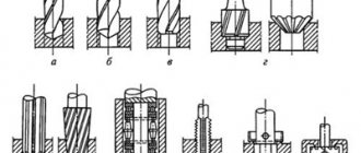
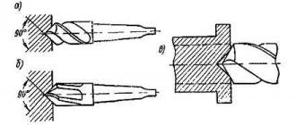
Rice. 1. Work performed on drilling machines
a – drilling; b – drilling; c – countersinking; g – countersinking; d – deployment; e – rolling; g – cutting internal threads; h – cutting (countering) the ends
Metal processing by drilling: basic information
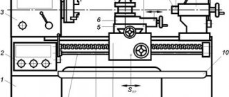
Drilling processing is carried out on special drilling machines, where the workpiece is rigidly fixed, and the cutting tool rotates and at the same time moves translationally along the axis of the hole drilled in the workpiece (this movement is called feed).
There are vertical drilling and radial drilling machines. The former are used for drilling holes in small workpieces, which, during the setting process, are moved along the table so that the axis of the drill and the axis of the future hole coincide. To work with heavy and large workpieces, radial drilling machines are used. On them, the workpiece is immediately rigidly fixed on the table, and the machine spindle is installed in the desired position. Work performed on drilling machines:
- drilling;
- deployment;
- countersinking;
- thread cutting.
Cutting tools used for processing parts on drilling machines:
- drill;
- sweeps;
- countersinks;
- taps (for cutting threads).
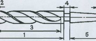
The main cutting tool when drilling parts is a drill. Typically, twist drills are used for this purpose, consisting of a working part, a neck and a shank. The working part, in turn, consists of two parts - cutting and centering. The cutting part has two cutting working edges connected to each other by a bridge. The centering part has a pair of screw strips that act as guides during the process of drilling metal, as well as two spiral grooves through which cutting fluid is supplied and chips are discharged. The shank can have a conical or cylindrical shape. The first option is intended for fastening the drill in the spindle using adapter sleeves, the second option is for fastening it in the chuck. The drill neck carries a masking, where, among other parameters, the diameter of the drill and the material of its cutting edge are indicated.
Machining holes on drilling machines
Making holes with a drill is the most common method due to the use of cheap tools, relatively cheap machines, and high productivity.
When drilling holes with a diameter greater than 35 mm in solid material, it is recommended to use two drills to reduce the axial force and prevent the drill from moving away from the intended direction.
When making a hole with a diameter greater than 30 mm according to the 3rd accuracy class, in addition to the drill, a countersink and a reamer are used; for diameters less than 30 mm after the drill - only a reamer.
When making holes with a diameter of 15 to 20 mm according to the 2nd accuracy class, a countersink and a reamer are used after the drill; for diameters greater than 20-25 mm, one or two reamers are used after the drill and countersink.
In fig. 147 shows diagrams for processing holes on a vertical drilling machine, indicating the dimensions that determine the allowance for each tool.
Fig. 147. The order of operations when processing holes on a vertical drilling machine.
Fig. 148. Drilling, boring, trimming and reaming holes through a jig.
Each tool must be guided by the jig sleeve, otherwise the direction and accuracy may be incorrect (Fig. 148).
When processing holes cast or stitched in a forge, the drill is replaced with a countersink (Fig. 149); subsequent processing remains unchanged.
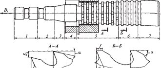
To quickly change cutting tools on vertical drilling machines, special quick-change chucks are used (Fig. 150).
Fig. 149. Processing a cast hole with a countersink.
Fig. 150. Drilling and trimming with quick-change chuck.
Fig. 151. Machining a cast hole with a countersink with a rear direction.
Fig. 152. Machining a cast hole with a countersink with a rear direction without a intake cone.
For cast holes with a diameter greater than 25-30 mm, it is very good to use countersinks with a rear direction (Fig. 151), and for holes that are very far from the axis, countersinks with a rear direction, but without a intake cone (Fig. 152), which is the purpose protect the countersink from being pulled away.
Instead of countersinks, you can use double-sided cutters in mandrels, also with a rear direction (Fig. 153); they are cheaper to manufacture, but less productive than countersinks. A mandrel with cutters (Fig. 154) is used for large diameters in small- and medium-scale production on vertical, but more often on horizontal boring machines.
Fig. 154. Mandrels with cutters for processing holes.
Fig. 155. Countersinking with single and double-sided round cutters.
Countersinking can be done with single- and double-sided round cutters
in the mandrel (Fig. 155). For countersinking internal bosses, both special removable countersinks (Fig. 156) and round single- and double-sided cutters (Fig. 157) are used.
Fig. 156. Countersinking of the internal boss with a removable countersink.
Fig. 157. Countersinking of the internal boss with a round one-sided cutter.
Fig. 153. Machining a cast hole with a double-sided cutter with a rear direction.
Fig. 158. Mandrel with mounted countersinks for processing several holes.
When processing several holes located on the same axis, mandrels with mounted countersinks are used (Fig. 158).
Currently, they are beginning to use countersinks with inserted knives secured using wedges with a corrugated surface (Fig. 159).
Knives can be rearranged during sharpening. Special boring machines use Kelle or Davis type blocks with two cutters, which are sharpened in special mandrels and can be quickly changed on the machine (Fig. 160).
Fig. 160. Special mandrel for boring machines.
Fig. 159. Countersink with insert knives.
Fig. 161. Special knife for processing shaped surfaces.
Fig. 162. Shaped countersink for processing holes.
Fig. 163. Combined countersink for processing holes.
Fig. 164. Mounted countersink with hard alloy plates.
Currently, plates made of hard alloys are used for drills, countersinks and reamers, which are soldered to the tool. Figure 164 shows a mounted countersink with carbide plates.
Reamers are divided into manual and machine and are made solid and sliding.
Hand reamers have long teeth and a long, conical sharpened part called the fence. Figure 165 shows an adjustable adjustable reamer. Its cylindrical tail has a square end, onto which a handle is placed to rotate the reamer. Single-tooth reamers (Fig. 166) are used mainly for subsequent alignment of long holes reamed on the machine; the hardened part of such reamers serves as a guide.
Fig. 165. Adjustable manual reamer with conical screw.
Fig. 166. Single-tooth reamer for processing holes.
Solid machine reamers are used for diameters up to 32 mm. Attachment reamers for diameters greater than 30 mm are used to save material. Sliding reamers are used for diameters from 25 to 100 mm (Fig. 167).
Gisholt-type reamers with insert knives are widely used, used for diameters from 35 to 150 mm (Fig. 168):
they are adjusted by placing thin paper or metal spacers under the knives.
When working with finishing reamers on lathes and turret machines, swinging mandrels are used (Fig. 169), which compensate for the mismatch between the hole axis and the direction of the reamer.
Fig. 167. Sliding scan.
Fig. 168. Reamer with insert knives.
Fig. 169. Swinging mandrel.
Self-centering reamers (Fig. 170), sometimes called floating, are plates loosely inserted into a holder, designed to remove a very thin layer of chips.
Due to the fact that these reamers are guided by the hole itself, they cannot straighten the curvature and position of the axis, but they give a clean surface and an accurate diameter.
Fig. 170. Self-centering reamer for machining holes.
The use of only two cutting edges makes sharpening of such reamers easier.
The wear of the plates is compensated by adjusting the sliding plates, which are set to a micrometer.
Such reamers can be used for hole diameters from 25 to 500 mm.
For conical holes up to 140 mm in diameter, a set of two or three reamers is usually used due to the need to remove a large amount of metal.
A hole is drilled using a drill whose diameter is 1-2 mm less than the diameter of the incoming end of the rough reamer; the depth of this hole is 2-6 mm greater than the length of the cone.
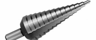
For diameters greater than 25 mm, it is recommended to drill the hole with several drills of different diameters to form a stepped hole approaching the shape of the rough reamer.
After the drill, two or three reamers are used alternately (Fig. 171).
Holes for conical pins with a diameter of less than 5 mm are reamed using a pentagonal reamer with straight grooves (Fig. 172).
When drilling a hole for a thread, the diameter of the drill is taken to be greater than the internal diameter by 0.30-0.40 of the thread depth (Fig. 173).
For viscous materials, drill diameters are larger than for hard materials.
Vertical drilling, radial drilling and horizontal boring machines are used to process holes.
Fig. 171. Order of operations for processing conical holes.
Fig. 172. Pentagonal reamer with straight grooves.
Fig. 173. Determination of the diameter of a drill for threading.
Drilling methods
Depending on the type of production and the task at hand, metal processing by drilling can be performed in different ways.
Drilling along the jig and along the markings
In small-scale and single-piece production, holes are drilled in parts according to markings. The workpieces arrive to the driller already marked (with the center of the future hole and control circles marked on them). First of all, preliminary drilling is carried out. It is carried out with manual feed, the diameter of the test hole is approximately 0.25D. Next, the spindle with the drill is retracted, the chips are removed and it is checked whether the resulting test circle coincides with the marked control circle. If there is an exact match, metal drilling continues and is completed. If there is a deviation, an adjustment is necessary: in the direction where it is necessary to move the drill, a narrow chisel is used to cut grooves along which it should go to the desired point. After this, drilling continues until the desired result is achieved.
In conditions of mass production, in order to reduce the time for setting up the machine and make the processing of parts on drilling machines more accurate, jigs are used. They are designed to fix the workpiece in the desired position and precisely guide the cutting tool in accordance with the requirements of the technological process. The workpiece is placed in the mounting base, and the direction of the drill is provided by jig bushings. The worker is not involved in setting up the machine and/or checking the accuracy of the settings, but only installs the workpiece, turns the machine on and off, after which he removes the processed workpiece and installs the next one. This reduces the time spent on drilling holes in parts and increases processing accuracy. Conductors are not used in individual production due to the fact that it is unprofitable to make a special device for drilling holes in several parts.
Through and blind holes
Holes that pass through the entire part are called through, and those drilled to a certain depth are called blind. Their drilling processes have significant differences. So, for example, at the moment the drill leaves the workpiece from the opposite side, the drill may jam, or it may break due to a sharp decrease in the resistance of the workpiece material. Considering that operations on a drilling machine are usually performed with mechanical feed, it is necessary to switch to manual feed and reduce the feed speed to the lowest possible.
There are three ways to drill blind holes:
- On machines with a device for automatically turning off the spindle feed, when setting up for the manufacture of a part, the required drilling depth is set.
- On machines without an automatic feed shut-off device, a special chuck with an adjustable stop is used, installing the stop sleeve relative to the body at the required drilling depth (accuracy up to 0.5 mm).
- If greater accuracy in depth is not needed, it is marked with chalk directly on the drill.