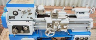
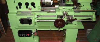
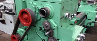
The screw-cutting lathe 16K20 belongs to the category of universal metal-cutting equipment, suitable for performing a number of operations. The machine was produced in the period from the early 70s to the mid-80s by Moscow. Currently, only used units are on the market, but due to its reliability, low price and ease of maintenance, it is still widely used today for training purposes, in repair shops, as well as in production and repair shops for single and small-scale production of parts.
Capabilities of the 16K20 machine
The design characteristics of the 16K20 lathe allow it to be effectively used for turning surfaces with a workpiece length of up to 2000 mm and a weight of up to 1300 kg of both cylindrical and conical shapes. It can also be used for cutting workpieces, preparing holes, preparing various types of threaded connections - metric, inch, modular and pitch.
The machine's capabilities allow you to produce threads with different pitches. Thus, it is possible to cut modular and pitch threads with a pitch of 0.5 to 56, inch threads with a pitch of 0.5 to 112 threads per inch, and metric threads with a pitch of 0.5 - 112 mm. The screw-cutting lathe has an accuracy class H, ensures a deviation from cylindricity of no more than 7 microns, conicity - no more than 20 microns per 300 mm, end surface - 16 microns per diameter of 300 mm.
Technical capabilities and characteristics of 16K20
Screw-cutting lathes 16K20 (as well as their analogues) are distinguished by the following characteristics.
- The spindle can rotate in the frequency range of 12.5–1600 rpm.
- It is allowed to process parts whose maximum cross-section is 310 mm above the recess, 400 mm above the bed and 220 mm above the support.
- Rapid movements in the transverse direction can be made at a speed of 1.9 m/min, longitudinal movements - 3.8 m/min.
- The technical capabilities of the 16K20 screw-cutting lathe allow it to produce threads with various parameters. Their pitch can be in the range: 0.5–56 (modular and pitch), 0.5–112 threads per inch (inch), 0.5–112 mm for metric.
- The length of the workpiece can be up to 2000 mm.
- The number of longitudinal and transverse feeds is 22 and 24, respectively. The range of longitudinal feeds is 0.05–2.8 mm/rev, transverse feeds are 0.025–1.4 mm/rev.
- The characteristics of the 16K20 machine allow processing workpieces weighing up to 1300 kg.
- To rotate the spindle, you can select one of 22 speeds (direct).
- The hole in the spindle has a diameter of 52 mm.
The kinematic diagram of the machine can be found in the photo below:
Kinematic diagram of the 16K20 machine (click to enlarge)
Depending on the length indicated in the equipment passport, the weight of the 16K20 machine can be:
- 3685 kg (for model with a length of 3795 mm);
- 3225 kg (3195 mm);
- 3005 kg (2795 mm);
- 2835 kg (2505 mm).
The engine power of the hydraulic station and the main drive of the 16K20 machine (according to the passport and actual) is 11 kW. Accordingly, this indicator is taken as the power of this model.
Controls of the machine 16K20
To start the 16K20 screw-cutting lathe, the operator needs to press a button, which closes the electrical circuit in the contactor coil. In addition to the main button, the machine has a number of elements through which the following equipment options are controlled:
- moving the equipment support and carriage at high speeds (this option is controlled using the so-called jog button);
- stopping the rotation of the equipment motor;
- starting and stopping the coolant pump.
Read also: How to calculate the gear modulus
The electrical circuit of the 16K20 screw-cutting lathe also contains a special relay, which serves to limit the idle speed of the engine. The diagram itself can be found below:
Circuit diagram of a 16K20 lathe (click to enlarge)
The handles located on the machine body are used to solve such problems as:
- selection of the type of work to be performed: type of thread to be cut and feed characteristics;
- quill fixation;
- friction clutch control;
- movement of the carriage and longitudinal movement of the slide;
- setting the thread pitch and feed value for its execution;
- disabling the feed box - for those cases when the thread is cut directly;
- selection of spindle rotation mode – number of revolutions;
- turning the lead screw nut on and off;
- start button of the input circuit breaker;
- choice of thread cutting direction;
- selecting a mode for cutting threads with normal or increased pitch.
On 16K20 machines, a steady rest can be used, which is designed to prevent the workpiece from bending during work, and also helps to fix it, thereby increasing the accuracy of processing. The lunette looks like this:
Steady rest for screw-cutting lathe 16K20
Design features of the machine 16K20
Let us note the main features and advantages of the machine, thanks to which it is still one of the most reliable and popular solutions for equipping repair and production workshops:
- The box-shaped frame is placed on a massive, monolithic base, which ensures the rigidity of the entire structure.
- High precision movement of the caliper and movable tailstock thanks to reliable guides.
- Possibility of fixing the workpiece in the chuck or by clamping in the centers.
- Reliable fixation of the cutter thanks to the design of the holder.
- High-precision spindle bearings guarantee high-precision positioning and rotation and do not require adjustment during operation.
- High security thanks to a range of fencing and locking elements. Emergency caliper shutdown.
- The headstock mechanism allows for four rows of spindle rotation numbers.
- The output shaft of the headstock is rigidly connected to the feed box through the engagement of replaceable gears. This ensures precise movement of the caliper from the lead shaft or lead screw depending on the operation.
- High precision of operations due to the presence of a ruler with sights for effectively checking the longitudinal and transverse movement of the cutting tool.
You can study the main technical characteristics of the 16K20 machine in the table below:
| Technical characteristics of the machine 16K20 | Options |
| Machining diameter above the bed, mm | 400 |
| Machining diameter above the support, mm | 220 |
| Distance between centers | 1000 / 1500 |
| Accuracy class according to GOST 8-82 | N |
| Size of the inner cone in the spindle | Morse 6 M80* |
| Spindle end according to GOST 12593-72 | 6K |
| Diameter of through hole in spindle, mm | 55 |
| Maximum weight of the workpiece fixed in the chuck, kg | 300 |
| Maximum weight of the part fixed at the centers, kg | 1 300 |
| Number of spindle rotation stages, pcs. | 23 |
| Number of spindle reverse rotation frequency steps | 12 |
| Frequency limits for direct spindle rotation, min-1 | 12,5 — 2 000 |
| Spindle reverse rotation frequency limits, min-1 | 19 — 2 420 |
| Number of working feed stages - longitudinal | 42 |
| Number of working feed stages - transverse | 42 |
| Limits of working feeds - longitudinal, mm/rev | 0.7 — 4,16 |
| Limits of working feeds - transverse, mm/rev | 0,035-2,08 |
| Number of metric threads cut | 45 |
| Number of inch threads cut | 28 |
| Number of modular threads to be cut | 38 |
| Number of pitch threads cut | 37 |
| Number of threads to be cut - Archimedean spiral | 5 |
| Maximum torque, kNm | 2 |
| Maximum movement of the quill, mm | 200 |
| Transverse displacement of the housing, mm | ±15 |
| Largest cutter section, mm | 25 |
| Main drive motor power | 10 kW |
| Electric motor power for fast movement of the caliper, kW | 0.75 or 1.1 |
| Cooling pump power, kW | 0,12 |
| Overall dimensions of the machine (L x W x H), mm | 2,812 / 3,200 x 1,166 x 1,324 |
| Machine weight, kg | 3 035 |
The design of the machine ensures high operational safety, reliability, simplicity and ease of maintenance. All this, along with low cost, guarantees its demand on the Russian market.
Screw-cutting lathe 16K20
16K20
The 16K20 high-precision universal lathe is designed to perform various turning operations, including cutting metric, inch, modular, and high-precision pitch threads.
Technical characteristics 16K20
Technical characteristics of the screw-cutting lathe 16K20:
The largest diameter of the product installed above the frame, mm ... 400
The largest turning diameter above the bottom of the transverse slide, mm ... 220
The largest diameter of the processed rod, mm ... 50
Distance between centers, mm ... 710, 1000, 1400, 2000
Maximum turning length, mm ... 645.935, 1333, 1935
Spindle rpm range... 12.5 - 1600
Feed limits, mm/rev:
- longitudinal ... 0.05 - 2.8
- transverse ... 0.025 - 1.4
Steps of cut threads
- metric, mm ... 0.5-112
- inch (number of threads per 1″) ... 56-0.25
- modular (in modules) ... 0.5-112
- pitch (in pitches) ... 56-0.25
Spindle hole diameter, mm ... 52
Main electric motor power kW. … 10
Controls of the machine 16K20
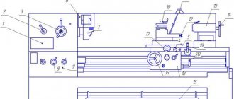
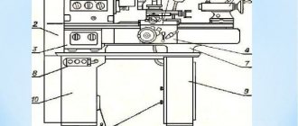
The controls of the 16K20 screw-cutting lathe are shown in Fig. 14. Kinematic diagram of 16K20 is shown in Fig. 15.
Rice. 14. Controls of a high-precision screw-cutting lathe 16K20
Handles:
1 — setting a number of spindle speeds; 2 - settings of spindle speeds, 3 - settings of normal, increased thread pitch and position when dividing multi-start threads, 4 - settings of right and left threads, 5 - settings of feed amount and thread pitch, 6 - settings of the type of work - feed and type of thread being cut , 7 - setting the feed rate and thread pitch and disabling the feed box mechanism, 8 - controlling the friction clutch of the main drive (interlocked with handle 16), 11 - turning the rack and pinion gear on and off, 14 - turning on the feed, 15 - turning the lead screw nut on and off , 16 — control of the friction clutch of the main drive (interlocked with handle 8); 18 - attaching the tailstock to the frame, 19 - gripping the tailstock quill, 20 - controlling the mechanical parameters of the carriage and cross slide of the caliper, 22 - manually moving the cutting slide of the caliper, 23 - rotating and securing the indexable cutting head, 25 - manually moving the transverse slide of the caliper ; buttons: 9 — spool for lubrication of the carriage guides and the transverse slide of the caliper, 12 — turning on and off the electric motor of the main drive, 21 — turning on the electric motor for driving the fast moves of the carriage and the transverse slide of the caliper; flywheels: 10 - manual movement of the carriage, 17 - movement of the tailstock quill; 26 — adjustable coolant supply nozzle; 13 — bolt securing the carriage to the frame; switches: 24-local lighting, 27 - machine load indicator, 28 - coolant supply electric pump switch, 29 - signal lamp, 30 - input circuit breaker.
Kinematic scheme 16K20
The kinematic diagram of the machine is shown in Fig. 70.
Main movement
The main movement in the machine is the rotation of the spindle, which it receives from electric motor I through a V-belt drive with pulleys 2 - 3 and a gearbox. A double-sided friction clutch 6 is installed on the receiving shaft II. To obtain direct rotation of the spindle, the clutch is shifted to the left, and the rotation drive is carried out through the following chain of gears: 4 - 8 or 5-9, 10-13 or 11 - 14. or 12-15, shaft IV, wheels IS -21 or 19 - 22. spindle V. From shaft IV, rotation can be transmitted through selection 16 - 23 or 17 - 24, 25-27 and 26-22 when moving block 21-22 on the spindle to the right. The technical characteristics of the 16K20 make it possible to obtain 12 options for wheel engagement when transmitting rotation from shaft IV directly to the spindle and 12 options when transmitting rotation through the overdrive.
The spindle is reversed by moving the coupling 6 to the right. Then the rotation from shaft II to shaft III is transmitted through gears 7-28, 29-12, and the latter receives reverse rotation.
Rice. 70 Kinematic scheme 16K20
Feed movement
The feed mechanism communicates the movement of the caliper along four kinematic chains: screw-cutting, longitudinal and transverse feed, rapid movement. Rotation of shaft VIII from spindle V is transmitted through gears 20-32, and when cutting threads with an increased pitch from spindle V through the pitch increasing link: wheels 22-26, 27-25, 23-16 or 24-17 and through wheels 16- 33.
From shaft VIII, the movement is transmitted through a reversing mechanism with wheels 30-35 or 31-34-35 to shaft IX, then through replaceable wheels abd or abcd to the input shaft X of the feed box. By switching clutches 116, 60. 43 and 50, as well as rearranging block gears 57 and 58, 45 and 46, 47 and 48, 52 and 53, various combinations of connecting wheels 36...64 of the feed box are carried out. From the output shaft XV of the feed box, rotation can be communicated either to the lead screw 61 or to the lead shaft XVI. In the first case - through clutch 60, in the second - through wheels 59-62, 63-66, overtaking clutch 67 and wheels 68-64.
Screw chain. When cutting a thread, the caliper is fed from the lead screw 61 through the uterine nut fixed in the apron. The required thread pitch can be obtained by switching gears and couplings in the feed box or by installing replacement wheels a, b, c, d on the guitar. In the latter case, clutches 116 and 60 disable the feedbox mechanism. To prevent breakdowns due to accidental overloads, clutch 117 is used.
Longitudinal and transverse feed of the caliper
To transmit the movement of the 16K20 lathe to the apron mechanism, the chassis shaft XVI is used. A gear 65 slides along it along the keyway, transmitting rotation through wheels 69, 70, 71 when clutch 72 is engaged and a worm pair 73-74 to shaft XVII.
To obtain longitudinal feed of the caliper and its reversal, one of the cam clutches - 77 or 84 is turned on. Then the rotation from shaft XVII is transmitted by gears 75-83 - 76 and 79-92 or 85 - 92 to shaft XVIII and then to rack and pinion wheel 94, which, rolling along a rack 95 fixedly connected to the machine bed, it carries out longitudinal movement of the caliper.
Transverse feed and its reversal are carried out by turning on clutches 87 or 90. In this case, from shaft XVII through gears 75-86 and 88-93-98-96 or 75-86-89 and 91-93-98-96, rotation is transmitted to screw 97, which imparts movement to the transverse carriage of the caliper.
Installation movements of the support of a 16K20 screw-cutting lathe, the tool slide and the tailstock quill. To carry out rapid (installation) movement of the caliper, the running shaft XVI is subjected to rapid rotation from the electric motor 113 through the V-belt drive 114-115. In this case, the caliper feed mechanism through the feed box does not need to be turned on, since an overrunning clutch 67 is installed in the drive chain of the drive shaft. Using lead screws 109 and 112, you can manually move the cutting slide and the tailstock quill manually through the wheels 110-111. The machine can be equipped with a mechanical drive of the slide. In this case, from the running shaft XVI through the apron mechanism, wheels 65...98, the wheel 99 of the shaft XIX is connected, and then through the wheels 100...108 the movement is transmitted to the screw 109 of the cutting slide.
Through a V-belt drive 118-119 from the shaft / a lubrication pump 120 is connected.
Setting up the 16K20 kinematic diagram for thread cutting comes down to selecting the gear ratios of feed boxes and other mechanisms, which is done by switching the corresponding levers. An exception is the cutting of particularly precise threads or threads with non-standard pitches. The final link of the thread-cutting chain is the lead screw 55 (see Fig. 69) and the uterine nut, so the adjustment equation can be written in the following form (keeping in mind the single-throw screw):
1 rev.sp. i- tв = tн (8.1)
where tн is the pitch of the thread being cut; tв—lead screw pitch; i is the gear ratio of the kinematic chain from the spindle to the lead screw.
Multi-start thread cutting
Technical characteristics of 16K20 allow you to cut multi-start threads. In multi-start threads, the pitch tn is understood as the distance between the parallel sides of the profile of two adjacent turns. Therefore, to obtain a thread of a given pitch, the feed mechanism must, in one revolution of the workpiece, move the caliper by the amount of thread stroke s = K tн where tн is the number of starts of the thread being cut. This type of thread is cut on lead screws, multi-start worms and other parts.
Multi-start threads are cut in two ways: after cutting the first thread, the workpiece is turned by part of a turn 1/k; Having previously opened the screw-cutting chain or leaving the workpiece motionless, move the tool along with the cutting slide longitudinally by the thread pitch tn. Then the next entry is cut, etc. The 16K20 machine has a special dividing device for cutting multi-start threads. It consists of a ring with a score, mounted on the headstock body, and a disk with divisions, mounted on the spindle and having 60 divisions on the periphery. After cutting the first pass, the spindle must be rotated by a number of divisions equal to 60/k. This device allows you to cut threads with a number of starts of 2, 3, 4, 5, 6, 10, 12, 15, 20, 30, 60. On machines that do not have a dividing device, a driven dividing plate is used.
Processing of shaped surfaces
If in the described copying device a shaped ruler is installed instead of a conical ruler, the cutter will move along a curved path, processing the shaped surface.
Rice. 70 Schematic diagram of the operation of a hydraulic copying support
For processing shaped and stepped shafts, the 16K20 machine is sometimes equipped with hydraulic copying supports, which are most often located on the rear side of the machine support. The lower slide of the support has special guides, usually located at an angle of 45 to the axis of the machine spindle, in which the copying support moves.
In Fig. 70 shows a schematic diagram explaining the operation of the hydraulic copying support. Oil from pump 7 enters the cylinder, rigidly connected to the longitudinal support 5, on which there is a transverse support 2. The latter is connected to the cylinder rod. Oil from the lower cavity of the cylinder through the slot / in the piston enters the upper cavity of the cylinder, and then into the follower spool 6 and into the drain. The follower spool is structurally connected to the caliper. Probe 4 of spool 6 is pressed against copier 3 (in area ab) using a spring (not shown in the diagram). In this position of the dipstick, oil flows through spool 6 to the drain, and transverse caliper 2 moves backward due to the difference in pressure in the lower and upper cavities. At the moment when the probe is in area be, it is recessed under the action of the copier, overcoming the resistance of the spring. In this case, the drain from spool 6 is gradually blocked. Since the area in the lower cavity is larger than in the upper, oil pressure will force caliper 2 to move downwards.
In practice, there are a variety of models of lathes and screw-cutting lathes, from tabletop to heavy-duty ones, with a wide range of sizes. The largest processing diameter on domestic machines ranges from 85 to 5000 mm with a workpiece length from 125 to 24000 mm.
Adjusting the machine 16K20
The video shows the process of setting up the machine and adjusting the spindle assembly.
Similar materials
Analogues of the machine
The 16K20 screw-cutting lathe replaced the 1K62 model, surpassing it in all quality indicators. After it was discontinued, domestic and foreign manufacturers produced numerous analogues of the 16K20 machine with various additions. These are MK6056, MK6057 and MK6058 (Red Proletary, Moscow), 16VT20 and 16VT20P (Vistan, Vitebsk), 16B16, 16B16P, 16B16V and 16B16A (SVZS, Samara) and many other models. Thanks to many analogues and high standardization of parts, there is no shortage of spare parts and equipment to ensure uninterrupted operation of the 16K20 machine.
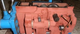
Gearbox 16K20
Gearbox assembly for screw-cutting lathe 16K20. You can also purchase a friction clutch for this gearbox.
Gear boxes are the most common mechanisms for regulating speeds in the main movement drives of universal machine tools. The advantages of gearboxes are as follows: the ability to regulate over a wide range, the ability to transmit significant power, reliable operation, and a constant gear ratio. The disadvantages of such boxes include the impossibility of stepless control, low efficiency, and the difficulty of switching gears on the go. The design of the gearbox is closely related to the design of the spindle drive, and their calculation and design are carried out jointly. According to their design, gearboxes can be divided into three groups:
1) boxes that differ in their location in the machine (in layout); 2) boxes that differ in the method of switching speeds; 3) boxes that differ kinematically.
Speed boxes in their layout and location in the machine are determined mainly by the purpose of the machine and its standard size and, in turn, are divided into three groups:
1) built-in gearboxes; 2) gearboxes, made in the form of an independent unit; 3) attached gearboxes.
Built-in gearboxes . In this case, the gearbox is constructed directly in the spindle head housing near the spindle unit, connected to it by a system of gears and is generally called “spindle head”. This arrangement is used in most general-purpose machines of medium and large sizes due to its compactness, fewer body parts, reduction in the number of castings and parts for butt fitting, and ease of transmission of rotation to the spindle. It should, however, be taken into account that the built-in gearbox serves as a source of harmful vibrations and heat for the spindle assembly, which is unacceptable in precision machines. According to the overall layout, these boxes come with a normal ratio of overall and axial dimensions and with reduced axial or radial dimensions.
a) Spindle heads with a normal ratio between axial and radial overall dimensions are used in small and medium-sized horizontal machines. For this purpose, gears and shaft axles are combined.
b) Headstocks with reduced axial dimensions are most often made due to the development of radial overall dimensions. This arrangement is used for machines with cantilever moving masses (the spindle head moves perpendicular to the spindle axis) in order to eliminate vibrations, in particular for radial drilling and longitudinal milling machines. The vertical layout of the machine also requires a reduction in the axial dimensions of the headstock - to reduce the overall height and vibration.
c) Headstocks with reduced radial dimensions
Due to the development of axial ones, they are used in heavy horizontal lathes and some other groups. This arrangement makes it possible to reduce the transverse dimensions of the machine, and therefore the width of the workshop bay.
Gearboxes made as an independent unit. These boxes are located in a separate housing (gearbox) and are used in machines with the so-called split drive. They eliminate the disadvantages inherent in built-in boxes; they provide smoother spindle rotation and are most often used in precision machines. A divided drive of the main movement in the machine (for example, in a machine type 1A616 (see Fig. 72) is typical for modern high-speed machines. In this case, the spindle head and gearbox are connected by a belt drive; a device is provided for unloading the spindle from the belt tension force. The advantage of this separate drive is as follows: spindle rotation at high speeds is transmitted directly through an elastic belt drive without the participation of gears, which ensures smooth, vibration-free operation of the machine; friction losses in the main drive are reduced due to the reduction in the number of high-speed gears and shaft supports in the kinematic chain; mechanisms controls in the machine are convenient, fast; installation and unification of speed boxes are facilitated. The split drive is widely used in small and medium-sized high-speed and precision machine tools, as well as in machines where it is difficult to place the speed box near the working element. In heavy machines, the split drive loses its advantages and therefore is almost never used. Attached gearboxes . When modernizing outdated models of metal-cutting machines with a step control drive, in order to increase their productivity, speed boxes are used - gearboxes, most often executed in the form of unified attached individual drives. They are installed on the foundation near the machine (directly or on a column) or directly on the machine and connected to the spindle using a belt drive. Unified attached gearboxes are available in four sizes to transmit power at 2.8; 4.5; 7 and 10 ket. To reduce the time it takes to stop the machine, electrical braking is provided in the attached boxes, and the rotation of the spindle is changed by reversing the electric motor. The method of switching gearbox stages is mainly determined by the purpose of the machine and depends on the frequency of switching and the duration of working strokes. In our catalog you will find a wide selection of spare parts and accessories for machines.
The average screw-cutting lathe 16K20 is a successful modification of the legendary Soviet machine 1K62.
Appearing in Soviet-made machine parks half a century ago, it continues to work today in many enterprises, although sometimes there is a need to buy a 16K20 spindle head , or some other unit to replace a worn one. The gearbox or headstock (also called the spindle headstock) includes several important components that determine the operating algorithms of the machine:
- the presence of a friction clutch guarantees three options for turning on the spindle - forward and reverse directions of rotation, as well as stopping with braking;
- the gearbox mechanism allows you to select one of 24 spindle rotation speeds, forming the main movement of the machine;
- The spindle unit ensures spindle rotation in precision bearings, ensuring the specified precision of metalworking.
Thus, the repair of the 16K20 gearbox can be associated both with the loss of the former accuracy of processing parts, and directly with the malfunctions that have arisen. As a rule, it involves a large amount of work, including dismantling, troubleshooting and a number of other operations, the implementation of which should be entrusted to professionals. In addition, only original spare parts must be used during repairs. An alternative to such a repair (usually a major one) is to buy a 16K20 headstock assembly and replace the entire assembly. Our company's catalog offers a wide range of spare parts of original quality. From us, a client can easily buy ready-made assembled units, including such complex and important ones as a spindle head. But the main advantage of our 16K20 gearbox is that you can buy the assembled product from us at the minimum manufacturer price.
