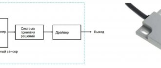
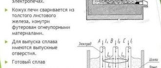
Description of the operating principle and device
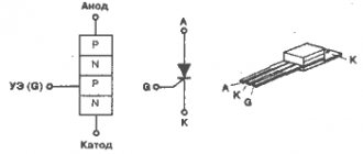
The main difference between these elements and thyristors is the bidirectional conductivity of electric current. Essentially, these are two SCRs with common control, connected back-to-back (see A in Fig. 1).
Rice. 1. Circuit with two thyristors, as an equivalent of a triac, and its conventional graphic designation
This gave the name to the semiconductor device, as a derivative of the phrase “symmetrical thyristors” and was reflected in its UGO. Let us pay attention to the designations of the terminals, since current can be carried in both directions, the designation of the power terminals as Anode and Cathode does not make sense, therefore they are usually designated as “T1” and “T2” (options TE1 and TE2 or A1 and A2 are possible). The control electrode is usually designated “G” (from the English gate).
Now consider the structure of the semiconductor (see Fig. 2.) As can be seen from the diagram, there are five junctions in the device, which allows you to organize two structures: p1-n2-p2-n3 and p2-n2-p1-n1, which, in fact, are two counter-current thyristors connected in parallel.
Rice. 2. Block diagram of a triac
When negative polarity is formed at the power terminal T1, the trinistor effect begins to manifest itself in p2-n2-p1-n1, and when it changes, p1-n2-p2-n3.
Concluding the section on the principle of operation, we present the current-voltage characteristics and the main characteristics of the device.
I-V characteristics of the triac
Designation:
- A – closed state.
- B – open state.
- UDRM (UPR) – maximum permissible voltage level for direct connection.
- URRM (UOB) – maximum reverse voltage level.
- IDRM (IPR) – permissible direct current level
- IRRM (IOB) - permissible level of reverse switching current.
- IN (IUD) – holding current values.
Control signals
To achieve the desired result with a triac, not voltage, but current is used. For the device to open, it must be at a certain low level. For each triac, the strength of the control current can be different; it can be found out from the datasheet for a specific element. For example, for the KU208 triac this current must be more than 160 mA, and for KU201 - at least 70 mA.
The polarity of the control signal must match the polarity of the conditional anode. To control a triac, a switch and a current-limiting resistor are often used, if it is controlled by a microcontroller - you may need to additionally install a transistor so as not to burn the MK output, or use a triac optodriver, such as MOC3041 and the like.
Four-quadrant triacs can be unlocked by a signal of any polarity. This advantage also has a disadvantage - increased control current may be required.
If missing, the device is replaced with two thyristors. In this case, it is necessary to correctly select their parameters and redo the control circuit. After all, the signal will be supplied to two control pins.
Peculiarities
To have a complete understanding of symmetrical thyristors, it is necessary to talk about their strengths and weaknesses. The first include the following factors:
- relatively low cost of devices;
- long service life;
- lack of mechanics (that is, moving contacts that are sources of interference).
The disadvantages of the devices include the following features:
- The need for heat removal is approximately at the rate of 1-1.5 W per 1 A, for example, at a current of 15 A, the power dissipation value will be about 10-22 W, which will require an appropriate radiator. For ease of fastening to it for powerful devices, one of the terminals has a thread for a nut.
Triac with radiator mount
- Devices are subject to transients, noise and interference;
- High switching frequencies are not supported.
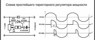
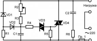
The last two points require a little clarification. In the case of high switching speed, there is a high probability of spontaneous activation of the device. Interference in the form of a voltage surge can also lead to this result. To protect against interference, it is recommended to bypass the device with an RC circuit.
RC circuit to protect the triac from interference
In addition, it is recommended to minimize the length of the wires leading to the controlled output, or alternatively use shielded conductors. It is also practiced to install a shunt resistor between the T1 terminal (TE1 or A1) and the control electrode.
Application
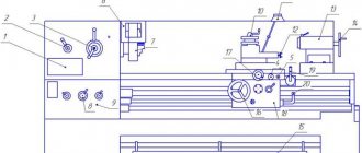
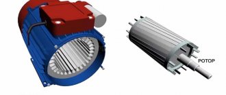
This type of semiconductor elements was originally intended for use in the manufacturing sector, for example, to control electric motors of machine tools or other devices where continuously variable current control is required. Subsequently, when the technical base made it possible to significantly reduce the size of semiconductors, the scope of application of symmetrical thyristors expanded significantly. Today, these devices are used not only in industrial equipment, but also in many household appliances, for example:
- chargers for car batteries;
- household compressor equipment;
- various types of electric heating devices, ranging from electric ovens to microwaves;
- hand-held electric tools (screwdriver, hammer drill, etc.).
And this is not a complete list.
At one time, simple electronic devices were popular that allowed smooth adjustment of lighting levels. Unfortunately, dimmers based on symmetrical thyristors cannot control energy-saving and LED lamps, so these devices are not relevant now.
How to check the functionality of a triac?
You can find several methods online that describe the testing process using a multimeter; those who described them, apparently, have not tried any of the options themselves. In order not to be misleading, you should immediately note that testing with a multimeter will not be possible, since there is not enough current to open the symmetrical SCR. Therefore, we are left with two options:
- Use a pointer ohmmeter or tester (their current strength will be sufficient to trigger).
- Collect a special circuit.
Algorithm for checking with an ohmmeter:
- We connect the probes of the device to terminals T1 and T2 (A1 and A2).
- Set the multiplicity on the ohmmeter x1.
- We carry out a measurement, a positive result will be infinite resistance, otherwise the part is “broken” and can be gotten rid of.
- We continue testing, to do this we briefly connect pins T2 and G (control). The resistance should drop to about 20-80 ohms.
- Change the polarity and repeat the test from steps 3 to 4.
If during the test the result is the same as described in the algorithm, then with a high probability it can be stated that the device is operational.
Note that the part being tested does not have to be dismantled; it is enough to just turn off the control output (naturally, having first de-energized the equipment where the part that raises doubt is installed).
It should be noted that this method does not always allow reliable testing, with the exception of testing for “breakdown”, so let’s move on to the second option and propose two circuits for testing symmetrical thyristors.
We will not give a circuit with a light bulb and a battery in view of the fact that there are enough such circuits on the network. If you are interested in this option, you can look at it in the publication on testing thyristors. Let's give an example of a more effective device.
Circuit of a simple tester for triacs
Designations:
- Resistor R1 – 51 Ohm.
- Capacitors C1 and C2 – 1000 µF x 16 V.
- Diodes - 1N4007 or equivalent, installation of a diode bridge, for example KTs405, is allowed.
- HL bulb – 12 V, 0.5 A.
You can use any transformer with two independent 12 Volt secondary windings.
Verification algorithm:
- Set the switches to their original position (corresponding to the diagram).
- We press SB1, the device under test opens, as indicated by the light bulb.
- Press SB2, the lamp goes out (the device is closed).
- We change the mode of the SA1 switch and repeat pressing SB1, the lamp should light up again.
- We switch SA2, press SB1, then change the position of SA2 again and press SB1 again. The indicator will turn on when the shutter hits minus.
Now let's look at another scheme, only universal, but also not particularly complicated.
Circuit for testing thyristors and triacs
Designations:
- Resistors: R1, R2 and R4 – 470 Ohm; R3 and R5 – 1 kOhm.
- Capacities: C1 and C2 – 100 µF x 10 V.
- Diodes: VD1, VD2, VD5 and VD6 – 2N4148; VD2 and VD3 – AL307.
A 9V battery, Krona type, is used as a power source.
Testing of SCRs is carried out as follows:
- Switch S3 is moved to the position as shown in the diagram (see Fig. 6).
- Briefly press button S2, the element under test will open, which will be signaled by the VD LED
- We change the polarity by setting switch S3 to the middle position (the power is turned off and the LED goes out), then to the bottom.
- Briefly press S2, the LEDs should not light up.
If the result corresponds to the above, then everything is in order with the tested element.
Now let's look at how to check symmetrical thyristors using the assembled circuit:
- We carry out steps 1-4.
- Press the S1 button - the VD LED lights up
That is, when you press the S1 or S2 buttons, the VD1 or VD4 LEDs will light up, depending on the set polarity (the position of the S3 switch).
Diagnostics in diagrams
In some cases, a radio amateur is faced with checking a triac, but cannot always carry it out correctly. If the triac fails, it is advisable to remove it from the board and check it. A regular digital multimeter will not work for this purpose because its current is too low to open the junction of the part. An ordinary pointer ohmmeter is suitable for this. There are only two options for checking: use a pointer device or assemble a special circuit for this operation. To carry out the check according to the first option, you must be guided by the following algorithm:
- Turn the device into resistance measurement mode.
- Connect the tester probes to the emitter and collector. If the device shows infinite resistance, then the part is working. Other cases indicate its malfunction.
- Connect the base and pin T2. In this case, the resistance will be in the range from 40 to 250 Ohms. If you swap the probes, the device will again show infinity. This indicates the serviceability of the triac.
However, the first diagnostic method in some cases gives not entirely necessary and correct results. Very often a part tested in this way in a circuit does not work. This is due to the fact that the seal of its body is broken. The disadvantage of the method is inaccurate diagnosis. For more accurate diagnostics, you should check the triac in operation (Scheme 1). To do this, you need to use an incandescent lamp and a battery.
Scheme 1. Testing a symmetrical thyristor using an incandescent lamp and a power source
In this circuit, the triac will be tested under load. When you touch the control electrode, the light will light up and will remain on for some time until the power at the anode is lost or the current at the base is low. The disadvantage of the method is the simple design, which is inconvenient to carry out testing, since the wires must be soldered to the triac terminals. After checking, if a part is faulty, it should be replaced.
Thus, triacs are used in controlled devices as electronic switches capable of passing current in two directions. They are easy to check and it is advisable to use a special circuit for this operation.