What is a thyristor, its structure and designation on the diagram
A thyristor is a semiconductor element that has only two states: “open” (current flows) and “closed” (no current). Moreover, both states are stable, that is, the transition occurs only under certain conditions. The switching itself occurs very quickly, although not instantly.
In terms of its mode of action, it can be compared to a switch or a key. But the thyristor switches using voltage, and turns off when the current is lost or the load is removed. So the operating principle of a thyristor is not difficult to understand. You can think of it as an electrically controlled key. Well, not really.
A thyristor usually has three outputs. One control and two through which current flows. You can try to briefly describe the principle of operation. When voltage is applied to the control output, the circuit is switched through the anode-collector. That is, it is comparable to a transistor. The only difference is that in a transistor, the amount of current passed depends on the voltage applied to the control terminal. And the thyristor is either completely open or completely closed.
Checking thyristors on the multimeter connector for transistors
Many people are interested in whether it is possible to test a thyristor with a multimeter using the standard socket for testing transistors on the front panel, designated pnp/npn. The answer is yes. You just need to apply the correct voltage. The gain shown on the display will most likely be incorrect. Therefore, avoid being guided by numbers. Let's see how it's done. If the thyristor opens with a positive potential, it must be connected to pin B (base) of the npn half-socket. The anode is plugged into pin C (collector), the cathode is plugged into pin E (emitter). It is unlikely that it will be possible to test a powerful thyristor with a multimeter; for microelectronics, the technique will work.
The essence of the device
The term “thyristor” comes from the merger of two words: the Greek hýra - door or entrance and the English resistor - resisting. This name was given to a semiconductor device made on the basis of a single crystal of a semiconductor substance and having three or more pn junctions. During operation, this device can have two stable positions:
- closed - corresponding to low conductivity;
- open - offering no resistance to the passage of current.
That is, to paraphrase the definitions, we can say that the thyristor works like a key, by analogy with a door. In one of its states, the lock on the door is open, and people can freely pass through it (electric current), and in the other, it is closed and the door is locked. Therefore, it is often called an electronic switch. In scientific terms, its correct name sounds like a semiconductor with a controlled valve (diode).
The adoption of one of the stable states by an element occurs quickly, but not instantly. To change one to the other, voltage is used. When it is present, the thyristor is in the open state, and when not, it closes. For this, a special additional pin is used. Therefore, the device has three outputs and looks like a transistor. At the same time, their principle of operation is similar, only, unlike a transistor, a thyristor either completely passes the current or prevents its passage.
Types of thyristors
Thyristor
A thyristor differs from a bipolar transistor by the presence of a larger number of pn junctions:
- A typical pn junction thyristor contains three. Structures with hole, electronic conductivity alternate in the manner of a zebra. You can come across the concept of npnp thyristor. The control electrode is present or absent. In the latter case we get a dinistor. It works according to the voltage applied between the cathode and the anode: at a certain threshold value it opens, a decline begins, and the flow of electrons is cut off. As for thyristors with electrodes, control is carried out in either of the two middle pn junctions - the collector side or the emitter side. The fundamental difference between the products and the transistor is that the mode remains unchanged after the control pulse disappears. The thyristor remains open until the current drops below a fixed level. Usually called holding current. Allows you to build cost-effective circuits. Explains the popularity of thyristors.
- Triacs differ in the number of pn junctions, which increases by at least one. Capable of passing current in both directions.
Characteristics and parameters
A thyristor is a device that simultaneously combines three functions: a rectifier, a switch and an amplifier. The main properties characterizing the device can be presented in the form of the following points:
- A thyristor, like a diode, passes current only in one direction, that is, it works as a rectifier;
- the device switches from one state to another using voltage;
- the amount of current required to switch a thyristor is on the order of several milliamps, while it can pass tens of amperes through itself;
- By changing the time of the applied signal to the control pin, you can regulate the average value of the current flowing through the load, in other words, control the power.
The main function that describes the operation of the device is the current-voltage characteristic (volt-ampere characteristic). It is a flat coordinate system along the Y axis, on which the load current is plotted, and along the X axis, the voltage on the control electrode. Based on the type of nonlinearity of the correspondence between these two quantities, the current-voltage characteristic belongs to the S-type devices.
The characteristic uses letter designations corresponding to key points in the operation of the thyristor. Thus, the coordinate (Vbo; IL) corresponds to the moment of switching on, and the point with coordinates (Vн; Iл) corresponds to the open state. The zone lying on a segment with coordinates (Vbo; IL) and (Vн; In) is considered transitional, that is, unstable.
A thyristor device, in addition to the current-voltage characteristic, is characterized by a number of parameters:
- The highest constant reverse voltage is the value above which a breakdown of the junction occurs.
- Turn-on voltage is the signal value, upon reaching which the element is unlocked.
- Allowable current is the maximum value that a radio device can pass through without changing its characteristics.
- Holding current is the current flowing through the anode and causing the cell to lock.
- Voltage drop - shows the amount of energy that is dissipated by the device (0.5 -1 V).
- Maximum power is determined by the permissible current and the maximum possible voltage applied to the controlled terminals, that is, the nature of the load.
- Turn-off time is the period of time during which the thyristor will completely close. Amounts to microseconds.
- Opening constant control current - indicates the value that is necessary to maintain the device in the open state (anode-cathode). Typically around 100 mA.
We recommend reading: How to make a tube headphone amplifier with your own hands
Start testing the thyristor with a multimeter
First, take the trouble to determine the location of the electrodes:
- cathode;
- anode;
- control electrode (base).
To open the thyristor switch, the cathode of the device is supplied with a minus (black multimeter probe), and a plus (red multimeter probe) is connected to the anode. The tester is set to ohmmeter mode. The resistance of an open thyristor is low. Stop setting the limit to 2000 Ohms. It's time to remind you: the thyristor is capable of being controlled (opened) by positive or negative pulses. In the first case, we close the anode to the base with a jumper made of a thin pin, in the second - the cathode. Here and there the thyristor should open, as a result the resistance will become less than infinity.
The testing process comes down to understanding what voltage the thyristor is controlled by. Negative or positive. Try this and that (if there is no marking). One attempt will definitely work if the thyristor is working properly.
The process then diverges from testing the transistor. If the control signal disappears, the thyristor will remain open if the current exceeds the holding threshold. The key may close. If the current does not reach the holding threshold.
- The holding current is specified by the technical characteristics of the thyristor. Take the trouble to download complete documentation from the Internet and be aware of things.
- A multimeter determines a lot. What voltage is supplied to the probes (traditionally 5 volts), how much power will it provide. You can check with the help of a large capacitor. You need to correctly connect the probes to the terminals of the device in resistance measurement mode, wait until the numbers on the display increase from zero to infinity. The capacitor has completed the charging process. Now let's switch to the DC voltage measurement mode and see the magnitude of the potential difference on the legs of the capacitor (the multimeter is in resistance measurement mode). Based on the current-voltage characteristics of the thyristor, it is easy to determine whether the value is sufficient to create a holding current.
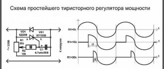
Dinistors ring easier. Try to open the key. Depends on whether the power of the multimeter is enough to overcome the barrier. To guarantee a thyristor test, it is better to assemble a separate circuit. Like the one shown in the picture. The diagram is formed by the following elements:
- Three resistors will serve to set the thyristor mode. One rated at 300 ohms limits the current. If a parameter needs to be changed, it is extremely difficult to overdo it when +5 volts are available. It's okay if you remove the resistor. Try to be guided by the current-voltage characteristics of the thyristor. It is ideal to install a variable resistor with a range of 100 - 1000 Ohms. The two resistors on the right branch set the operating point. In the circuit, 2.5 volts are supplied to the control electrode. If it does not agree with the current-voltage characteristics of the thyristor (see documentation), change the ratings. They form a resistive divider. The 5 volt voltage is divided proportionally to the ratings. Since the resistances are equal to each other, exactly half of the supply voltage reaches the control electrode.
- The LED will serve as a load. It is located in the “power” branch, next to it there is an emitter and a collector. Here, after opening the key, current should flow. The LED will light up, we will see if the thyristor is working. The LED is not infrared. Take the visible range.
Thyristor test circuit
- The thyristor forms the center of the circuit. It is better to solder the sockets into which you can quickly plug in a new test sample. Otherwise, there is no point in planting a vegetable garden. Please note that the circuit is assembled for the case when the thyristor is controlled by a voltage of positive polarity. It is better to find a separate power source. For example, a battery, a PC system unit, an accumulator. The positive pole connects the circuit to ground, the negative pole is fed to the base. Moreover, you will have to remove the resistor from the left branch.
- The button will help you find out with guarantee: the experiment has begun. Without it, control voltage is not supplied. Just press the button and release it, and you will see the result. The LED will light up and go out - the holding current is not maintained, the thyristor is working. Sometimes the LED will remain on, depending on its characteristics.
Why did you choose +5 volt power? The voltage is easy to find on the phone adapter (charger). Take a closer look: there is an inscription like 5V– /420 mA. Output values of voltage, current (immediately see if the thyristor is enough to hold). Every expert knows: +5 volts are available on the USB bus. Almost any gadget, computer, is now equipped with a port (in different formats). Avoid problems with nutrition. Just in case, let's take a closer look at this point.
Device design
Any thyristor device has at least three terminals: anode, cathode and input. They are produced by various manufacturers and can be in the form of a tablet or a pin. As a rule, the material for their manufacture is silicon. It provides good thermal conductivity and can withstand high power.
Emitter junctions are made using alloy technology, and collector junctions are made using the diffusion method. Planar technology is also used. The concentration of impurities in the emitter regions is much greater than in the base regions. In this case, the thickest layer is the central one. These two factors - thickness and low concentration - allow the device to withstand a fairly large reverse voltage (on the order of hundreds of volts). The anode of the device is connected to the body of the product, which ultimately has a positive effect on heat dissipation.
Asymmetrical thyristors have a slightly different design. In their design, the cathode is connected to the n+ and p zone, and the anode to the p+ and n region. Such connections are called anodic or cathodic short circuits. Their use leads to the appearance of additional resistance between the transitions. This connection reduces transient processes and the lifetime of the main carriers.
The simplest design of a thyristor includes a base connected to a semiconductor crystal and serving as an anode, a cathode terminal, and a control electrode. On top of the crystal is covered with an insulator and a lid, which helps protect the device from mechanical damage and at the same time serves as a heat sink.
Purpose of the device
Thyristors are semiconductor devices with three (or more) pn junctions intended for use as electronic switches in electrical current switching circuits. They switch electrical circuits, regulate voltage, and convert direct current into alternating current.
In design and principle of operation, it is very similar to a semiconductor diode, but unlike it, the thyristor is controlled. The “key” nature of the action of the trinistor allows it to be used for switching electrical circuits where previously only electromagnetic relays served for this purpose.
Semiconductor switches are lighter, more compact and many times more reliable in operation than electromagnetic relays with mechanically closed contacts. Unlike such relays, they switch at a very high speed - hundreds and thousands of times per second, and if necessary - even faster. SCRs are used in modern electrical communication equipment, in high-speed remote control systems, in computers and in energy devices.
Types of thyristors
Lockable ones were discussed above, but there are many more types of semiconductor thyristors that are also worth mentioning. Certain types of thyristors are used in a variety of designs (chargers, switches, power regulators). Somewhere it is required that control be carried out by supplying a stream of light, which means an optothyristor is used. Its peculiarity is that the control circuit uses a semiconductor crystal that is sensitive to light. The parameters of thyristors are different, they all have their own characteristics that are characteristic only of them. Therefore, you need to at least have a general idea of what types of these semiconductors exist and where they can be used. So, here is the entire list and the main features of each type:
- Thyristor diode. The equivalent of this element is a thyristor, to which a semiconductor diode is connected back-to-back.
- Dinistor (diode thyristor). It can go into full conduction if a certain voltage level is exceeded.
- Triac (symmetrical thyristor). Its equivalent is two thyristors connected back-to-back.
- The high-speed inverter thyristor has a high switching speed (5... 50 μs).
- Thyristors with field effect transistor control. You can often find designs based on MOS transistors.
- Optical thyristors that are controlled by light flows.
Types of thyristors, their differences and connection diagrams
Based on the two types considered, several more types of thyristors are produced. Each of them has its own scope of use.
Dinistors
The dinistor is connected to the circuit like a regular diode in series with the load. Nutrition can be constant or variable.
Symmetrical dinistors (bidirectional dinistors, diacs), which are two conventional devices connected back to back, also work in an alternating voltage circuit. They open from any half-wave of sinusoidal voltage. The current-voltage characteristic of the diac is symmetrical - the reverse branch is also located in the III quadrant and mirrors the direct one.
SCR
The most common type in this category of semiconductor devices. In a professional environment, triode thyristors are simply called thyristors, although this is fundamentally incorrect. The thyristor is also included in the circuit like a conventional diode (in a direct or alternating voltage circuit). Unlocking occurs when a positive voltage is applied to the UE (coincident in sign with the anode voltage during direct connection). In two-operation devices, locking is carried out by supplying the UE with a current in the opposite direction.
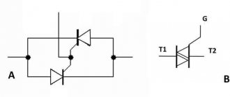
Triacs
Along with symmetrical dinistors, there are also symmetrical trinistors (triacs, triacs). They are two thyristors with common control, connected back-to-back and placed in one housing. If necessary, the triac can be replaced with two separate devices by connecting them according to the appropriate circuit.
The current-voltage characteristic of the triac is also symmetrical about zero.
Optothyristors
There are devices similar in structure and principle of operation to conventional thyristors, but which are unlocked by light incident on the open thyristor structure. If you combine such a switch and an LED controlled by an external signal source in one housing, you get a device called an optothyristor (thyristor optocoupler).
Principle of operation
Thyristors are essentially switching devices. The structure of a simple element consists of npnp layers and has three transitions. Two of them work in the forward direction, and one in the reverse direction. The device has two outer regions called anode (p) and cathode (n). To understand the principle of operation of a thyristor, it can be represented as dual transistors: npn and pnp. In this case, the middle zone of the second transistor (n) is connected to the outer zone of the first.
We recommend reading: Simple diagrams for beginner radio amateurs
As a result, it turns out that the outer zones will be emitter junctions, and the middle zones will be collector junctions. The base area of the first element will coincide with the collector of the second and vice versa. Based on this, the collector current of the transistors will also be the base current.
The physical processes occurring in the element can be described as follows. If there was only one junction in the device, only a reverse current would arise, caused by minority charge carriers. If a direct voltage is applied to the emitter junction, the collector current will increase and the voltage across it will decrease. In a transistor, to switch it to saturation mode (maximum throughput), a direct voltage is applied to the emitter, and between the base and collector it is reduced to single values.
Same thing in a thyristor. Minority charges are injected through the junctions of the anode and cathode, leading to a decrease in the resistance of the control electrode. When direct voltage is applied, that is, a negative potential is applied to the cathode, and a positive potential is applied to the anode, a small current begins to flow through the device. This state corresponds to the closed position.
An increase in voltage leads to the injection of carriers into the controlled junction. As a result, on the one hand, its resistance increases due to depletion of the majority carriers, since the junction turns on in the opposite direction, and on the other hand, it increases due to the entry of new charges into its region.
When the voltage reaches a certain value, these two phenomena are balanced, and even an increase in voltage by a small amount leads to an avalanche-like process of unlocking the thyristor. This state resembles the saturation mode of a transistor. The junction resistance becomes minimal, and the current value is determined by the load resistance.
Thyristor operating modes
The thyristor has three operating modes:
- Forward lock
- Reverse blocking
- Forward conduction
Forward lock
In this state or mode, forward conduction of current is blocked. The top diode and bottom diode are forward biased and the junction in the center is reverse biased. Thus, the thyristor does not turn on because the gate does not fire and no current flows through it.
Reverse blocking
In this mode, the connection between the anode and cathode is reversed and no current flows through it. Thyristors can only conduct current in one direction and it blocks in the opposite direction, so the flow of current is blocked.
Forward conduction
When current is applied to the gate, the thyristor is triggered and it begins to conduct current. It remains on until the forward current drops below a threshold, and this can be achieved by turning off the circuit.
DC circuit
In a direct current circuit, a thyristor operates on the principle of delivering a pulse of positive polarity, of course, relative to the cathode. The duration of the transition from one state to another is greatly influenced by a number of characteristics. Namely:
- Type of load (inductive, active, etc.).
- The rate of rise of the pulse and its amplitude, meaning the load current.
- The magnitude of the current load itself.
- Voltage in the circuit.
- The temperature of the device itself.
The most important thing here is that there is no sudden increase in voltage in the network where this device is installed. In this case, the thyristor may turn on spontaneously, and the control signal will be absent at this time
AC circuit
In this network, the thyristor switch works a little differently. This device makes it possible to perform several types of operations. Eg:
- Switching on and off a circuit in which an active or active-reactive load acts.
- You can change the value of the effective load and its average value due to the ability to change (adjust) the supply of the control signal itself.
Thyristor in an alternating current circuit.
But keep in mind that a thyristor switch can only pass a signal in one direction. Therefore, the thyristors themselves are installed in the circuit, so to speak, in an anti-parallel connection.
Two-transistor analogy of a thyristor
The collector current from the NPN transistor is supplied directly to the base of the PNP transistor and the collector current of the PNP transistor is supplied to the base of the NPN transistor. These connected transistors rely on each other for conduction.
Thus, a base current is required to conduct one of the transistors. When the anode terminal of the thyristor is negative with respect to the cathode, the NP junction becomes forward biased and the PN junction becomes reverse biased.
We recommend reading: Twisted pair: what is it, crimping diagram
Two transistor analogues of a thyristor
Here the reverse current flow is blocked until the breakdown voltage is applied. After the breakdown voltage, it begins to conduct without a gate signal being applied. This is one of the negative characteristics of thyristors, since it triggers conduction when the voltage is reversed.
When the anode terminal is made positive with respect to the cathode, the outer junctions are forward biased and the central NP junction is reverse biased and blocks forward current. Thus, to induce it into conduction, a positive current is applied to the base of the transistors.
The two transistors are connected in a regenerative circuit and this causes the transistor to conduct saturation. Thus, we can say that thyristors block current both in the direction of the AC source in the off state, and can be turned on by applying a positive current to the base of the transistor.
Thyristors for dummies
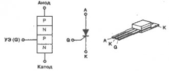
Good evening habr. Let's talk about such a device as a thyristor. A thyristor is a bistable semiconductor device having three or more interacting rectifying junctions. In terms of functionality, they can be compared to electronic keys. But there is one feature in the thyristor: it cannot go into the closed state, unlike a regular key. Therefore, it can usually be found under the name - not fully managed key. The figure shows a typical view of a thyristor. It consists of four alternating types of electrical conductivity of semiconductor regions and has three terminals: anode, cathode and control electrode. The anode is in contact with the outer p-layer, the cathode is in contact with the outer n-layer. You can refresh your memory about pn junction here.
Classification
Depending on the number of pins, a classification of thyristors can be derived. In essence, everything is very simple: a thyristor with two terminals is called a dinistor (accordingly, it has only an anode and a cathode). Thyristors with three and four terminals are called triode or tetrode. There are also thyristors with a large number of alternating semiconductor regions. One of the most interesting is a symmetrical thyristor (triac), which turns on at any voltage polarity.
Principle of operation
Typically, a thyristor is represented as two transistors connected to each other, each of which operates in active mode.
In connection with this pattern, the outer regions can be called emitter, and the central junction can be called collector. To understand how a thyristor works, you should look at the current-voltage characteristic.
A small positive voltage is applied to the anode of the thyristor. The emitter junctions are connected in the forward direction, and the collector junctions in the reverse direction. (essentially all the tension will be on it). The section from zero to one on the current-voltage characteristic will be approximately similar to the reverse branch of the diode characteristic. This mode can be called the thyristor closed state mode. As the anode voltage increases, majority carriers are injected into the base region, thereby accumulating electrons and holes, which is equivalent to the potential difference at the collector junction. As the current through the thyristor increases, the voltage at the collector junction will begin to decrease. And when it decreases to a certain value, our thyristor will go into a state of negative differential resistance (section 1-2 in the figure). After this, all three transitions will shift in the forward direction, thereby transferring the thyristor to the open state (section 2-3 in the figure). The thyristor will remain in the open state as long as the collector junction is biased in the forward direction. If the thyristor current is reduced, then as a result of recombination the number of nonequilibrium carriers in the base regions will decrease and the collector junction will be biased in the opposite direction and the thyristor will go into the off state. When the thyristor is turned on in reverse, the current-voltage characteristic will be similar to that of two diodes connected in series. The reverse voltage will be limited in this case by the breakdown voltage.
General parameters of thyristors
1. Turn-on voltage
is the minimum anode voltage at which the thyristor goes into the on state.
2. Forward voltage
is the forward voltage drop at maximum anode current.
3. Reverse voltage
is the maximum permissible voltage on the thyristor in the closed state.
4. The maximum permissible forward current
is the maximum on-state current.
5. Reverse current
- current at maximum reverse voltage.
6. Maximum electrode control current
7.
On/off delay time
8.
Maximum permissible power dissipation
Conclusion
Thus, there is a positive current feedback in the thyristor - an increase in current through one emitter junction leads to an increase in current through the other emitter junction.
A thyristor is not a complete control switch. That is, having switched to an open state, it remains in it even if you stop sending a signal to the control transition, if a current above a certain value is supplied, that is, the holding current. Sources:
ru.wikipedia.org electricalschool.info
Classification characteristics
According to the control method, the following types of thyristors are distinguished:
Diode (dinistors)
They are activated by a high voltage pulse applied to the anode and cathode. The design contains 2 electrodes, without a control one.
Triode (sCR)
They are divided into two groups. In the first, the control voltage is supplied to the cathode and the control electrode, in the second - to the anode and the control electrode.
Triacs
Perform the functions of two thyristors connected in parallel.
Optothyristors
Their functioning is carried out under the influence of light flux. The function of the control electrode is performed by a photocell.
According to reverse conductivity, thyristors are divided into:
- reverse conductive;
- reverse non-conductive;
- with non-standardized reverse voltage value;
- passing currents in two directions.
Application of thyristor
The purpose of thyristors can be very different, for example, a homemade welding inverter using thyristors, a charger for a car (thyristor in the power supply) and even a generator are very popular. Due to the fact that the device itself can pass both low-frequency and high-frequency loads, it can also be used for a transformer for welding machines (their bridge uses exactly these parts). To control the operation of the part in this case, a voltage regulator on the thyristor is needed.
Photo - using Thyristor instead of LATR
Don't forget about the ignition thyristor for motorcycles.