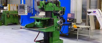
Basics of the Milling Process
In almost all large industrial production and small workshops you can find milling machines. After all, milling is the most popular method of mechanical processing of products. Milling devices are used to perform rough, semi-finishing and finishing machining of workpieces made of wood, ferrous and non-ferrous metals, as well as plastic. Modern machines are capable of quickly and accurately processing products of not only simple, but also the most complex shapes.
Milling machines are divided into two types:
- General purpose machines.
- Specialized equipment.
The specialized equipment includes the copy milling cutters in question. They allow you to make copies of objects and work with both flat and three-dimensional shapes. Moreover, these devices can help to engrave, apply ornaments, various inscriptions, and create various patterns on edges that are located in different planes.
There are two milling methods:
- Counter, in which the tool is fed and rotated in different directions.
- Incidental. In this case, the feed and rotation of the tool occur in different directions.
The cutting blade of cutters of such machines can be made of a variety of materials, which allows you to successfully switch from processing wooden products to hard metals and even natural or artificial stones.
Purpose
Often, a copy-milling machine is used to perform volumetric and plane processing; its operation is similar to those on which the CNC system is installed. At the same time, special models allow wood processing to be carried out in volume when a volumetric model is used as a copier. In the woodworking industry, volumetric processing allows:
- create ornaments and various inscriptions.
- engrave shaped profiles.
- create complex patterns, the edges or planes of which are located in different planes.
The woodworking machine in question is often used in furniture production. Many decorative parts that have complex shapes are created using a similar machine.
Work principles
The common element for all copy routers for wood or metal is the milling cutter - a cutting and processing tool.
Key points of operation of the milling device:
Using a copier, a surface or contour is specified, which is then followed by a cutter.- Between the tracking unit and the cutting cutter there is a system connecting them. When processing wooden products, it most often has mechanical control and feed. In addition to the mechanical system, a pneumatic or hydraulic system is used.
- The copier can be either a flat template, or a reference volumetric blank, a photocell or a drawing. CNC is built into complex machines, and then they become widely universal.
- The parts that act as templates can be made from anything. It can be wood, metal, plastic or other dense material.
All copying machines operate on the same principle: a tracking device is connected to a sample of any type, which, through a connecting system, transmits the necessary direction and force to the cutting unit - the milling cutter.
The use of a sample template eliminates manual intervention and therefore, even when making copies of complex parts, all resulting products are the same in shape and size. Copy milling can be contour, volumetric or direct. The workpiece being processed and the initial template are fixed on the moving working surface of the machine.
When contour copying, the working surface moves in the longitudinal direction. In the second case, during volumetric copying, the table with the copier and the workpiece are movable in both the transverse and longitudinal directions.
The unit between the copier and the cutter, which precisely sets the movement and force of the cutting tool, is called a pantograph. On wood or other materials, pantographs work equally flawlessly.
The pantograph is used in direct action machines. This unit allows you to organize not only copying, but also scaling of parts. Often such machines are used for engraving work.
The pantograph consists of a guide pin, its axis, a separate axis of rotation and a tool spindle. The guide pin and the spindle are placed on one bar. The copying scale directly depends on the ratio of the spindle arms and the pin.
The finger moves along the contour of the original and sets in motion the rack, which rotates freely on an axis. Thus, the spindle located on the other side of the rack follows the movement of the finger.
The cutting edge is driven by a screw, a spool valve, a solenoid, and an electromagnetic clutch. A relay is used in the amplification device of a metal copy milling machine. It can be electromagnetic, hydraulic or electro-optical.
Rotation is transmitted from an electric motor using a chain and a hydraulic cylinder.
The transmission of torque can be multi-stage.
The quality of the part obtained by copying, namely roughness, dimensional and shape accuracy, directly depends on the speed of response and movement of the tracking device. Good results are considered: profile accuracy is two hundredths of a millimeter, and the roughness must correspond to the sixth number of generally accepted standards.
Classification
- wood pantograph for router. this option can work in 2 or 3 dimensions;
- universal type, which is also called a pantograph, having a rotating arm. as a rule, the sleeve is located in a vertical plane;
- There are design options that have several spindles to speed up the processing process;
- with mechanical, electrical, hydraulic feed;
- photocopy type of contour transfer for guiding the cutting tool.
Woodworking machines also differ in the level of automation of the production process. In this case, CNC is installed quite rarely, since the template processing method does not require a Numerical Program Control system to indicate the trajectory of the cutting tool.
Types of devices
Copying equipment may differ in drives, which come in different types.
Based on the drives, they are distinguished:
- Devices that have a pantograph, which allows you to process parts in different dimensions.
- Equipment in which the copier is mounted on a rotating bar that is movable vertically.
- Machines with rotary tables. The device may have one spindle or several. The table has a round or rectangular shape.
- Photocopiers.
- Equipment with feeding due to mechanical, hydraulic or electrical components.
The machines also differ in the degree of automation and options for fixing workpieces.
Based on this device there are:
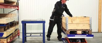
- Tabletop or handheld. The workpiece is fixed mechanically. This method allows you to drill holes on a workpiece according to a given pattern.
- Automatic machines on which workpieces are fixed with pneumatic clamps. These machines are stationary and work with aluminum.
- Automatic stationary units with pneumatic springs and a three-spindle head. With this design, it is possible to simultaneously drill triple holes, which is impossible to do with previous types of devices.
On the modern market there are many offers for ready-made machines of various levels and complexity. But some craftsmen prefer to make homemade copy milling machines for wood or metal. If there are drawings, tools and source material, then such equipment is not difficult to assemble.
Conclusion
Copying and milling equipment with a pantograph greatly facilitates and simplifies the production of wooden products with complex shapes and reliefs. Without them, such production would take much more time and labor.
After watching the video in this article, you will gain additional knowledge on the topic discussed, which is quite complex. If you don’t understand anything or have any questions, you can ask us in the comments to the article.
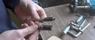
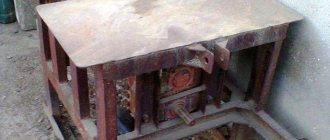
DIY making
A homemade wood carving copying machine, of course, cannot fully compete with industrial designs. When using homemade devices, various disadvantages are observed.
The most common problems are vibration of the machine frame, sagging of the workpiece, and large errors when copying. Therefore, when designing your own machine, you should take into account the tasks that it will solve. It is easier to assemble a narrow-profile device than a universal one, immediately setting it up to solve the same type of problem.
Despite the variety of diagrams showing the order of assembly of the machine, all devices have the same basic components.
The minimum set of elements is as follows:
- Working desk.
- Bearing frame.
- Milling head.
Rotation from the electric motor is transmitted through the drive to the head with the cutter. If it is necessary to change the cutting mode, the height of the table changes. If desired, a transmission mechanism is developed to change speeds.
The pantograph can be assembled from wood or metal.
The wood pantograph has its drawback, since the wooden parts are connected using hinges and, thus, they are characterized by backlash. Therefore, the processing accuracy of a wooden pantograph is low.
When making a metal pantograph, it becomes possible to create copies of different scales. But he doesn't know how to make large copies.
Some craftsmen are trying to remake an ordinary production milling machine by adding a copying device to it. In this case, it is necessary to remake almost the entire old machine and it is easier to assemble the unit from scratch.
The size of the workpieces that the machine will have to process should be taken into account. The greater the length of the workpiece, the greater the load on the guide axis of the machine. They may not be able to withstand such a load. And also when working with large parts, the tool experiences large vibrations. To compensate for the moment of vibration, the equipment must be designed massive and heavy.
Therefore, first of all, before creating a copy milling machine for metal or wood, you need to highlight the tasks that will be solved when working on it. Based on this, the dimensions of the table and the entire structure, methods of attaching the template and options for moving the cutter are planned.
If you plan to process flat parts, then two machine axes will be enough for contour copying, since the movement will only be longitudinal and transverse.
If you expect to work with embossed workpieces, you will need to add a perpendicular movement.
If the relief is large, then you have to rely on one more axis - the fourth.
All possible options must be thought through before starting production of the machine, since after manufacturing and assembling all the components, it is very difficult to make changes to the existing design.
The layout of the machine can be horizontal or vertical. If the machine is vertical, then during milling the chips fall either onto the table or into a special tray, and do not settle in the parts of the cutter.
For better quality of product processing, the milling head must be high-speed.
To process parts made of different materials, it is advisable to have a set of cutting cutters of different quality and wear resistance.
After determining the range of tasks, the required motor power is calculated. To perform engraving and similar work on wood, a motor with a power of one hundred and fifty to two hundred watts is sufficient.
The working unit and the probe are fixed together so that they are on the same plane and height in relation to the working table. A rigid clamp is used as fastening. Then the entire assembled element will be able to move parallel to the sides of the working surface, both horizontally and vertically.
All moving parts must be as light as possible so that control forces are minimal.
Capabilities of copy-milling equipment
The copying machine, which belongs to the milling group, is designed for copying and milling work with flat and three-dimensional parts. In addition, such a device can be used to engrave shaped profiles, apply inscriptions and patterns (even of high complexity) to products, and carry out light milling operations on wood and other materials.
Using tools with cutting parts made of various materials, parts made of cast iron, different types of steel and non-ferrous metals are processed on copy milling machines. Such devices for producing parts in small and large batches successfully produce blades for turbojet engines and steam turbines, propellers for ships, cutting and forging dies, impellers for hydraulic turbines, molds for pressing and casting, molds, etc.
A copy-milling machine performs technological operations that are practically inaccessible to universal equipment. The operating principle of such a machine is based on the copying method, for which a special template is used. The use of a template eliminates the human factor when processing even the most complex parts, due to which all finished products have the same shape and geometric dimensions. Conveniently, one template can be used to accurately manufacture a large batch of parts that will be completely identical to each other.
In order to copy the shape and dimensions of the template as accurately as possible, a copier (pantograph for a router) is installed on a copy-milling machine. The purpose of such a device is to accurately transfer all movements from the copy head to the cutting tool.
Safety regulations
Since the tool is both electric and cutting, it requires careful operation and compliance with basic safety rules.
Safety guidelines include:
- The device should be placed indoors in such a way that it is easily accessible.
- The room itself should be well ventilated.
- Before turning it on, you need to make sure that the table surface is free of unnecessary objects and nothing interferes with the operation of the device.
- All fasteners, especially the cutter, must be securely fastened and not loose.
- The electric motor must be grounded and not damaged.
- Do not touch rotating shafts with your hands until they come to a complete stop.
- Any repair work is carried out only with the device turned off and the engine disconnected from the mains.
- You need to stand on a rubber mat while working.
- After half an hour of continuous operation, it is necessary to turn off the machine and allow the parts to cool.
Knowing and following simple safety precautions prevents injuries, cuts, bruises, and sometimes saves lives.
How does a copy milling machine work?
As noted above, on a copy-milling machine the workpiece is processed using a master device - a copier. All movements of the copier along the contour or surface of the template are transmitted thanks to a special (copying) device to the working head of the machine in which the cutter is fixed. Thus, the cutting tool exactly repeats all the movements made by the copier used to equip the router.
The movements of the elements of a copy-milling machine during the processing of a part are divided into main (rotation and movement of the spindle when cutting the tool into the workpiece material, movement along the contour of the work table and slide) and auxiliary (movement of the spindle head, slide and table in accelerated mode, as well as installation movements made by the tracer table, the copying finger, the stops and the clamp that secures the spindle head).
In copy milling machines working on aluminum, two tracking schemes can be implemented: simple action and feedback action. When implementing the direct action scheme, the working body of the machine makes movements due to the fact that it is rigidly connected to the copier. The reverse action scheme does not provide for such a connection and movements from the copier to the working element are transmitted not directly, but through a tracking system.
As mentioned above, contour and volumetric milling is performed on copy milling machines. When contour milling, the movements of the copier occur in a plane parallel or perpendicular to the axis of the tool. In the first case, the movement of the equipment working table can only be longitudinal, and the cutter and copying finger move vertically. In the second case, the table moves both longitudinally and transversely. In volumetric milling, the part is processed in stages - thanks to several movements of the table and tool performed in parallel planes.
The direct action scheme can also be implemented through a pantograph, which allows you to reduce the size of finished products in relation to the size of the template used (scale). Most often, such an additional device, which is easy to make yourself, is installed on machines used for engraving and light milling work.
Another variation of a self-made machine