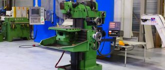
The spindle of a CNC milling machine is the most important structural element of such equipment. The cutting tool is fixed in this part, and it is this part that transmits rotation to it.
CNC milling machine spindles placed on a movable gantry
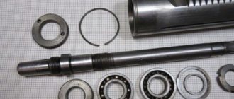
Detailing of main components
The bed is designed for the correct and stable location of the main components (headstocks) during any load during operation. In metal-cutting machines, the bed can have a vertical or horizontal position. Basic requirements for a frame of any design:
- vibration resistance;
- rigidity;
- heat resistance.
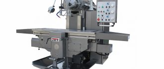
Many types of machines are equipped with a traverse or cross beam that moves on vertical rails. The traverse has horizontal rails along which mobile units move. This mechanism is equipped with longitudinal milling, rotary turning, planing, radial drilling machines. Two-column vertical turning lathes are additionally equipped with a portal - a crossbar between the upper points of the racks. The portal gives the structure additional rigidity.
Guides are of great importance for the accuracy of parts; mobile units move along them.
There are several types of guides:
- rolling;
- slip;
- combined.
The guides wear out quickly, so increased attention is paid to the selection of material and manufacturing of these units. Gray cast iron, steel, bronze, plastics, composites are used
Making a wood milling machine
The production of equipment must be carried out strictly according to a pre-designed scheme. It indicates the location of each component, how it is attached and its dimensions.
At the first stage of manufacturing, it is necessary to assemble the support frame for the machine. To do this, pre-prepared pipe blanks should be connected to each other. Then they are fixed using welding. After this, the dimensions of the top part are checked and the production of the tabletop begins.
- Markings are applied to the fiberboard panels, according to which the outline of the tabletop is cut out.
- When positioned vertically, the cutter makes a hole in the panel.
- Installation of the electric motor and spindle. The latter should not protrude above the plane of the tabletop.
- Installation of limit strip.
After this, the first design tests can be carried out.
It is important that there are no strong vibrations during operation. To compensate for them, additional stiffeners can be installed
Adjustment and Settings
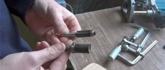
On traditional machines with a spindle fixed in one position, engine speed adjustment is carried out in a classic, mechanical way, using a gearbox. The image shows the spindle speed adjustment lever on a traditional router:
On spindles with a built-in electric motor, adjustment is performed electrically by decreasing and increasing the current supplied to the electric motor.
The spindle itself does not require special settings before operation. Attention is paid to the correct positioning and secure fastening of the cutter, according to the operating instructions for each machine. An incorrectly inserted cutter may not cut at the intended depth or may jump out of the clamp during operation.
Cone angle
An important indicator when constructing various drawings is the cone angle. It is determined by the ratio of the large diameter to the smaller one. This indicator is calculated for the following reasons:
- At the time of processing, the master must take this indicator into account, since it allows him to obtain the required product with high dimensional accuracy. In most cases, processing is carried out taking into account the angle, and not the indicators of large and small diameter.
- The cone angle is calculated at the time of project development. This indicator is plotted on the drawing or displayed in a special table, which contains all the necessary information. The machine operator or foreman does not carry out calculations at the production site; all information must be indicated in the developed technological map.
- Checking the quality of a product is often carried out on a small and large basis, but tools can also be used to determine the taper index.
As previously noted, in the mechanical engineering field the indicator is standardized. In another area, the value may differ significantly from established standards. Some products are characterized by a stepped surface arrangement. In this case, it is quite difficult to carry out calculations, since there is an intermediate diameter.
Features of the spindle depending on the type
Basically, during the operation of milling machines, all loads are perpendicular to the spindle axis, and parallel loads appear only at the moment of cutting into the body of the workpiece. That is why it is necessary to choose an engine that can withstand such loads over a long period of time, since the operation of milling machines can be continuous for a day or even more.
Spindles intended for industrial purposes do not require constant cleaning and lubrication of bearings throughout their entire service life, but if you begin to notice extraneous sounds in its operation at idle, it is still better to disassemble the motor housing and blow out all contaminants from the inside with compressed air (if such are present) and lubricate the bearing well with a special lubricant that does not lose its properties at high temperatures.
Collet clamps
Basically, the most common are collets of the ER11 and ER16 types, into which a drill or cutter with a shank diameter of 2.5 to 3.2 mm is inserted, even if it is made with a cone. There are also chucks designed for a larger tool diameter, but they are used for rough metal processing or steel milling and have a hole for tool clamping of 6 millimeters or more.
Spindle selection by power
Often, a spindle needs to be selected for a machine that performs a certain type of work, so the required power parameter can tell you what type of device you should buy.
Each type of machine work requires different equipment power.
Drilling and engraving requires 1.5 kW of spindle power.
Cutting (and the whole range of milling work) on wood - from 2.2 kW to 4.5 kW.
Processing hardwood requires at least 3.5 kW of device power.
Main design features
A universal screw-cutting lathe consists of main structural units, which are standard elements. These include:
- caliper;
- bed;
- thrust and spindle headstock;
- electrical equipment;
- drive shaft;
- guitar gears;
- a box that provides selection and change of feeds;
- lead screw - it is this detail that distinguishes a screw-cutting lathe from a standard lathe.
Depending on some features, the accuracy of the machine may vary. Therefore, universal equipment can be of both accuracy class N and increased – P.
Front and rear stock
The headstock or spindle has the main role of fixing the workpiece in processing and transmitting rotation to the workpiece from the electric motor.
The spindle is located inside the body of the headstock. A speed control handle is mounted on the outside of the machine body. The tailstock or thrust is necessary to fix the workpiece.
Caliper
The support is designed to move the tool holder with the cutter in the longitudinal, transverse direction relative to the axis of the machine. The lower part of the support is called the slide or carriage.
After a certain time of operation of the machine, the support will need to be adjusted, since otherwise the processing speed will decrease. Adjustment for gaps consists of tightening the wedge strip.
Compared to other parts, the caliper is large. The choice of tool holder is determined by the class of the machine. For large equipment, be sure to secure the cutters with an additional four screws.
Gearbox
This is the main part of the spindle drive. It transmits engine energy to the rest of the machine. Another function is to change the spindle speed and the operating speed of the entire machine.
The box is built into the spindle head housing or in a separate housing block. The speed can be changed in a stepless or stepwise manner. The standard gearbox includes the following components:
- gear system;
- V-belt transmission;
- reversible electric motor;
- electromagnetic clutch with braking system;
- handle for changing gears.
The gearbox operates using gears.
Spindle
This is the main part of the machine, which is made in the form of a shaft with a conical hole for securing workpieces. To ensure that the part has high strength and durability, it is made of high-strength steel.
In the classic version, the spindle is made on high-precision rolling bearings. A special ring is installed on the support of the part, which ensures the accuracy of the machine.
There is a conical hole at the end of the structure. The spindle needs a cavity to install a rod that helps, if necessary, knock the center out of the seat.
The strength and durability of the spindle directly depends on the bearings available there.
bed
This is the main part of the machine, which is made using cast iron. All the most important parts and elements of this design are attached to it.
The frame itself consists of two steel beams. The beams, in turn, are connected to each other by stiffening ribs. Each beam has a connection to two guides.
The guides on both sides belong to the prismatic group. The flat-shaped guide is located inside on the left side.
Threading
There are several ways to cut threads using a screw-cutting lathe. For this, a die, tap, cutter and other types of tools are used.
With their help it is possible to cut internal and external threads
When using a cutter, it is important to fully comply with the technology. It includes:
- correct sharpening of the cutter;
- accurate adjustment of machine operating modes;
- using a template, correct installation of the cutter in the center of the part;
- measuring the resulting dimensions using gauges or templates.
In such work, defects in the form of sharp points, torn threads, scuffing and crushing are unacceptable.
Electrical control unit
The standard control unit for a screw-cutting lathe includes several handles and buttons:
- handle for setting the number of revolutions;
- control system for setting cutting surface parameters;
- handles for caliper control.
A CNC machine has a more complex structure, but can work without operator participation at intermediate stages.
Apron
In the apron of a screw-cutting lathe there are mechanisms that convert the rotational movement of the lead screw and the lead shaft into the translational movement of the caliper.
Caliper structure
Creating a CNC milling machine for metal with your own hands
The support of a lathe is a unit that ensures the fixation of the cutting tool, as well as its movement in the inclined, longitudinal and transverse directions. It is on the support that the tool holder is located, moving with it due to a manual or mechanical drive.
Support with carriage for machine Optimum D140x250
The movement of this unit is ensured by its structure, which is characteristic of all lathes.
- The longitudinal movement, for which the lead screw is responsible, is performed by the caliper carriage, while it moves along the longitudinal guides of the frame.
- Transverse movement is performed by the upper - rotating - part of the support, on which the tool holder is installed (such movement, due to which the depth of processing can be adjusted, is carried out along the transverse guides of the support itself, which are shaped like a dovetail).
Quick-change tool holder MULTIFIX cartridge type
The tool holder, also called the cutting head, is installed on the top of the support. The latter can be fixed at different angles using special nuts. Depending on the need, single or multiple tool holders can be installed on lathes. The body of a typical cutting head has a cylindrical shape, and the tool is inserted into a special side slot in it and secured with bolts. There is a protrusion on the bottom of the cutting head that fits into a corresponding slot on the support. This is the most typical tool holder mounting scheme, used primarily on machines designed to perform simple turning work.
What to use for tabletop machines
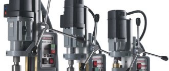
If you need to outfit your desktop CNC machine with a suitable spindle, there are some pretty attractive options available now. It's up to you to choose the device.
Hand engravers. Such a device costs from 500 rubles. It doesn’t have any particularly strong qualities, but if you have to carry out repairs or milling of soft materials with small cutters, then this unit is quite suitable for equipping a machine with a vertical spindle. Disadvantages are low rotation speed and low power. Drills. They operate very quietly and are equipped with a reliable chuck lock. At low engine speeds, the torque remains almost unchanged. This provides a significant superiority of the device over the engraver. Spindle from DC motors. With a power of 0.4 kW they provide a torque of 12,000 rpm. It is convenient to carry out various repairs and milling work with such a spindle, since it provides weak runout and the unit operates quietly. Plus the collet is made to a widely used standard. But there are disadvantages - insignificant power indicators, strong heating, which forces you to look for effective cooling
To operate, the device will require a separate power source, for which it is also important to be prepared.
When choosing a spindle, focus on its quality and compliance with the machine on which you are going to use this element.
About the advantages of spindles
A homemade design involves the use of a machine with an inclined spindle.
List of advantages:
- Equipping the machine with inexpensive clamping devices.
- Manufacturing diagrams are easy to find on Internet resources.
- Simplicity of the design solution.
- Additional equipment with any elements of the corresponding parameters.
If you are not sure that a self-made metal spindle for CNC or wood will not work effectively, then to avoid the risk, you can purchase a factory-made product.
Device
The spindle is a steel shaft, in front of which there is a mount for the working tool. In the classic style, the spindle is mounted on high-precision rolling bearings. To ensure the required accuracy of operation during operation, a special ring is installed on the spindle support. The ring is adjusted using an adjusting nut, which, when tightened, moves the nut along the spindle, which ensures the elimination of gaps formed during operation.
The design of the spindle depends on many factors, usually on the application, the type and design of the machine, the size and speed of operation. Previously, the basis of this unit was bearings, the deviation on which reached 1 micron. Today, the requirements for spindles have increased, so modern samples are made using magnetic or air supports. This solution makes it possible to achieve a minimum deviation not exceeding 0.2 microns.
For higher precision, at which the processing error is below 0.03 µm, a special drive method is used. The spindle is driven and accelerated by the flywheel, but the work is performed after the flywheel is turned off and the spindle operates due to inertia.
The design of the unit must meet the following requirements:
- Accuracy. It is selected based on the machine model, the material being processed and technological requirements.
- Speed. Different types of spindles rotate at different speeds, the faster the speed of processing the workpiece, the higher the quality of the work performed.
- Rigidity. It is determined by the ratio of the spindle deflection and the level of radial runout. The lower this indicator, the higher the quality of work.
- Durability. The service life of the unit primarily depends on the quality of the bearing used.
- Vibration resistance. The spindle must be vibration tolerant to the external vibration of the machine, which ensures high precision of the tool.
- Permissible heating. It is determined by the maximum heating temperature of the unit at which the operating characteristics of the spindle do not change.
- Load bearing capacity. Characterizes the recommended weight and dimensions of the working tool.
Typically the spindle is not considered as a separate structure. Most often, the entire complex of a screw-cutting lathe is considered, including an electric motor, drive, headstock and spindle. The electric motor can be changed, even power plants operating on direct current can be used. The main thing is that all components correspond to the electrical circuit of the machine.
Technical specifications
The device in question has an unlimited number of properties. The main technical specifications of a machine for milling work on metal include the following points:
- Power. In most cases, the power parameter is related to the parameters of the supplied electric motor. The criterion is measured in W and can vary over a fairly wide range. The choice of power takes place in accordance with the area of use of the machine.
- Rotational speed. The spindle of a milling machine can rotate at different speeds. At the same time, the newest models are distinguished by the fact that they can change the speed in steps or slowly.
The spindle milling machine is also classified according to the area of use. Depending on the power parameter, the following models are distinguished:
- For processing polymer materials and chipboard, as well as MDF, models with a power of 800 W are suitable. They cost a relatively small amount and are usually installed in a workshop at home.
- Wood, soft multi-colored alloys, textolite have a very high degree of workability. This is actually why the recommended power of the machine is 1500 W.
- Common steels, stone and hard alloys can be machined at 3000 Watts. This is quite enough for the cutter to cut into materials with very high hardness.
It must be remembered that too much power is not always considered an advantage of the equipment. This is due to the high energy consumption coefficient and price
When selecting, attention is often paid to the stepwise adjustment process.
Different designs of milling machines also determine the following characteristics:
- The efficiency criterion reaches up to 95%. Thanks to this, energy costs are significantly reduced and the efficiency of using machines is increased.
- High strength and reliability. If made well, the device will most likely last for a very long period.
- Design features make it possible to use the equipment for a long period without stopping. This is due to the presence of a cooling system.
In most cases, the operating characteristics of a spindle depend on the area of use and the required processing accuracy. In addition, a very high degree of machinability is ensured by cooling.
What parts does the system consist of and what are the main options on the market?
First, you should understand the main features of the device and only then understand the types of structures. In fact, despite all the apparent complexity, the system is easy to use, and you can master it in a matter of days.
Device
If we consider the usual options, their main components will be the following elements:
- Bed – all components are placed and secured on it; this element is most often made massive in order to reduce vibration, ensure reliability and stability during operation. As for some options, this element may not be present in them; we are talking about tabletop devices and hand-held milling cutters;
- The work table is designed for arranging workpieces during their processing, everything is quite simple: the surface must be durable, and its area must ensure the normal arrangement of the elements being processed;
- To increase convenience, clamps are most often located on the table - for a wood milling machine, their presence is mandatory for the reason that to ensure processing accuracy, each element must be fixed as reliably and firmly as possible. If you are processing the ends, then you need a stop ruler, so you can carry out the operation very accurately and evenly;
Clamps can have different configurations depending on the nature of the work performed
- The shaft for a wood milling machine performs the function of transmitting force from the power unit to the working element; it is also often called the spindle shaft; it is located on the support. This unit allows not only to transmit force and clearly fix the element, but also to adjust the position of the working element relative to the surface of the work table, depending on the characteristics of the work being carried out;
- The spindle for a wood milling machine is used to fasten working elements and is located on the drive shaft, the main requirement for it is reliability of fixation and ease of use;
The spindle must ensure quick change of working units
To make grooves on materials, remove ends in a certain shape and do other work, special cutters for a wood milling machine are used; there are a huge number of standard sizes and configurations on the market, so you can choose the best option for any type of product;
This option, such as wood cutters for machine tools, is used for work on giving the ends a certain configuration for fastening and connecting elements
Types of equipment
There are currently several main options on the market:
- CNC machines are the most high-tech option; their distinctive feature is the presence of a processor that allows you to process information and work according to predetermined parameters. This ensures the highest processing accuracy and a minimum of flaws, because you don’t have to do everything yourself, the whole process is controlled by a computer;
- Horizontal equipment has a work table and, accordingly, processes workpieces in a horizontal plane. In vertical installations, the working unit is located in a vertical plane and can move up and down, which simplifies the processing of some elements;
- Manual milling machines can hardly be called machines, but they are affordable and can handle most small jobs. In addition, with their help, you can build a small stationary device; in this case, the diagram of a wood milling machine will be a structure for attaching the tool, which may also have a copier to make products according to the sample;
In this case, you don’t even need a drawing of a wood milling machine with your own hands - you need to make a system for fastening the equipment and think about fixing the workpieces
Desktop options are most often intended for domestic needs and are good solutions for reasonable money.
Each wood cutter for the machine has its own configuration, it is advisable to have on hand a whole set with the most popular options
Basic device parameters
All equipment of this type is divided not only by design, but also by a number of indicators that should be taken into account both when choosing a ready-made option and when assembling the system yourself. The most important factors are the following:
| Power | The engine for a wood milling machine must provide the necessary performance for a particular type of work. Naturally, it is better when there is a certain reserve of power, but if you constantly perform simple work that does not require large energy costs, then an overly efficient motor will cause constant excessive consumption of electricity |
| Construction type | We'll look at the main options below, and you'll need to choose the type of layout that best suits your needs and needs. It is important to clearly understand what work you will be doing, so that later it does not turn out that another adaptation option is needed |
| Equipment quality | In no case should price be the main criterion when choosing; in addition to low quality, such options are also characterized by low performance indicators. The service life of cheap samples is short, and often if they break down, it can be very, very difficult to find the necessary spare parts for wood milling machines of unknown origin. |
| Availability of necessary communications | If you want to carry out certain work on an ongoing basis, then you need to make sure that you have a room with sufficient space at your disposal, and you also need to make a dust removal system. An important factor is the operating voltage of the machine; if it is 380 Volts, and you do not have an appropriate line, then the cost of supplying it may be more expensive than the equipment itself |
Important! Among other things, a number of other factors should be taken into account: the equipment included, its warranty, the availability of documentation confirming quality, and instruction manuals in Russian.
Industrial portal-type CNC equipment allows you to perform almost any wood processing work
Spindles for CNC machine
- How to choose a spindle drive?
- Selecting the spindle cooling type
- Selecting spindle speed and power
Application of brushless spindles
The need for high-speed machining led engineers to the invention of brushless spindles. Spindles based on electric brushless (BLDC) motor are used for engraving, milling and drilling of various materials. The design of such spindles is based on a rotor with permanent magnets and a stator with windings.
Operating principle of brushless spindles
Most often, brushless spindles operate on the basis of a three-phase motor. The operating principle of brushless spindles on such a motor is simple: a squirrel-cage rotor with its own magnetic field is placed in the running magnetic field of a three-phase stator. The rotor begins to rotate due to the interaction of its magnetic field and the stator field, at a slightly lower speed. This spindle design allows materials to be processed at high speeds, and this is due to the following factors:
- reduced rotor weight
, achieved by using lightweight materials with pronounced magnetic properties, allows the spindle to produce a higher number of revolutions per minute; - The elongated cylindrical shape of the spindle
allows the most efficient use of the device’s performance and increases its efficiency with the compact size of the device. Thanks to this, the modern brushless spindle has compact dimensions with low power consumption. Such a spindle would be very suitable for use in a desktop CNC machine for metal when processing steel, cast iron, wood, plastic, and precious metals. stones and other very different materials.
Brushless spindle speed control
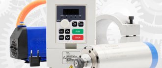
The speed of the brushless spindle is adjusted by frequency conversion of 3-phase current and voltage. For this purpose, frequency converters are used, which are always used with asynchronous motors. Important reminder: the power of the spindle and the frequency converter must match.
Prices for brushless spindles vary significantly in the machine tool market. DARXTON offers to buy a brushless spindle at a reasonable price. If you have any questions, please contact our specialists by mail
CNC spindle clamping devices
Milling spindles of CNC woodworking machines for the production of MDF facades, depending on the design of the tool clamping device, can be divided into two groups:
- Spindles with manual tool change;
- Spindles with automatic tool change.
At the end of the spindle shaft with manual tool change there is an internal cone and an external thread onto which a tool nut with a collet is screwed. The most common collet clamp device in the woodworking industry is the ER standard. In CNC machines intended for furniture production, as a rule, spindles with an ER32 collet clamp are used to fix tools with a cylindrical shank with a diameter of 2 to 20 mm.
Milling spindles with automatic tool change have a more complex design. At the end of the shaft there is a gripping mechanism, and inside the same shaft there is a retaining spring with a rod and a pneumatic cylinder. In the passive state, the chuck (mandrel) with the tool is securely held by the force of the spring. When high pressure air is supplied, the spindle pneumatic cylinder presses on the rod, which in turn weakens the gripping elements.
Today, on CNC machines and machining centers for processing wood materials with automatic tool changing, two quick-release chuck standards have become most popular: ISO and HSK. The ISO type spindle tooling system chuck is shaped like a cone. Its main advantage is working with massive tools at low or medium speeds.
The HSK standard quick release chuck has a hollow conical shank. Its design is rigid and lightweight. It was designed specifically for high speed and high precision machining.
Bearing adjustment
No matter how good the technique was initially, over time it loses its positive qualities. Problems with bearings are inevitable during long-term operation. Even earlier they appear due to overloads and vibrations. Ignoring this point risks not only poor processing quality, but also equipment damage. You can adjust the bearings (or rather, their clearances) on cantilever milling cutters using approximately the same scheme:
- introduction of the mandrel;
- touching the cylindrical protrusion with an indicator pin;
- swinging the spindle with a mandrel in the support;
- marking the largest deviations of the indicator (they should be no more than 8-10);
- if exceeded, adjust according to the instructions.
Selecting the type of cooling
Cooling of the rotation zone is required to increase service life. There are two types.
Water (liquid)
Differences:
- They are very quiet - the liquid flows almost silently. But at the same time there is another loud sound from the movement of the impeller.
- The presence of a circuit that includes a system of tubes, a container, and a pump. It is necessary to constantly monitor the moisture supply and its temperature.
- Can operate at low speeds.
Air
Distinctive features:
- Strong and not the most pleasant sound.
- Chips may fly away under the influence of a jet of air.
- It is necessary to clean the shirt where metal particles become clogged at regular intervals.
- It is required to monitor the temperature very carefully; ideally, install a sensor with a signal, because the entire device is very sensitive to overheating.
As a result, we recommend using the air option when working with soft materials, but when the workpiece is made of durable metal, it is better to use liquid cooling.
Technical characteristics of the lathe 16K20
| Parameter name | 16K20 | 16K20P |
| Basic machine parameters | ||
| Accuracy class according to GOST 8-82 | N | P |
| The largest diameter of the workpiece installed above the bed, mm | 400 | 400 |
| Height of the center axis above the flat guides of the frame, mm | 215 | 215 |
| The largest diameter of the workpiece processed above the support, mm | 220 | 220 |
| Maximum length of the workpiece installed in the centers (RMC), mm | 710, 1000, 1400, 2000 | 710, 1000 |
| The greatest distance from the axis of the centers to the edge of the tool holder, mm | 225 | 225 |
| The largest diameter of the drill when drilling steel parts, mm | 25 | 25 |
| Maximum mass of workpiece processed in centers, kg | 460..1300 | 460..1300 |
| Maximum mass of workpiece processed in the chuck, kg | 200 | 200 |
| Spindle | ||
| Spindle hole diameter, mm | 52 | 52 |
| The largest diameter of the rod passing through the hole in the spindle, mm | 50 | 50 |
| Spindle rotation speed in forward direction, rpm | 12,5..1600 | 12,5..1600 |
| Spindle rotation speed in reverse direction, rpm | 19..1900 | 19..1900 |
| Number of forward spindle speeds | 22 | 22 |
| Number of spindle reverse speeds | 11 | 11 |
| Spindle end according to GOST 12593-72 | 6K | 6K |
| Tapered spindle bore according to GOST 2847-67 | Morse 6 | Morse 6 |
| Spindle flange diameter, mm | 170 | 170 |
| Maximum torque on the spindle, Nm | 1000 | 1000 |
| Caliper. Submissions | ||
| Maximum length of longitudinal movement, mm | 645, 935, 1335, 1935 | 645, 935 |
| Maximum length of transverse movement, mm | 300 | 300 |
| Speed of fast longitudinal movements, mm/min | 3800 | 3800 |
| Speed of fast transverse movements, mm/min | 1900 | 1900 |
| Maximum permissible speed of movement when working on stops, mm/min | 250 | 250 |
| Minimum permissible speed of movement of the carriage (support), mm/min | 10 | 10 |
| Price for dividing the longitudinal movement dial, mm | 1 | 1 |
| Transverse movement dial division price, mm | 0,05 | 0,05 |
| Longitudinal feed range, mm/rev | 0,05..2,8 | 0,05..2,8 |
| Transverse feed range, mm/rev | 0,025..1,4 | 0,025..1,4 |
| Number of longitudinal feeds | 42 | 42 |
| Number of cross feeds | 42 | 42 |
| Number of threads to be cut - metric | ||
| Number of threads to be cut - modular | ||
| Number of threads cut - inch | ||
| Number of threads to be cut - pitch | ||
| Limits of metric thread pitches, mm | 0,5..112 | 0,5..112 |
| Limits of pitches of inch threads, threads/inch | 56..0,5 | 56..0,5 |
| Limits of modular thread pitches, module | 0,5..112 | 0,5..112 |
| Limits of pitch thread pitches, diametric pitch | 56..0,5 | 56..0,5 |
| The greatest force allowed by the feed mechanism on the cutter is longitudinal, N | 5884 | 5884 |
| The greatest force allowed by the feed mechanism on the cutter is transverse, N | 3530 | 3530 |
| Cutting slide | ||
| Maximum movement of the cutting slide, mm | 150 | 150 |
| Movement of the cutting slide by one division of the dial, mm | 0,05 | 0,05 |
| Maximum angle of rotation of the cutting slide, degrees | ±90° | ±90° |
| Scale division of the tool slide rotation scale, deg | 1° | 1° |
| The largest cross-section of the cutter holder, mm | 25 x 25 | 25 x 25 |
| Height from the supporting surface of the cutter to the axis of the centers (cutter height), mm | 25 | 25 |
| Number of cutters in the cutting head | 4 | 4 |
| Tailstock | ||
| Tailstock quill diameter, mm | ||
| Cone of the hole in the tailstock quill according to GOST 2847-67 | Morse 5 | Morse 5 |
| Maximum movement of the quill, mm | 150 | 150 |
| Movement of the quill by one division of the dial, mm | 0,1 | 0,1 |
| The amount of lateral displacement of the headstock body, mm | ±15 | ±15 |
| Electrical equipment | ||
| Main drive electric motor, kW | 11 | 11 |
| Electric motor for fast movement drive, kW | 0,12 | 0,12 |
| Coolant pump electric motor, kW | 0,125 | 0,125 |
| Dimensions and weight of the machine | ||
| Machine dimensions (length width height) RMC=1000, mm | 2795 x 1190 x 1500 | 2795 x 1190 x 1500 |
| Machine weight, kg | 3010 | 3010 |
Design and technical features
Knowing the structure of a milling machine, a person immediately understands what a spindle is and where it is located. For those who do not know the design and technical parameters, it is necessary to understand everything gradually.
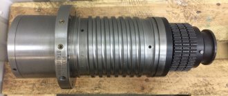
The spindle is a hollow metal shaft that is the key component in a milling machine. This part is installed on a special carriage, with the help of which it moves in three planes - X, Y, Z. When the engine is turned on, the shaft directly transmits rotational force to the cutter (if we are talking about a machine that uses metal cutters). Due to the absence of additional elements when transmitting force from the engine, the torque is not distorted.
Spindle for a homemade machine. Spindle machine for wood.
Cooling methods
Cooling of conventional electric motors is organized by blowing the fins on the housing with a fan mounted on the motor shaft. It is more difficult to organize cooling in a closed spindle housing. This can be solved in two ways - by forced blowing through ventilation grilles and channels inside the case or by using water cooling.
Water cooling is more common on industrial machines. Requires additional devices and pipelines, but cools the system much more efficiently than air.
Shafts and spindles, their purpose and application
Shafts
They are the main components of machine tools and are intended to transmit rotation from the electric motor to the actuators. All shaft operation is associated with long-term load conditions:
- bending;
- compressive;
- torque;
- stretching;
Shafts with splines facilitate easy movement of gears in the longitudinal plane. Shafts with increased loads, to reduce their weight and overall dimensions, are produced with cavities inside.
Hollow types of shafts are made through which it is structurally necessary to pass parts with assemblies. These are the chucks of lathes, milling machines and many other metal-cutting machines. Parts with assemblies are secured to them using splined or keyed connections.
Protrusions and grooves
on the body serve as clamps to hold the shaft from axial movement. Retaining rings that fit over the grooves are also used. Most spindles only rotate in their bearings. These are the working units of the machines:
- cartridges for metal-cutting machines;
- chassis rollers;
- working shafts in gearboxes and feeds of machine tools.
In addition to rotation, chucks in machines for drilling, boring and some other equipment simultaneously perform translational motion. Honing machines and their spindles also operate simultaneously in a reciprocating mode.
Machine shaft diagrams
Spindles and shafts
metal cutting machines,
In addition to strength characteristics, they must meet a number of other requirements:
- 1. Sufficient degree of rigidity. If the rigidity is weak, the shaft bends too much, which leads to bearing failure. This also leads to disruption of the smooth engagement of gears mounted on the shafts with each other.
- 2. Connection accuracy. GOST regulates an increased degree of accuracy at the points where gears are installed on shafts and under journals where bearings are pressed.
- 3. High degree of wear resistance. Working journals in metal-cutting equipment, which rotate in plain bearings, have high wear resistance. Increased requirements for wear resistance are imposed in places of repeated linear movement of shafts and spindles or parts and gears installed on them. The cartridges of all metal-cutting machines and other mechanisms are subject to this process.
- 4. Resistance of shafts and spindles to vibration. Machines with high cutting speeds that perform metal finishing operations must have high resistance to vibration load conditions.
All mentioned conditions are satisfied by the unconditional use of only modern innovative materials of European quality for the manufacture of spindles and shafts. It is imperative to carefully follow the rules of heat treatment, grinding, fitting components and parts, high-quality assembly and adjustment of the entire machine as a whole.
Machine spindle designs:
a – drilling; b – boring; c – milling; g – revolver; d – turning; e – grinding
Spindle and chuck
metal-cutting machine are carried out strictly in accordance with GOST. This is done to make it easier to secure fixtures or tools in the spindle jaws. The spindles operating in rolling bearings are made from steel 45 and 40X with hardening and tempering to HB 230-260.
The industry produces spindles that operate in sliding bearings from 20X steel, followed by carburization to a layer depth of 0.8-1.0 mm, hardening and tempering to 56-62.
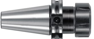
Design Features
The milling machine spindle is a high-tech device assembled in a temperature-controlled room using high-precision and high-speed bearings. The end of the spindle is bored and ground to a taper (ISO, BT, SK, HSK, Morse, etc.). This is necessary for a tight fit of the milling mandrel and accurate installation of the cutter. The fixation of the mandrel with the cutting tool is carried out using external force, most often with a set of disc springs.
The spindle consists of several components - a stationary body, a rotating part, bearings, a coolant system, pulleys, balancing rings, etc. The role of a stationary body on low-speed spindles can be performed by the spindle headstock.
Also in technical language there is a substitution of concepts: spindle as an assembled device and spindle as a rotating part of the spindle assembly.
The spindle rotates in supports. The role of supports is performed by high-precision bearings, the diameter and type of which depend on the size range of the spindle. Milling machines do not use spindles on hydrostatic bearings, because... cutting force and minimum deviation from the axis of rotation are not provided
Classification
Technical characteristics, diagrams and operation of the 6р12 milling machine
Given the variety of milling machines and spindles, it is easier to classify them according to their technical characteristics:
- Rotary type milling spindle. Often made independently.
- Vertical rotary mechanisms.
- Equipment with two spindles.
- Mechanisms used when working with end parts.
- Vertical rotating structures for manual processing.
If we talk about using spindles at home, we can highlight engravers. They are often installed on homemade milling machines. However, these machines have a serious drawback. Due to the weak torque, the metal is processed with great difficulty. Most often, wood or plastic is processed with such equipment.
Bormashinka
Often these devices are compared to engravers. The main difference is the preservation of torque regardless of changes in speed. The drills are also equipped with a cartridge clamp and are quieter than engravers.
DC motor
A special mechanism that is equipped with CNC. It works quietly and does not create vibrations. Thanks to the presence of CNC, it becomes possible to change the power during operation. The key disadvantage of a DC motor is a poor cooling system, and as a result, rapid overheating when working with hard materials. To avoid damaging metal workpieces and damaging the engine, additional cooling is required.
DC motor
Straight grinder
Often this equipment is used as a milling spindle. It can be used to process both wood and metal. The kit does not include a device for adjusting power, which reduces the functionality of the straight grinder. It also makes loud noises when working with metal.
Sparky milling cutter
Used as a rotary milling spindle. The advantages of this equipment are high power, high productivity and the ability to regulate speed. Sparky milling cutters also have good cooling, which prevents the processed materials from overheating. Used for working with wood and metal.
Kress milling cutter
Excellent price/quality ratio. Can be equipped with CNC systems. High performance, ability to regulate speed. It is possible to work with various materials.
Criterias of choice
Choosing a milling machine begins with an analysis of the material it will have to work with: metal or wood.
Then technological operations and the scope of work are analyzed. When choosing a spindle, pay attention to its main characteristics:
- rotation frequency;
- power;
- design;
- speed adjustment;
- method of attaching the tool;
- work performed;
- type of cooling.
It is worth paying attention to the current connected to the equipment
Power
The choice of spindle power is determined by the hardness of the material being processed. For wood and boards made from its waste - chipboard, MDF, a power of up to 3 kW is sufficient. The equipment can process plastic, plywood, and do engraving.
Non-ferrous metals and their alloys are relatively soft, but have a high viscosity coefficient. A clean cut is obtained only with a power of up to 6 kW and a rotation speed of 18,000 rpm. Machining steel and cast iron requires a spindle with a power of more than 6 kW and a rotation speed of up to 22,000 rpm. Depending on the hardness and viscosity of the material, the modes are selected by a combination of rotation speed and feed rate.
Milling method
Milling is done in a counter and reverse manner. The rotation of the tool is directed against the movement of the part or coincides with it.
There are processing modes:
- power;
- express
In the power mode, processing occurs with a large feed, at low speeds, due to the power of the spindle. The cutting edge captures a thick layer of material every time. The high-speed mode assumes the ability of the tool to rotate at high speed. The table service is small. The mode is suitable for non-ferrous metals and wood and guarantees high cleanliness of the treated surface.
Important! Cast iron can be processed well at low speeds and low feed rates. He doesn't like high speeds.
Cooling
Milling spindles have 2 types of cooling:
- air;
- water
For cooling by air flows, special slots are made in the unit body. When the shaft rotates, turbulence occurs and cold air is drawn in from outside. The water cooling system is complex in design. It must be sealed. Air-cooled spindles installed on home equipment last longer.
On industrial equipment, bearings reduce friction and heating of the spindle. Enough air flow. The gearbox is lubricated and cooled with oil. The engine has its own cooling system - an impeller on a shaft.
Workpiece material
Cutting modes and sharpening angle of the cutting edge are selected according to the characteristics of the workpiece material.
Tree
A clean cut is obtained when processing wood with a rapidly rotating tool. Feed and cutting depth are small. The spindle is suitable for high-speed, with a power of up to 1.5 kW.
Important! When processing wood in a power mode, chips and cracks between the fibers form on the part, and the surface becomes rough.
Metal
Cutting metal requires a lot of power and high strength of the unit. During machining of a part, in addition to the torque, resistance acts on the spindle. Its force is directed perpendicular to the axis of rotation.
Metal spindles have a durable, massive body, mostly cast iron. The shaft is equipped with thrust and radial bearings. The rotation speed of the tool should be adjusted between 20–18,000 rpm.