GOST 18877-73 Group G23
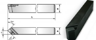
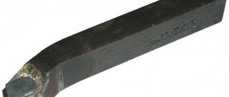
INTERSTATE STANDARD TURN-BENT LATHE CUTS WITH CARBIDE ALLOY PLATES Design and dimensions Carbide-tipped bent bull-nose turning tools. Design and dimensions
ISS 25.100.10
Date of introduction 1974-07-01
ENTERED INTO EFFECT by Resolution of the State Committee of Standards of the Council of Ministers of the USSR dated June 8, 1973 N 1429 The validity period was removed by Decree of the State Standard of the USSR dated 02.20.81 N 866 INSTEAD OF GOST 6743-61 in terms of type 1; MN 575-64; MN 576-64; MN 5199-64 EDITION with Amendments No. 1, 2, approved in February 1981, November 1984 (IUS 5-81, 2-85), Amendments (IUS 6-88, IUS 4-89)
1. This standard applies to general purpose turning bent cutters with corners , , and soldered carbide plates. The standard fully complies with ST SEV 191-75.
2. The design and main dimensions of the cutters must correspond to those indicated in the drawing and table.
Damn.1
________________
*Dimensions for reference.
Dimensions in mm
| Incisors | |||||||||||
| With insert angle 10° | With insert angle 0° | Tool holder | Type of plates according to GOST 25395-90 | ||||||||
| rights | left | rights | left | for mortise angle | |||||||
| Designation | Applicability | Designation | Applicability | Designation | Applicability | Designation | Applicability | ||||
| 2102-1097 | 2102-1098 | 2102-1099 | 2102-1101 | 10x10 | |||||||
| 2102-1102 | 2102-1103 | 2102-1104 | 2102-1105 | 12x12 | |||||||
| 2102-0021 | 2102-0022 | 2102-0071 | 2102-0072 | 16x10 | |||||||
| 2102-0023 | 2102-0024 | 2102-0073 | 2102-0074 | 16x12 | |||||||
| 2102-1106 | 2102-1107 | 2102-1108 | 2102-1109 | 16x16 | |||||||
| 2102-0025 | 2102-0026 | 2102-0075 | 2102-0076 | 20x12 | |||||||
| 2102-0027 | 2102-0028 | 2102-0077 | 2102-0078 | 20x16 | |||||||
| 2102-1111 | 2102-1112 | 2102-1113 | 2102-1114 | 20x20 | |||||||
| 2102-0005 | 2102-0006 | 2102-0055 | 2102-0056 | 25x16 | |||||||
| 2102-0029 | 2102-0030 | 2102-0079 | 2102-0080 | 25x20 | |||||||
| 2102-1115 | 2102-1116 | 2102-1117 | 2102-1118 | 25x25 | |||||||
| 2102-0009 | 2102-0010 | 2102-0059 | 2102-0060 | 32x20 | |||||||
| 2102-0031 | 2102-0032 | 2102-0081 | 2102-0082 | 32x25 | |||||||
| 2102-1119 | 2102-1121 | 2102-1122 | 2102-1123 | 32x32 | |||||||
| 2102-0013 | 2102-0014 | 2102-0063 | 2102-0064 | 40x25 | |||||||
| 2102-0033 | 2102-0034 | 2102-0083 | 2102-0084 | 40x32 | |||||||
| 2102-1124 | 2102-1125 | 2102-1126 | 2102-1127 | 40x40 | |||||||
| 2102-0017 | 2102-0018 | 2102-0067 | 2102-0068 | 50x32 | |||||||
| 2102-0035 | 2102-0036 | 2102-0085 | 2102-0086 | 50x40 | |||||||
| 2102-1128 | 2102-1129 | 2102-1131 | 2102-1132 | 50x50 | |||||||
An example of a symbol for a right-hand cutter with a cross-section of mm, with an angle of insertion of the plate into the rod of 0°, with a plate made of hard alloy grade T15K6:
Cutter 2102-0055 T15 K6 GOST 18877-73
1, 2. (Changed edition, Amendment No. 1, 2).
3. The insertion angle of the plate into the rod for processing cast iron and other brittle materials is 10°, for processing steel and other viscous materials - 0°. (Changed edition, Amendment No. 2).
4. (Deleted, Amendment No. 1).
5. Structural elements and geometric parameters of the cutters are indicated in Appendix 1.
6. The form of sharpening the front surface and finishing of the cutting part are indicated in Appendix 2.
7. Technical requirements - according to GOST 5688-61.
8. (Deleted, Amendment No. 2).
Purpose and scope of application
Turning cutters belong to the main type of tools in metal and woodworking installations operating at high speed, including CNC, GPS, GPM (even on manually operated lathes).
The blanks acquire the required shape and size in contact with the part. They are classified according to the type of processing, method of attachment, direction of feeding movement, purpose.
Compared to solid versions, a replaceable insert located on the cutting edge must be replaced in case of wear or the need for another type of work. This allows you to significantly speed up the production process and expand the range of interaction with work surfaces.
The following operations are carried out using carbide elements:
- surface treatment of the workpiece;
- thread cutting;
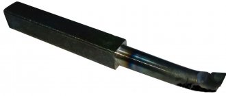
- boring the inner surface;
- scan;
- cutting glass, getinaks, non-ferrous metal;
- selection of grooves, recesses, grooves.
Plan angles
For a cutting tool, they have the following names of plan angles:
- main angle;
- auxiliary;
- corner located at the apex.
The first is formed between the plane of the edge projection and the main plane of the tool.
The second is determined between the continuation of the projection of the cutting edge with a plane directed along the movement of the workpiece.
Cutter angles in plan
The third is between the first listed plane and the main plane.
The numerical values of the parameter located at the vertex can take positive and negative values. It turns out positive when the top of the sharpening point is at the lowest point of the workpiece. Minus sign - the peak reaches its highest point.
Design
A turning cutter consists of two structural parts: a holder, with the help of which the tool fits into the mounting groove of the machine, and a cutting head. The holder is made in a rectangular or square shape and is the main part of the device.
The head consists of an edge sharpened at the required angle and several planes; it is the working part of the device; during processing it gives the workpiece the required shape. The sharpening angle affects how the cutter removes metal from the workpiece.
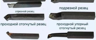
By design, cutters are divided into several types:
- straight: the holder and the working head are located on one axis, or on two parallel ones;
- curved: when viewed from the side, a curved holder is visible;
- bent: viewing the tool from above, the bend of the working part is clearly visible;
- drawn: the width of the holder is greater than the working head, drawn to the left or right. The axes of both parts of the part coincide or are shifted.
When sharpening is required
There are two cases in which it is necessary:
- the edge has worn out and lost its useful qualities;
- a new tool is released.
In both cases, it must be carried out, otherwise you simply will not be able to process the part with the required accuracy and ensure the required surface quality. Plus, during the process, the workpiece will probably additionally suffer from beating and vibration.
So be sure to do it when it is required, that is, regularly and in a timely manner; Thus, you will provide the blade with the necessary sharpness and reliability, which will have a positive impact on the overall level of safety of technological operations on the machine.
Rules for sharpening
- use only a suitable abrasive wheel;
- work with gloves and a mask (goggles), do not forget about protection;
- clean all the main parts and elements of the turning cutter from dust and dirt and fix it in the tool rest, adjusting the position;
- first of all, remove the rear corners and only after measuring and checking them, proceed to the front ones;
- do not neglect fine-tuning - it is needed in every area where even the smallest irregularities are observed.
Tools used
The base in this case is a pair of grinding wheels: one is made of green silicon carbide, the other is made of electrocorundum. The first is suitable for materials with a high degree of hardness, the second for softer tool steels.
You will also need a grinding machine for finishing operations. Since the latter are considered thin, the equipment must operate at low speeds with the lowest possible level of runout. A diamond or CBN surface is suitable as an abrasive.
Advantages and disadvantages
Cutters with replaceable inserts have the following advantages:
- quick replacement of the main part of the part;
- Compliance with most machines and devices;
- the ability to quickly change cutting elements;
- wear resistance, high degree of reliability at high speeds;
- low price of components;
- commonality of cutting elements;
- increasing the service life of the cutter holder due to the use of removable elements made of hard alloys.
Among the shortcomings noted:
- high cost of imported parts compared to domestic ones;
- Incorrect fastening of the plate leads to damage to the tool and reduces its service life.
Making your own cutters: a step-by-step guide
The main thing is to use only tool steel that has sufficiently high performance characteristics.
Selecting the required configuration of files or rasps
The selection of these parts will be easier if the owner knows in advance exactly what tasks he faces. After this, choosing the length, shape and size will not be difficult. Here are some tips.
- If you need to file up to 5-10 mm in thickness, it is better to stop at cut number 0 or 1.
- The processing accuracy should be within 0.01-0.02 mm.
- It is much easier to choose devices based on length.
The main guideline is the dimensions of the surface that needs to be sawed. The larger this parameter, the larger the device itself should be.
You can use a specific formula to make the calculation more accurate. We add 15 cm to the length of the surface of the product. We get the value, which will be the length of the working surface of the file or rasp. The main thing is that when working, the tool is passed over the entire workpiece.
Fastening cutting parts
Homemade tools do the same as professional ones. The optimal solution is self-tapping screws. The higher quality the product, the better.
Only regular sharpening of the cutters will allow you to obtain the most accurate results. The need for the procedure arises not only for instruments that have disposable carbide inserts. The work is performed by specialized machines when it comes to large-scale manufacturing enterprises.
There are practically no restrictions on the method for home use. Suitable for use with conventional sharpening wheels and chemically active reagents. Machines for universal, specialized purposes are a cheap option that maintains efficiency.
When processing the back of a tool, there are three main stages.
- Maintaining the same angle as the holder itself at the back. The increase in the indicator compared to the rear cutting angle is 5 degrees.
- The second stage involves processing the surface of the cutting insert itself from the back. Here we need to keep the excess equal to 2 degrees.
- Finishing is the third stage. It is needed to form the required rear angle.
The front surface also goes through several processing stages.
Refinement and polishing
This is done with carbide on a special cast iron disk. The device rotates, maintaining a speed of up to 1-2 m/s. The direction of rotation of the disk itself is towards the working edge, away from the supporting part of the tool.
Consistently grind the blades and tool surfaces. The incisors are almost brought to a shine, and any irregularities are removed.
Why is fine-tuning needed? A tool becomes dull and wears out over time if it is used often enough. The reason is that the plate rubs against the workpieces and chips. If the plate is smoother, there will be less friction. In this situation, tool wear slows down.
The finishing process has other features:
- When finishing, abrasive pastes are used, the main component of which is boron carbide.
- Finishing involves wetting the tool with kerosene.
- Then the paste is applied to the surface in a zigzag manner.
- The instrument is brought to the disk.
- GOI paste can be used in conjunction with kerosene.
- Kerosene is not a mandatory step when using modern lubricants.
It is important to install the support table correctly. After its installation, in comparison with the middle part of the disk, the cutter blades with the part are on the same lines, or lower. Rotation of the disk - towards the threaded plate, directed
The rotation of the disk is directed towards the threaded plate.
The paste particles begin to be crushed when the tool is pressed and finishing is started. The cutter has no chips or abrasions when passing through the edges. Irregularities on the incisal surface are eliminated thanks to the very grains of the paste.
Toolholder classification
Turning holders are divided into several types, depending on the type of fixation.
ISO C mounting system
Classic connection system “Clamp from above” for plates without holes. Used for external and internal roughing, end trimming, turning along the workpiece. When using, the structure of the chipbreaker is taken into account. Provides rigid fixation of the part and good cycle repeatability.
ISO D system for metal cutting machine
Double clamping of the bracket guarantees strong fixation of the plate and reliable positioning in the cutter. Used for inserts with a hole for cutting large amounts of chips.
Recommended for roughing, finishing, and finishing operations on large diameter holes. Ensures unhindered chip flow and quick insert replacement. Suitable for fastening ceramic and carbide parts.
ISO M fastening system cutter
Indicates pressing from above and pressing behind the hole. Allows single-sided plates to be secured without back corners. Provides reliable, rigid clamping with simultaneous pressure on the plate and the inside of the socket.
ISO S system
Screw fastening is used primarily for fixing small-sized tools when boring small-diameter holes. And also for external processing of parts of reduced rigidity.
The most compact, reliable fastening system, ensuring free flow of chips, does not require a large number of components (compared to the old type of fixation with a top clamp).
Selection criteria
Despite the fact that turning cutters are considered consumable elements of a lathe, their choice, like the choice of any other tool, should be approached responsibly. A correctly selected turning tool will allow longer operation and better processing of products. First of all, it is worth considering what work will be performed.
If the range of work is quite wide and includes processing different types of parts, then it is worth stocking up on not just one type of cutter, but several at once. It is preferable to purchase a set of cutters. This way you will be as calm as possible in the event that you do not have the cutter you need on hand.
Also, you should take into account the size of the workpiece being processed. The choice of cutter size also depends on the size of the workpiece. Most often, a medium-sized incisor is purchased. They are more versatile and allow you to work with various products without requiring replacement.
Another selection criterion should be the material used to make the tool. When the workpiece is made of soft and unhardened metal, cutters are chosen, the material for which is high-speed steel.
In cases where processing will take place on hard materials, I use cutters made of carbide materials. Such cutters are resistant to vibration vibrations and temperature changes, and their service life is much longer.
Mechanical mount selection
When choosing a turning tool, the following factors are taken into account in order to optimize production.
- The shape, dimensions of the part, as well as the cleanliness of processing, its accuracy, indicating the direction of movement of the tool, the sequence of the process.
- The type of operation that influences the choice of cutting part: part cutting, threading, turning, grooving, etc.
- The structure of the cutting plate, the amount of input, and the speed of rotation of the part affect the accuracy and degree of surface roughness of the part.
- For external processing and boring of products, different cutters and carbide inserts are chosen.
- Rigidity of the workpiece, tool, processing conditions of the part. For example, in vibration conditions, pay attention to the size of the device, and take into account the geometry of the tool.
- The method of fixation, the dimensions of the tool fit, depending on the design, dimensions of the machine, as well as its power and technological capabilities.
- Workpiece material: cast iron, stainless, alloy or carbon steel.
- Productivity, tool efficiency, influencing the quality of processing. Batch size, equipment downtime, etc.
- Preservation of the range of tools used in production, which affects the level of optimization.
Drawing
Table 1
| Sharpening shape | |||
| Number | Front surface | Sketch | Application area |
| I | Flat, positive rake angle | Machining gray cast iron, bronze and other brittle materials | |
| II | Flat with negative bevel | Processing of malleable cast iron, steel and steel casting kgf/mm, as well as kgf/mm with insufficient rigidity of the technological system. Use a chipbreaker to remove and crush chips | |
| IIa | Flat, negative chamfer and brazed chipbreaker | Processing of steel and steel castings kgf/mm when curling and crushing chips is necessary | |
| III | Curvilinear, with negative chamfer | Processing steel kgf/mm when curling and crushing chips is necessary | |
| IlIa | Flat, with a small hole and | Processing of steel and steel castings at kgf/mm | |
| IlIb | Flat, with a small hole and | Processing of steel and steel castings at kgf/mm | |
| IV | Flat, negative rake angle | Roughing of steel and steel castings kgf/mm contaminated with non-metallic inclusions. Dealing with shocks in a harsh process system | |
| V | Curvilinear, with negative chamfer | Processing of stainless steels kgf/mm | |
| VI | Processing of materials from kgf/mm | ||
| VIa | Curvilinear, with negative chamfer | Processing of materials up to 130 kgf/mm | |
| VIb | Processing of materials up to 120 kgf/mm | ||
| VII | Flat with negative rake angle | Processing of materials with over 120 kgf/mm | |
2. Finish the front and rear surfaces along the main cutting edge and along the radius. 1, 2. (Changed edition, Amendment No. 1, 2).
3. To strengthen the tip of the cutter and better heat dissipation, it is recommended to sharpen the auxiliary plane at an angle of 15° over a length of 3 ... 5 mm.
table 2
mm
| Incisors | Head width | |||||||
| Elements of the cutting part of the incisors | until 3 | 10-12 | 15-20 | St. 20 | ||||
| Turning, planing, slotting | Cut-off, slotted | Dullness | ||||||
| Chamfer width | 0,15 | |||||||
Table 3
mm
| Incisors | Elements of the cutting part of the incisors | Section | |||||||||||||
| — | — | 16x12 | 20x16 | 25x20 | 32x25 | 40x32 | 50x40 | ||||||||
| 6x6 | 8x8 | 10x10 | 12x12 | 16×16 | 20x20 | 25x25 | 32x32 | 40x40 | 63x40 | ||||||
| — | — | 16x10 | 20×12 | 25x16 | 32x20 | 40x25 | 50x32 | 63x50 | |||||||
| 6* | 8* | 10* | 12* | 15 | 20 | ||||||||||
| Planing | Pass-through, undercut | ||||||||||||||
| Pass-through, undercut | Vertex radius | ||||||||||||||
| Boring | |||||||||||||||
| Pass-through, undercut | Chamfer width | 0,15-0,2 | 0,3-0,4 | 0,6-0,8 | 0,9-1,2 | ||||||||||
| Turning | Boring | 0,1-0,15 | 0,2-0,3 | 0,4-0,5 | |||||||||||
| Passing, scoring, boring | Point shape III | ||||||||||||||
| Sharpening shape IIIa, IIIb | 8-10 | 10-12 | 14-10** | 16-18 | 22-24 | 28-30 | |||||||||
| Passing | Sharpening form IIa | ||||||||||||||
________________
* Diameters of the drawn part of the boring cutters. ** The text corresponds to the original. — Note.
4. The geometric parameters of the cutting parts of the incisors when sharpening and finishing them with diamond wheels are indicated in Figure 2.
Metal cutting modes
The cutting mode is a set of values calculated by calculation.
- Depth , which determines the thickness of the layer to be removed in one operation. When processing the end, the depth indicator is determined by the diameter of the part; for flat parts, the length is used.
- Speed . It is calculated by multiplying the number of revolutions per minute of the part by its diameter. This takes into account the type of operation being performed, the type of tool, and the material of the workpiece.
- Submission . An indicator of the movement of the cutter per revolution of the part. After calculation, these values are compared with the standard indicators specified in the machine passport.
Also, when calculating the cutting mode, the parameters of turning equipment are taken into account:
- power, spindle speed and others.
Advantages and disadvantages
It is quite difficult to determine the pros and cons of such a product. First of all, its versatility in operation will be an undoubted advantage. With this tool you can perform many types of actions (rough and fine finishing, thread formation, trimming of various parts, and many others).
The downside of such a tool is its expense. Turning cutters are primarily consumables and during operation they often break, grind down and become unusable. Therefore, before performing any turning activities, you should stock up on tools for future use.
Equipment prices
Most often, sets consisting of cutters with plates are presented for sale. As practice shows, the use of replaceable elements significantly saves the cost of purchasing components. The cost is affected by the modification, configuration, and brand of products.
- a set of cutters and plates made in Germany costs 5,300-7,200 rubles, depending on the size;
- China offers from 283 to 710 rubles per set;
- Stalex and Jet (Switzerland) have almost the same price - about 6,400 rubles.
When choosing cutters with replaceable inserts, study the markings of the holders and pay attention to the quality and structure of the head and holder. An incorrectly selected tool will complicate the processing of parts and will negatively affect the outcome of the work performed.
Damn.1
Damn.1
Table 1
Dimensions in mm
| Cutter section | Designation of plates according to GOST 25395-90 | |||
| 10x10 | 01331 | |||
| 12x12 | 10,0 | 01352 | ||
| 16x10 | 13,0 | 01331 | ||
| 12,0 | 14,0 | 01352 | ||
| 16x12 | 12,0 | 14,0 | 01352 | |
| 16x16 | 11,0 | 13,5 | 01372 | |
| 20x12 | 16,0 | 18,0 | 01352 | |
| 15,0 | 17,5 | 01372 | ||
| 20x16 | 13,5 | 17,0 | 02252 | |
| 20x20 | 13,5 | 17,0 | 01392 | |
| 25x16 | 18,5 | 22,0 | 02252 | |
| 18,5 | 22,0 | 01392 | ||
| 25x20 | 13,2 | 18,5 | 22,0 | 02272 |
| 25x25 | 17,5 | 21,5 | 01152 | |
| 32x20 | 13,0 | 26,0 | 29,0 | 02272 |
| 32x20 | 24,5 | 28,5 | 01152 | |
| 32x25 | 14,8 | 24,5 | 28,5 | 02312 |
| 32x32 | 10,5 | 23,5 | 28,0 | 01412 |
| 40x25 | 14,8 | 32,5 | 36,5 | 02312 |
| 10,5 | 31,5 | 36,0 | 01412 | |
| 40x32 | 10,4 | 32,0 | 36,0 | 01412 |
| 40x40 | 13,8 | 29,5 | 35,0 | 01432 |
| 50x32 | 15,8 | 39,5 | 45,0 | 02352 |
| 14,4 | 39,5 | 45,0 | 01432 | |
| 50x40 | 14,4 | 39,5 | 45,0 | 01432 |
| 50x50 | 19,2 | 37,5 | 44,0 | 01452 |
Damn.2
table 2
Dimensions in mm
| Cutter section | Designation of plates according to GOST 25395-90 | |||
| 10x10 | 01331 | |||
| 12x12 | 10,0 | 61352 | ||
| 16x10 | 13,0 | 01331 | ||
| 12,0 | 14,0 | 61352 | ||
| 16x12 | ||||
| 16x16 | 11,0 | 14,0 | 61372 | |
| 20x12 | 16,0 | 18,0 | 61352 | |
| 15,0 | 17,5 | 61372 | ||
| 20x16 | 13,5 | 17,0 | 62252 | |
| 20x20 | 61392 | |||
| 25x16 | 18,5 | 22,0 | 62252 | |
| 18,5 | 61392 | |||
| 25x20 | 13,2 | 18,5 | 21,5 | 62272 |
| 25x25 | 17,5 | 61152 | ||
| 32x20 | 13,0 | 26,0 | 29,0 | 62272 |
| 23,5 | 28,0 | 61152 | ||
| 32x25 | 14,8 | 24,5 | 28,5 | 62312 |
| 32x32 | 10,5 | 23,5 | 28,0 | 61412 |
| 40x25 | 14,8 | 32,5 | 36,5 | 62312 |
| 10,5 | 31,5 | 36,0 | 61412 | |
| 40x32 | 10,4 | 32,0 | 36,0 | 61412 |
| 40x40 | 13,8 | 29,5 | 35,0 | 61432 |
| 50x32 | 10,4 | 42,0 | 46,0 | 61412 |
| 39,5 | 45,0 | 61432 | ||
| 50x40 | 14,4 | 39,5 | 61432 | |
| 50x50 | 37,5 | 44,0 | 61452 |
APPENDIX 1. (Changed edition, Amendment No. 1, 2).
Tool Options
Any of them consists of two structural elements. This is a holder responsible for high-quality fixation in the machine, and a working head that directly removes excess layers of material.
And each of them has three turning tool surfaces:
- the front one is responsible for chip collection;
- main (primary) and auxiliary (secondary) rear ones, facing the workpiece.
- The intersections form the edge and form the apex, that is, the sharpest point experiencing maximum loads. To prevent it from chipping, it is slightly rounded to improve durability (introducing the concept of radius into the technical documentation) or, alternatively, a straight transition is made.
But there are also parameters whose role is even more important, because they determine the relative position of all three planes. These are angles, the calculated values of which depend on a number of factors, and in the list of key ones:
- operating conditions and intensity;
- instrument material;
- hardness, viscosity and other quality characteristics of the workpiece.
They need detailed consideration.
Tips for choosing
Bent-through turning devices can be created in several variations, which will vary in size, material, and some other parameters
When choosing a cutter, you should pay special attention to what kind of workpieces you will have to deal with. If a wider range of parts is used in the production process, then you need to have not one curved cutter, but a real set for use in various cases
The overall size of the product must be selected in accordance with the size of the workpiece itself. The most widely used option will be the medium one, which will not require constant replacement for a large number of jobs with different types of products. Recommendation from experts: regular replacement of cutters can lead to large losses of time in the process of creating work and to equipment downtime, so you need to decide in advance on the most optimal option.
How to attach a cutter to a machine
It is installed on the caliper carriage (moving element) and fixed with a holder, which can be either single- or multi-position
Attention, its position must be adjusted with maximum accuracy: it must be placed parallel and perpendicular at the same time. The edge is strictly opposite the shaft axis, take time to adjust the height
Steel plates will help with centering.
Also, gaps or backlash should not be allowed, which can lead to the tool becoming loose (over time and under loads), and therefore to a decrease in the accuracy of machining parts. Therefore, the fasteners must be rigid.
We explained in detail what parts a turning cutter consists of, what angles it has and why they are needed
Now you probably understand how important it is to maintain its profile geometry in the recommended condition and, if necessary, you can sharpen it. Well, you will always find a machine for this in the Izhevsk catalog - contact us and buy high-quality equipment