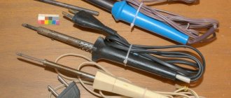
To perform various electrical work and assemble electronic circuits, a tool such as an electric soldering iron is often used. Its simplest type, which can be purchased at any hardware store, usually has a basic design.
It includes a heating element, a tip, a handle, usually wooden, and a power cable or cord. In some versions, the soldering iron can be equipped with several replaceable tips.
The power of such a soldering iron is fixed, most often 40 or 60 watts. But it is more convenient to use a tool with the ability to adjust power. Such models are also produced, although they are more expensive.
Why increase power?
To perform soldering work, tools with different parameters are required.
At the same time, it is impractical to have several soldering irons with different power and, accordingly, with different tip heating temperatures. When mounting components on a board, the tip temperature is required to be sufficient to warm the leads and melt the solder. Increased temperatures can lead to burning of individual elements, peeling of conductive paths from the board, and damage to wire insulation.
At the same time, using a soldering iron with lower power, and therefore with a lower heating temperature of the tip, allowing it to achieve a given value, forces you to increase the exposure time on the parts and solder.
As a result, prolonged heating causes components to fail, and the insulation may crack over time due to loss of mechanical properties.
Conclusion: when soldering, if heating of large areas and massive parts is required, it is necessary to increase not the temperature, but the power of the soldering iron, reducing to the possible minimum the time of contact of the tip with the leads of the part.
In this case, the solder must melt and provide reliable contact with the part, which in this mode will not be subject to overheating.
Soldering iron with adjustable tip temperature: diagrams, types, application – Turner
To perform various electrical work and assemble electronic circuits, a tool such as an electric soldering iron is often used. Its simplest type, which can be purchased at any hardware store, usually has a basic design.
It includes a heating element, a tip, a handle, usually wooden, and a power cable or cord. In some versions, the soldering iron can be equipped with several replaceable tips.
The power of such a soldering iron is fixed, most often 40 or 60 watts. But it is more convenient to use a tool with the ability to adjust power. Such models are also produced, although they are more expensive.
DIY power regulator for a soldering iron - diagrams and installation options
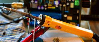
There are many models of soldering irons in stores - from cheap Chinese ones to expensive ones with a built-in temperature controller; they even sell soldering stations.
Another thing is, is the same station needed if such work needs to be done once a year, or even less often? It's easier to buy an inexpensive soldering iron. And some people still have simple but reliable Soviet instruments at home. A soldering iron that is not equipped with additional functionality heats up as long as the plug is plugged in.
And when turned off, it cools down quickly. An overheated soldering iron can ruin the work: it becomes impossible to solder anything firmly, the flux quickly evaporates, the tip oxidizes and the solder rolls off it.
To make work more comfortable, you can assemble a power regulator with your own hands, which will limit the voltage and thereby prevent the soldering iron tip from overheating.
Heating control
To heat a massive part to the required temperature, you need an equally massive soldering iron tip so that the heating rate is higher than the heat removal rate of the part.
A tool that can simultaneously cope with the tasks posed above is a fairly powerful soldering iron with temperature control.
That is, the maximum power of the soldering iron should be sufficient to heat large leads, and the temperature should be regulated within certain limits and selected in accordance with the operating conditions.
Then the massive tip will have greater thermal inertia and will heat the part to the required degree, without the risk of overheating.
There are several ways to adjust the temperature of the soldering iron:
- maximum-minimum heating (simple switch);
- dimmer adjustment;
- the use of control microcircuits in the handle of the device;
- external control unit;
- using a hair dryer.
Using an adjustable soldering iron, in addition to the advantages described above, you can significantly save on electricity consumption for large volumes of work performed, extend the life of the device due to less time operating at maximum power, and reduce the amount of harmful substances released during high-temperature soldering.
Types of regulators
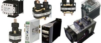
Devices for connecting various types of radio components have several types of characteristics. Soldering stations with heat and load adjustments are produced by the manufacturer with different parameter settings. Main varieties:
- Changing the voltage and power of the node is possible using a triac. This modification is most common when using heating components in radio engineering.
- Thyristor type adjusting element.
- Modification to increase the performance of the device allows you to change the output force to the required values.
- The indication makes it possible to recognize in which mode the heating is being carried out.
- Low-voltage controllers are used in designs designed to operate with a voltage of no more than 36 Volts.
https://youtube.com/watch?v=et60fwS8w5E
You can probably make components that have adjustable temperature volumes with your own hands. A simple structure without interference is used, which makes it possible to extend the service life of the heating element. The galvanic component is considered reliable; its versatility allows the design to be used with various modifications and models.
Switches and Dimmers
The simplest temperature control is used in soldering irons with a switch that allows only two positions, and, accordingly, two temperature values.
At the minimum value, the soldering iron mounted on the stand simply maintains the tip in a heated state, and when you press a key or button, the tip heats up to the maximum temperature at which soldering is performed.
Obviously, of the advantages described above, such a soldering iron only has the ability to save energy. The main task of adjustment - the production of high-quality and safe installation of components - remains impossible.
The second type of adjustable soldering irons is dimmable. Their design involves inserting a dimmer into the break in the power cable - a device that limits the power consumption of the soldering iron.
In this case, it really becomes possible to adjust the temperature of the tip, but this is done due to a voltage drop in the dimmer.
Accordingly, there can be no talk of any cost-effectiveness of such a scheme. But the price of such devices is quite low and can play a decisive role in the choice.
DIY device design
As follows from examination of the circuit, it consists of a power section, which should be mounted using surface-mounted installation, and a control circuit on a printed circuit board. By the way, they can solder the board at Solderpoint.ru.
Creating a PCB involves making a design of the board. For this purpose, the so-called LUT, which means laser-iron technology, is usually used in everyday conditions. The PCB manufacturing method includes the following steps:
- creating a drawing;
- transferring the design to the board blank;
- etching;
- cleaning;
- drilling holes;
- tinning of conductors.
To create an image of a board, the Sprint Layout program is most often used. After receiving the design using a laser printer, it is transferred to the foil getinax using a heated iron. Then the excess foil is etched using ferric chloride and the pattern is cleaned. Holes are drilled in the right places and the conductors are tinning. The elements of the control circuit are placed on the board and they are soldered (there are certain recommendations on how to solder correctly with a soldering iron).
Assembling the power part of the circuit includes connecting resistors R5, R6 and diode VD2 to the thyristor.
The last stage of assembly is placing the power section and control circuit board in the housing. The order of placement in the housing depends on its type.
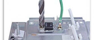
Since the dimensions of the power regulator elements on a triac are small and there are few of them, you can use, for example, a plastic socket as a housing. The largest place there is occupied by a variable adjustment resistor and a powerful thyristor. However, as experience shows, all the elements of the circuit, together with the printed circuit board, fit into such a housing.
Control units
The next type of soldering irons are more complex devices with a power supply, in which regulation occurs using a block of semiconductors and microcircuits. This unit is compact and can be located in the body of the soldering iron handle, which is very convenient.
The regulator may also be located on the handle. At a fairly modest price, this is a completely acceptable option that allows you to produce high-quality soldering.
Another type of adjustable soldering irons are tools with an external power supply. Thanks to the presence of these blocks, it is possible to operate the device on rectified direct current with stable voltage values.
Such a power supply also serves as a temperature stabilizer for the soldering iron, which will remain unchanged no matter how much the voltage in the network changes. Many radio components require this particular soldering mode.
The disadvantages of the models can be considered bulkiness and low mobility, but if you take into account that high-quality installation can only be done in an equipped workshop, and not “on the knee,” as is commonly said in such cases, then you can turn a blind eye to this.
The most precise adjustment and tuning can only be achieved using a soldering station, where a hair dryer is provided to assist a regular soldering iron, which is used to preheat the board or solder.
DIY soldering iron power regulator: proven working circuits (6 pcs)
Not everyone likes to buy unknown things. And some people find it more pleasant to make a soldering iron power regulator with their own hands, because this is also experience. Most circuits are assembled using triacs and thyristors; now they are easier to find than transistors. They are also easier to work with, since they are either open or closed, which allows you to make circuits simpler.
Choose any case
Simple thyristor circuits
When choosing a power regulator circuit for a soldering iron, two things are important: power and parts availability. The soldering iron power regulator presented below is assembled using widely used parts that are not a problem to find. The maximum current is 10 A, which is more than enough to perform any kind of work and for soldering irons with a power of up to 100 W. The thyristor in this circuit is used KU202n
Pay attention to the bridge connection. There are many circuits with connection errors
This option is working. Tested more than once.
Temperature controller circuit for a soldering iron using a thyristor
When assembling the circuit, be sure to place the thyristor on the radiator; the larger it is, the better. The circuit is simple, but when it is turned on, it creates interference. You can’t listen to the radio nearby, and to remove interference, we connect a 200 pF capacitor in parallel with the load, and a choke in series. The choke parameters are selected depending on the regulated load, but since soldering irons are usually no more than 80-100 W, the choke can be made at 100 W. To do this, you will need a ferrite ring with an outer diameter of 20 mm, on which about 100 turns are wound with a wire with a cross-section of 0.4 mm².
Another drawback of the diagram translated above is that the soldering iron “itches” noticeably. Sometimes you can put up with this, sometimes you can’t. To eliminate this phenomenon, you can select the parameters of capacitor C1 so that when the variable resistor is set to maximum, the connected lamp barely glows.
On other elements but also without interference
The above regulator can be used for any load. Let's give another analogue, but using a different element base. You can regulate not only the power/temperature of the soldering iron, but also any other load with a small inductive component.
A modified circuit for regulating the power of a soldering iron and any other load with the ripple effect eliminated
There is pulsation here, but its frequency is high and it will not be perceived by our vision. So it can be used not only as a dimmer for a soldering iron, but also to regulate the light from a regular incandescent lamp. Is a diode bridge needed to regulate the heating power of a soldering iron? It won't hurt, but it's not necessary.
On a thyristor with high sensitivity
This circuit allows you to smoothly change the temperature of the soldering iron from 50% to 100%. There are two indicators - power and power. The power presence LED always lights up when turned on, but at 75% power the glow is brighter. The power indicator changes the intensity of the glow depending on the operating mode.
Popular articles Evening necklace for bustier dress
Power regulator for soldering iron without interference
In order for the regulator to fit into the case of a mobile phone charger, resistances are used of SMD type (1206). All resistors are installed on the board, except for R 10. Some can be composite (we assemble the required value from series-connected resistors).
For normal operation of the circuit, a sensitive thyristor (with a low control current) and a low state holding current (about 1 mA) is required. For example, KT503 (designed for voltage 400 V, control current 1 mA). The rest of the element base is indicated in the diagram.
If assembled, but the voltage is not adjustable
If the assembled regulator does not regulate anything - the temperature of the soldering iron does not change - the problem is in the thyristor. The scheme seems to be working, but nothing happens. The reason is a thyristor with low sensitivity. The currents flowing in the circuit are not sufficient to open. In this case, it is worth installing an analogue with higher sensitivity (lower control currents).
One of the housing options in which you can hide a homemade power regulator for a soldering iron
The regulator may still work, but the soldering iron begins to “itch.” This problem is solved by installing a choke at the output (in front of the soldering iron). The capacity must be selected - it depends on the soldering iron. The second solution is an analog control circuit, and this is a different circuit.
Well, if you have problems with operation, look for either faulty parts or incorrectly selected components. This is usually the problem.
Temperature controller circuit for a soldering iron
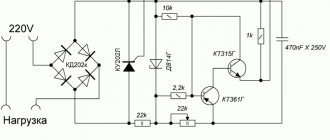
Below is a simple diagram of a power regulator:
I used this circuit for my regulator about 20 years ago, I still use this soldering iron. Of course, some parts, such as transistors, a neon light bulb, can be replaced with modern ones.
Device details:
- Transistors; KT 315G, MP 25 can be replaced with KT 361B
- Thyristor; KU 202N
- Zener diode; D 814B or with the letter B
- Diode;KD 202Zh
- Fixed resistors: MLT-3k, 2k-2 pcs, 30k, 100 ohm, 470k
- Variable resistor; 100k
- Capacitor; 0.1 µF
As you can see, the device diagram is very simple. Even a beginner can repeat it.
Making a simple soldering iron temperature controller with your own hands
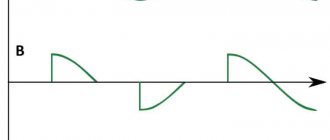
The presented device is built according to the so-called half-wave power regulator. That is, with the thyristor VS 1 fully open, which is controlled by transistors VT 1 and VT 2, one half-wave of the mains voltage passes through the diode VD 1, and the other half-wave through the thyristor. If you turn the slider of the variable resistor R 2 in the opposite direction, then the thyristor VS 1 will close, and the load will have one half-wave that will pass through the diode VD 1:
Therefore, it is impossible to reduce the voltage below 110 volts with this regulator. As practice shows, this is not necessary, since at minimum voltage the temperature of the tip is so low that the tin barely melts.
The part ratings presented in the diagram are selected to work together with high-power soldering irons. If you do not need this, then the power elements, thyristor and diode can be replaced with less powerful ones. If you do not have a two-watt resistor R 5 with a nominal value of 30 kilo ohms, then it can be made up of two series-connected resistors of 15 kilo ohms, like mine:
This device does not require configuration. When assembled correctly and from serviceable parts, it starts working immediately.
Attention! Be careful. This temperature controller does not have galvanic isolation over the network
Secondary circuits have high potential.
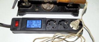
All that remains is to choose the appropriate housing size. Place the soldering iron socket:
It is not necessary to take the fuse out; for example, I have it soldered into the break in the power cord. But the variable resistor needs to be installed in a convenient place and, of course, the scale must be calibrated, for example, in volts:
The resulting regulator is very reliable, which has been tested by time, and it will serve you for many years, and the soldering iron will thank you.
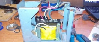
DIY temperature regulator
Making a soldering iron with do-it-yourself adjustment requires knowledge of electrical engineering. If you have experience, it is proposed to make the mechanism from a conventional heating element with a power of 60 watts. High-quality connections can only be made when using a heating value balancer. Assembly is carried out by implementing some modifications and involves the use of available materials. The simplest system includes:
- thyristor model KU101G;
- resistor SP – 1;
- diode operating at a current of at least 1A.
Thermostat circuit for a low-voltage soldering iron
Installation of the model is possible without the use of a board, in a power supply housing of any size. The connection is placed on the resistor body, to which the connector for adjusting the degree of heating is adjacent. The result is an adjustable device with an output power of up to 60 watts. A schematic drawing for more powerful devices includes slightly different components. Assembly is carried out on a circuit board; variable resistor R2 is responsible for adjustment, which operates in the range from 50 to 100%. The maximum permissible load is 300 watts, sufficient for a household device. Circuit options depending on the power limiter The power of the device can be adjusted in several ways, the differences lie in the use of a semiconductor controller that performs the necessary tasks. Schemes can be built using several components, depending on the purpose:
- The thyristor works like an electronic switch; the current starts in one direction. The structure is made with three outputs, a cathode, an anode, and a control electrode. Applying a pulse to the electrode causes the thyristor to open; closing occurs after stopping the supply or changing the direction of the current.
- Semiconductors that conduct current in both directions are called triacs. The housing has a control gate and power electrodes; the operation is essentially similar to two connected thyristors.
- The design of control sensors uses parts known to radio amateurs, such as a resistor, diode, capacitor, and microcontroller.
In most cases, a thyristor or triac is used, the precise debugging is regulated using a microcontroller added to the circuit.
Converters based on controlled diodes
Each of the possible versions of the devices differs in its circuit and control element. There are circuits of power regulators using thyristors, triacs and other options.
Thyristor devices
In terms of their circuit design, most known control units are manufactured using a thyristor circuit controlled by a voltage specially generated for these purposes.
Popular articles Ear on the fire
A two-mode regulator circuit based on a low-power thyristor is shown in the photo.
Using such a device, it is possible to control soldering irons whose power does not exceed 40 watts. Despite its small dimensions and the absence of a ventilation module, the converter practically does not heat up under any permissible operating mode.
Such a device can operate in two modes, one of which corresponds to the standby state. In this situation, the handle of the variable resistor R4 is set to the extreme right position according to the diagram, and the thyristor VS2 is completely closed.
Power is supplied to the soldering iron through a chain with a VD4 diode, on which the voltage is reduced to approximately 110 Volts.
In the second operating mode, the voltage regulator (R4) is moved from the extreme right position; Moreover, in its middle position, thyristor VS2 opens slightly and begins to pass alternating current.
The transition to this state is accompanied by the ignition of the VD6 indicator, which is activated when the output supply voltage is about 150 Volts.
By further rotating the R4 regulator knob, it will be possible to smoothly increase the output power, raising its output level to the maximum value (220 Volts).
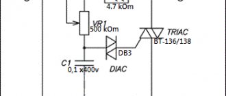
Triac converters
Another way to organize the control of a soldering iron involves the use of an electronic circuit built on a triac and also designed for a low-power load.
This circuit works on the principle of reducing the effective voltage value on the semiconductor rectifier, to which the payload (soldering iron) is connected.
The state of the control triac depends on the position of the “switch” of the variable resistor R1, which changes the potential at its control input. When the semiconductor device is completely open, the power supplied to the soldering iron is reduced by approximately half.
The simplest control option
The simplest voltage regulator, which is a “truncated” version of the two circuits discussed above, involves mechanical control of power in the soldering iron.
Such a power regulator is in demand in conditions where long breaks in work are expected and it does not make sense to keep the soldering iron on all the time.
In the open position of the switch, a small amplitude voltage (approximately 110 Volts) is supplied to it, ensuring a low heating temperature of the tip.
To bring the device into working condition, just turn on the S1 toggle switch, after which the soldering iron tip quickly heats up to the required temperature, and you can continue soldering.
Such a thermostat for a soldering iron allows you to reduce the temperature of the tip to a minimum value in the intervals between solderings. This feature slows down oxidative processes in the tip material and significantly extends its service life.
The simplest energy regulator
The first designs of devices that varied the power supplied to a load were based on Ohm's law: electrical power equals current times voltage or resistance times current squared. A device called a rheostat was designed on this principle. It is located both in series and in parallel with the connected load. By changing its resistance, the power is also adjusted.
The current entering the rheostat is divided between it and the load. When connected in series, the current and voltage are controlled, and when connected in parallel, only the value of the potential difference is controlled. Depending on the material from which the resistance is made, rheostats can be:
- metal;
- liquid;
- coal;
- ceramic.
According to the law of conservation of energy, the absorbed electrical energy cannot simply disappear, therefore, in resistors, power is converted into heat, and if its value is large, it must be removed from them. To ensure removal, cooling is used, which is performed by blowing or by immersing the rheostat in oil.
A rheostat is a fairly universal device. Its only, but significant, disadvantage is the generation of heat, which does not allow making a device with small dimensions if it is necessary to pass large amounts of power through it. By controlling current and voltage, a rheostat is often used in low-power lines of household appliances. For example, in audio equipment to adjust the volume. It is not at all difficult to make such a current regulator with your own hands; this applies to a greater extent to a wire rheostat.
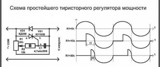
Classic thyristor regulator circuit
The classic thyristor circuit of the soldering iron power regulator did not meet one of my main requirements, the absence of radiating interference into the power supply network and the airwaves. But for a radio amateur, such interference makes it impossible to fully engage in what he loves. If the circuit is supplemented with a filter, the design will turn out to be bulky. But for many use cases, such a thyristor regulator circuit can be successfully used, for example, to adjust the brightness of incandescent lamps and heating devices with a power of 20-60 W. That's why I decided to present this diagram.
In order to understand how the circuit works, I will dwell in more detail on the principle of operation of the thyristor. A thyristor is a semiconductor device that is either open or closed. to open it, you need to apply a positive voltage of 2-5 V to the control electrode, depending on the type of thyristor, relative to the cathode (indicated by k in the diagram). After the thyristor has opened (the resistance between the anode and cathode becomes 0), it is not possible to close it through the control electrode. The thyristor will be open until the voltage between its anode and cathode (labeled a and k in the diagram) becomes close to zero. It's that simple.
Popular articles Butterflies
The classical regulator circuit works as follows. AC mains voltage is supplied through the load (incandescent light bulb or soldering iron winding) to a rectifier bridge circuit made using diodes VD1-VD4. The diode bridge converts alternating voltage into direct voltage, varying according to a sinusoidal law (diagram 1). When the middle terminal of resistor R1 is in the extreme left position, its resistance is 0 and when the voltage in the network begins to increase, capacitor C1 begins to charge. When C1 is charged to a voltage of 2-5 V, current will flow through R2 to the control electrode VS1. The thyristor will open, short-circuit the diode bridge and the maximum current will flow through the load (top diagram).
When you turn the knob of the variable resistor R1, its resistance will increase, the charging current of capacitor C1 will decrease and it will take more time for the voltage on it to reach 2-5 V, so the thyristor will not open immediately, but after some time. The greater the value of R1, the longer the charging time of C1 will be, the thyristor will open later and the power received by the load will be proportionally less. Thus, by rotating the variable resistor knob, you control the heating temperature of the soldering iron or the brightness of the incandescent light bulb.
Above is a classic circuit of a thyristor regulator made on a KU202N thyristor. Since controlling this thyristor requires a larger current (according to the passport 100 mA, the real one is about 20 mA), the values of resistors R1 and R2 are reduced, R3 is eliminated, and the size of the electrolytic capacitor is increased. When repeating the circuit, it may be necessary to increase the value of capacitor C1 to 20 μF.