GOST 26258-87
Group G23
STATE STANDARD OF THE USSR UNION
CYLINDRICAL COMBINES FOR PROCESSING SUPPORTING SURFACES FOR FASTENING PARTS
Specifications
Counterbores designed for working bearing surfaces under fastenings. Specifications
OKP 39 1650
Validity period from 01.01.89 to 01.01.94* _______________________________ * The validity period was lifted according to Protocol N 3-93 of the Interstate Council for Standardization, Metrology and Certification (IUS N 5-6, 1993). — Note from the database manufacturer.
INFORMATION DATA
1. DEVELOPED AND INTRODUCED by the Ministry of Machine Tool and Tool Industry of the USSR
PERFORMERS
D.I.Semenchenko, Ph.D. tech. sciences; G.A.Astafieva, Ph.D. tech. sciences; N.I.Minaeva, N.A.Kopteva
2. APPROVED AND ENTERED INTO EFFECT by Resolution of the USSR State Committee on Standards dated November 24, 1987 N 4242
3. Inspection period - 1993, inspection frequency - 5 years
4. INSTEAD GOST 26258-84
5. REFERENCE REGULATIVE AND TECHNICAL DOCUMENTS
| Designation of the referenced technical document | Item number |
| GOST 8.051-81 | 4.2 |
| GOST 1050-74 | 2.2; 2.7; 4.6 |
| GOST 1412-85 | 4.6 |
| GOST 1477-84 | 1.4; 1.5 |
| GOST 2848-75 | 1.8 |
| GOST 3009-78 | 1.10 |
| GOST 3882-74 | 2.7 |
| GOST 4543-71 | 2.2; 2.7 |
| GOST 5915-70 | 1.5; 1.6 |
| GOST 9013-59 | 2.21 |
| GOST 9.014-78 | 4.1 |
| GOST 9378-75 | 4.4 |
| GOST 9472-83 | 1.9 |
| GOST 11284-75 | 4.6 |
| GOST 12876-67 | Introductory part |
| GOST 14034-74 | 1.7 |
| GOST 15527-70 | 2.9 |
| GOST 16093-81 | 1.11 |
| GOST 18088-83 | 2.19, 2.20, 5 |
| GOST 19265-73 | 2.2 |
| GOST 23726-79 | 3.1 |
| GOST 24705-81 | 1.11 |
| GOST 25400-82 | 1.3, 2.8 |
| GOST 25557-82 | 1.8 |
| GOST 25706-83 | 4.4 |
| GOST 26259-87 | 1.3-1.6 |
| GOST 26260-84 | 1.3; 1.5 |
This standard applies to cylindrical counterbores intended for processing supporting surfaces for fasteners in accordance with GOST 12876-67, except for counterbores for enlarged washers for processing supporting surfaces with a diameter of over 61 mm and protruding supporting surfaces with a diameter of up to 15 mm.
Purpose of the tool
The principle of operation of the counterbore is similar to the operation of another processing tool - a countersink.
Countering is very rarely used manually due to the low accuracy of this processing method. Depending on the nature of the work, it is installed on the following machines:
- drilling;
- milling;
- boring;
- turning
The tool is most widely used as a processing tool on drilling-type machines.
The sharp elements of the counterbore are located in the end part. They are evenly distributed around the perimeter of the main shaft, which rotates around its axis. This design caused the spread of the tool for use on drilling rigs.
Countering metal can pursue the following purposes:
- obtaining a perfectly flat reference plane located at an angle of 90° relative to the hole;
- elimination of defects in the inner surface of holes;
- chamfering an edge;
- grinding of sagging and burrs of metal;
- creating multi-stage holes.
The tool has no requirements for the material of the workpiece. It copes equally well with all types of ferrous and non-ferrous metals, as well as alloys based on them.
The accuracy of work meets modern standards used in the production of precision engineering parts up to accuracy class 2.
TYPES AND MAIN SIZES
1.1. Counterbodies must be manufactured of the following types:
1 - with a permanent guide pin and a cylindrical shank;
2 - with a replaceable guide pin and a conical shank;
3 - mounted with a replaceable guide pin;
4 - with a replaceable guide pin and a shank for a pin lock.
Counterbodies types 2-4 are manufactured in two versions:
1 — counterbores with a working part made of high-speed steel;
2 - counterbores with a working part equipped with carbide plates.
Type 1 counterbores are manufactured only in the 1st version.
1.2. Counters with a working part made of high-speed steel are designed for processing structural steel, with a working part equipped with carbide inserts for processing structural steel and cast iron.
1.3. The design and main dimensions of the bores must correspond to those indicated in Figure 1 and Table 1 for bores of type 1;
in drawings 2, 3 and in table 2 for counterbores of type 2;
in drawings 4, 5 and in table 3 for counterbores of type 3;
in drawings 6, 7 and in table 4 for counterbores of type 4.
Type 1
Counterbore with permanent guide pin and cylindrical shank
Damn.1
Table 1
mm
| Counterbore designation | Applicability | ||||||
| 2350-0621 | 2,2 | 1,1 | 2,2 | 45 | 7 | — | 1,5 |
| 2350-0622 | 1,2 | ||||||
| 2350-0623 | 2,5 | 1,3 | 2,5 | ||||
| 2350-0624 | 1,4 | ||||||
| 2350-0625 | 2,8 | 1,5 | 2,8 | ||||
| 2350-0626 | 1,6 | ||||||
| 2350-0627 | 3,3 | 1,7 | 3,3 | 56 | 10 | 2,5 | |
| 2350-0628 | 1,8 | ||||||
| 2350-0629 | 3,8 | 2,0 | 3,8 | ||||
| 2350-0631 | 2,1 | ||||||
| 2350-0632 | 4,3 | 2,2 | 4,3 | ||||
| 2350-0633 | 2,4 | ||||||
| 2350-0634 | 5,0 | 1,7 | 5,0 | ||||
| 2350-0635 | 1,8 | ||||||
| 2350-0636 | 2,0 | ||||||
| 2350-0637 | 2,7 | ||||||
| 2350-0638 | 2,9 | ||||||
| 2350-0639 | 6,0 | 2,2 | 71 | 14 | 31,5 | 4,0 | |
| 2350-0641 | 2,4 | ||||||
| 2350-0642 | 2,6 | ||||||
| 2350-0643 | 3,2 | ||||||
| 2350-0644 | 3,4 | ||||||
| 2350-0645 | 6,5 | 3,7 | |||||
| 2350-0646 | 3,9 | ||||||
| 2350-0647 | 7,0 | 2,7 | 3,0 | ||||
| 2350-0648 | 2,9 | ||||||
| 2350-0649 | 3,1 | ||||||
| 2350-0651 | 7,5 | 2,7 | |||||
| 2350-0652 | 2,9 | ||||||
| 2350-0653 | 3,1 | ||||||
| 2350-0654 | 8,0 | 3,2 | 4,0 | ||||
| 2350-0655 | 3,4 | ||||||
| 2350-0656 | 3,6 | ||||||
| 2350-0657 | 4,3 | 5,0 | |||||
| 2350-0658 | 4,5 | ||||||
| 2350-0659 | 10,0 | 4,3 | 8,0 | 80 | 18 | 35,5 | |
| 2350-0661 | 4,5 | ||||||
| 2350-0662 | 4,8 | ||||||
| 2350-0663 | 5,3 | 6,0 | |||||
| 2350-0664 | 5,5 | ||||||
| 2350-0665 | 11,0 | 5,3 | |||||
| 2350-0666 | 5,5 | ||||||
| 2350-0667 | 5,8 | ||||||
| 2350-0668 | 6,4 | ||||||
| 2350-0669 | 6,6 | ||||||
| 2350-0671 | 12,0 | 4,3 | 5,0 | ||||
| 2350-0672 | 4,5 | ||||||
| 2350-0673 | 5,3 | 6,0 | |||||
| 2350-0674 | 5,5 | ||||||
| 2350-0675 | 5,8 | ||||||
| 2350-0676 | 13,5 | 6,4 | 12,5 | 100 | 22 | 40,0 | |
| 2350-0677 | 6,6 | ||||||
| 2350-0678 | 7,0 | ||||||
| 2350-0679 | 15,0 | 5,3 | |||||
| 2350-0681 | 5,5 | ||||||
| 2350-0682 | 8,4 | 9,0 | |||||
| 2350-0683 | 9,0 | ||||||
| 2350-0684 | 16,0 | 5,3 | 6,0 | ||||
| 2350-0685 | 5,5 | ||||||
| 2350-0686 | 5,8 | ||||||
| 2350-0687 | 18,0 | 6,4 | |||||
| 2350-0688 | 6,6 | ||||||
| 2350-0689 | 7,0 | ||||||
| 2350-0691 | 8,4 | 10,0 | |||||
| 2350-0692 | 9,0 | ||||||
| 2350-0693 | 10,0 | ||||||
| 2350-0694 | 10,5 | ||||||
| 2350-0695 | 11,0 | ||||||
| 2350-0696 | 20,0 | 8,4 | |||||
| 2350-0697 | 9,0 | ||||||
| 2350-0698 | 10,0 | ||||||
| 2350-0699 | 10,5 | ||||||
| 2350-0701 | 11,0 | ||||||
| 2350-0702 | 12,0 | ||||||
| 2350-0703 | 13,0 | 15,0 | |||||
| 2350-0704 | 14,0 | ||||||
| 2350-0705 | (13,5) |
An example of a symbol for a type 1 counterbore with a diameter of the working part = 5.0 mm, a diameter of the guide pin = 2.0 mm:
Counterbore 2350-0636
GOST 26258-87
Type 2
Counterbore with replaceable guide pin and tapered shank
________________
*Size for reference.
** It is allowed to place the screw axis (pos. 3) perpendicular to the supporting plane of the guide pin shank (pos.2
).
1
- counterbore;
2
— guide pin type 1 according to GOST 26259-87;
3
— screw according to GOST 1477-84;
4
- carbide plate according to GOST 25400-82
Damn.2
1.4. Design and main dimensions of the counterbores (pos. 1
) must correspond to those indicated in Figure 3 and Table 2.
Damn.3
table 2
mm
| Designation of execution counterbore | Applicability of counterbore design | * | Morse cone | Part designation | ||||||||||
| 1 | 2 | 1 | 2 | Pos.2 Trunnion according to GOST 26259-87 | Pos.3 Screw according to GOST 1477-84 | |||||||||
| 2350-0706 | 2350-0707 | 13,5 | 138 | 4 | M3 | 132 | 22 | 30 | 16 | 2 | 6020-0524 to 6020-0526 | |||
| 2350-0708 | 2350-0709 | 15,0 | 137 | 6020-0521 | ||||||||||
| 6020-0522 | ||||||||||||||
| 139 | 6020-0527 | |||||||||||||
| 6020-0528 | ||||||||||||||
| 2350-0711 | 2350-0712 | 16,0 | 138 | 6020-0521 to 6020-0523 | ||||||||||
| 2350-0713 | 2350-0714 | 18,0 | 146 | 5 | M4 | 140 | 25 | 38 | 19 | 6020-0529 to 6020-0532 | ||||
| 147 | 6020-0533 to 6020-0535 | |||||||||||||
| 148 | 6020-0536 | |||||||||||||
| 6020-0537 | ||||||||||||||
| 2350-0715 | 2350-0716 | 20,0 | 147 | 6020-0533 to 6020-0535 | ||||||||||
| 148 | 6020-0536 to 6020-0538 | |||||||||||||
| 150 | 6020-0539 to 6020-0542 | |||||||||||||
| 2350-0744 | 2350-0745 | 22,0 | 158 | 6 | M5 | 150 | 30 | 46 | 23 | 6020-0546 to 6020-0548 | ||||
| 2350-0717 | 2350-0718 | 24,0 | 157 | 6020-0543 to 6020-0545 | ||||||||||
| 158 | 6020-0546 | |||||||||||||
| 6020-0547 | ||||||||||||||
| 160 | 6020-0549 to 6020-0556 | |||||||||||||
| 2350-0719 | 2350-0721 | 26,0 | 190 | 8 | M6 | 180 | 35 | 54 | 27 | 3 | 6020-0561 to 6020-0567 | |||
| 192 | 6020-0568 to 6020-0572 | |||||||||||||
| 2350-0722 | 2350-0723 | 28,0 | 188 | 6020-0557 to 6020-0559 | ||||||||||
| 190 | 6020-0561 to 6020-0565 | |||||||||||||
| 2350-0724 | 2350-0725 | 30,0 | 190 | 6020-0561 to 6020-0567 | ||||||||||
| 192 | 6020-0568 to 6020-0575 | |||||||||||||
| 2350-0777 | 2350-0778 | 32,0 | 202 | 10 | M8 | 190 | 40 | 64 | 32 | 6020-0594 | ||||
| 6020-0596 | ||||||||||||||
| 6020-0598 | ||||||||||||||
| 2350-0726 | 2350-0727 | 33,0 | 6020-0585 | |||||||||||
| 6020-0587 | ||||||||||||||
| 6020-0589 | ||||||||||||||
| 6020-0592 | ||||||||||||||
| 6020-0594 | ||||||||||||||
| 2350-0728 | 2350-0729 | 34,0 | 200 | 6020-0576 | ||||||||||
| 6020-0578 | ||||||||||||||
| 6020-0581 | ||||||||||||||
| 202 | 6020-0583 | |||||||||||||
| 6020-0585 | ||||||||||||||
| 6020-0587 | ||||||||||||||
| 6020-0589 | ||||||||||||||
| 6020-0592 | ||||||||||||||
| 6020-0594 | ||||||||||||||
| 205 | 6020-0598 | |||||||||||||
| 6020-0601 | ||||||||||||||
| 2350-0731 | 2350-0732 | 36,0 | 202 | 10 | M8 | 190 | 40 | 64 | 32 | 6020-0594 | ||||
| 6020-0596 | ||||||||||||||
| 205 | 6020-0598 | |||||||||||||
| 6020-0601 | ||||||||||||||
| 6020-0603 | ||||||||||||||
| 6020-0605 | ||||||||||||||
| 2350-0733 | 2350-0734 | 38,0 | 202 | 6020-0585 | ||||||||||
| 6020-0587 | ||||||||||||||
| 6020-0589 | ||||||||||||||
| 6020-0592 | ||||||||||||||
| 6020-0594 | ||||||||||||||
| 6020-0596 | ||||||||||||||
| 2350-0735 | 2350-0736 | 40,0 | 205 | 6020-0598 | ||||||||||
| 6020-0601 | ||||||||||||||
| 6020-0603 | ||||||||||||||
| 6020-0605 | ||||||||||||||
| 6020-0607 | ||||||||||||||
| 208 | 6020-0609 | |||||||||||||
| 2350-0737 | 2350-0738 | 42,0 | 248 | 12 | 236 | 50 | 76 | 42 | 4 | 6020-0612 | ||||
| 6020-0613 | ||||||||||||||
| 251 | 6020-0614 | |||||||||||||
| 6020-0615 | ||||||||||||||
| 6020-0617 | ||||||||||||||
| 6020-0618 | ||||||||||||||
| 254 | 6020-0619 | |||||||||||||
| 6020-0621 | ||||||||||||||
| 2350-0739 | 2350-0741 | 43,0 | 251 | 12 | M8 | 236 | 50 | 76 | 42 | 6020-0616 | ||||
| 6020-0617 | ||||||||||||||
| 254 | 6020-0619 | |||||||||||||
| 2350-0742 | 2350-0743 | 45,0 | 251 | 6020-0614 | ||||||||||
| 6020-0615 | ||||||||||||||
| 6020-0616 | ||||||||||||||
| 6020-0617 | ||||||||||||||
| 254 | 6020-0619 to 6020-0622 | |||||||||||||
| 2350-0746 | 2350-0747 | 48,0 | 251 | 6020-0616 to 6020-0618 | ||||||||||
| 254 | 6020-0619 to 6020-0623 | |||||||||||||
| 258 | 6020-0624 | |||||||||||||
| 6020-0625 | ||||||||||||||
| 2350-0748 | 2350-0749 | 52,0 | 265 | 16 | M10 | 250 | 63 | 88 | 53 | 6020-0641 | ||||
| 268 | 6020-0643 | |||||||||||||
| 6020-0645 | ||||||||||||||
| 6020-0647 | ||||||||||||||
| 272 | 6020-0652 | |||||||||||||
| 2350-0804 | 2350-0805 | 53,0 | 6020-0656 | |||||||||||
| 6020-0661 | ||||||||||||||
| 2350-0751 | 2350-0752 | 55,0 | 268 | 6020-0649 | ||||||||||
| 272 | 6020-0654 | |||||||||||||
| 2350-0753 | 2350-0754 | 57,0 | 6020-0658 | |||||||||||
| 6020-0663 | ||||||||||||||
| 6020-0667 | ||||||||||||||
| 2350-0755 | 2350-0756 | 60,0 | 268 | 6020-0645 | ||||||||||
| 6020-0647 | ||||||||||||||
| 6020-0649 | ||||||||||||||
| 272 | 6020-0652 | |||||||||||||
| 6020-0654 | ||||||||||||||
| 6020-0656 | ||||||||||||||
| 6020-0658 | ||||||||||||||
| 6020-0661 | ||||||||||||||
| 6020-0665 | ||||||||||||||
| 6020-0669 | ||||||||||||||
| 277 | 6020-0672 | |||||||||||||
| 2350-0757 | 2350-0758 | 61,0 | 268 | 6020-0649 | ||||||||||
| 272 | 6020-0654 | |||||||||||||
| 6020-0658 | ||||||||||||||
| ________________ *Size for reference. | ||||||||||||||
An example of a symbol for a counterbore type 2, execution 1, diameter = 13.5 mm:
Counterbore 2350-0706
GOST 26258-87
The same, version 2 with plates made of hard alloy grade VK8:
Counterbore 2350-0707 VK8
GOST 26258-87
Type 3
Mounted counterbore with replaceable guide pin
________________
*Size for reference.
1
- counterbore;
2
— guide pin type 1 according to GOST 26259-87;
3
— mandrel according to GOST 26260-84;
4
— screw according to GOST 1477-84;
5
- carbide plate according to GOST 25400-82
Damn.4
1.5. Design and main dimensions of the counterbores (pos. 1
) must correspond to those indicated in Figure 5 and Table 3.
Damn.5
Table 3
mm
| Designation of execution counterbore | Applicability of counterbore execution | * | Part designation | |||||||
| 1 | 2 | 1 | 2 | Pos.2 Trunnion according to GOST 26259-87 | Pos.3 Mandrel according to GOST 26260-84 | Pos.4 Screw according to GOST 1477-84 | ||||
| 2350-0759 | 2350-0761 | 34,0 | 246,0 | 10 | 40 | 6020-0577 | 6230-0034 | |||
| 6020-0579 | ||||||||||
| 6020-0582 | ||||||||||
| 248,0 | 6020-0584 | |||||||||
| 6020-0586 | ||||||||||
| 6020-0588 | ||||||||||
| 6020-0591 | ||||||||||
| 6020-0593 | ||||||||||
| 6020-0595 | ||||||||||
| 251,0 | 6020-0599 | |||||||||
| 6020-0602 | ||||||||||
| 2350-0762 | 2350-0763 | 36,0 | 248,0 | 6020-0595 | ||||||
| 6020-0597 | ||||||||||
| 251,0 | 6020-0599 | |||||||||
| 6020-0602 | ||||||||||
| 6020-0604 | ||||||||||
| 6020-0606 | ||||||||||
| 2350-0764 | 2350-0765 | 38 | 248,0 | 6020-0586 | ||||||
| 6020-0588 | ||||||||||
| 6020-0591 | ||||||||||
| 6020-0593 | ||||||||||
| 6020-0595 | ||||||||||
| 6020-0597 | ||||||||||
| 251,0 | 6020-0599 | |||||||||
| 2350-0766 | 2350-0767 | 40,0 | 6020-0599 | |||||||
| 6020-0602 | ||||||||||
| 6020-0604 | ||||||||||
| 6020-0606 | ||||||||||
| 6020-0608 | ||||||||||
| 254 | 6020-0611 | |||||||||
| 2350-0768 | 2350-0769 | 42,0 | 282,5 | 13 | 50 | 6020-0626 | 6230-0038 | |||
| 6020-0627 | ||||||||||
| 285,5 | 6020-0628 | |||||||||
| 6020-0629 | ||||||||||
| 6020-0632 | ||||||||||
| 6020-0633 | ||||||||||
| 288,5 | 6020-0634 | |||||||||
| 6020-0635 | ||||||||||
| 2350-0771 | 2350-0772 | 43,0 | 285,5 | 6020-0631 | ||||||
| 6020-0632 | ||||||||||
| 288,5 | 6020-0634 | |||||||||
| 2350-0773 | 2350-0774 | 45,0 | 285,5 | 6020-0628 to 6020-0632 | ||||||
| 288,5 | 6020-0634 to 6020-0636 | |||||||||
| 2350-0775 | 2350-0776 | 48,0 | 285,5 | 6020-0631 to 6020-0633 | ||||||
| 288,5 | 6020-0634 to 6020-0637 | |||||||||
| 292,5 | 6020-0638 | |||||||||
| 6020-0639 | ||||||||||
| 2350-0779 | 2350-0781 | 52,0 | 285,0 | 16 | 6020-0642 | 6230-0036 | ||||
| 288,0 | 6020-0644 | |||||||||
| 6020-0646 | ||||||||||
| 6020-0648 | ||||||||||
| 292,0 | 6020-0653 | |||||||||
| 2350-0782 | 2350-0783 | 53,0 | 6020-0657 | |||||||
| 6020-0662 | ||||||||||
| 2350-0784 | 2350-0785 | 55,0 | 288,0 | 6020-0651 | ||||||
| 292,0 | 6020-0655 | |||||||||
| 6020-0659 | ||||||||||
| 2350-0786 | 2350-0787 | 57,0 | 6020-0664 | |||||||
| 6020-0668 | ||||||||||
| 2350-0788 | 2350-0789 | 60,0 | 288,0 | 6020-0646 | ||||||
| 6020-0648 | ||||||||||
| 6020-0651 | ||||||||||
| 292,0 | 6020-0653 | |||||||||
| 6020-0655 | ||||||||||
| 6020-0657 | ||||||||||
| 6020-0659 | ||||||||||
| 6020-0662 | ||||||||||
| 6020-0666 | ||||||||||
| 6020-0671 | ||||||||||
| 297,0 | 6020-0673 | |||||||||
| 2350-0791 | 2350-0792 | 61,0 | 288,0 | 6020-0651 | ||||||
| 292,0 | 6020-0655 | |||||||||
| 6020-0659 | ||||||||||
| ________________ *Size for reference. | ||||||||||
An example of a symbol for a counterbore type 3, version 1, with a diameter of =53 mm:
Counterbore 2350-0782
GOST 26258-87
The same, version 2 with plates made of hard alloy VK8:
Counterbore 2350-0783 VK8
GOST 26258-87
Type 4
Counterbore with replaceable guide pin and shank for pin lock
________________
*Size for reference.
1
- counterbore;
2
— guide pin type 2 according to GOST 26259-87;
3
— nut according to GOST 5915-70;
4
- carbide plate according to GOST 25400-82
Damn.6
1.6. Design and main dimensions of the counterbores (pos. 1
) must correspond to those indicated in Figure 7 and Table 4.
Damn.7
Table 4
mm
| Designation of execution counterbore | Applicability of counterbore design | * | Part designation | |||||||||
| 1 | 2 | 1 | 2 | Pos.2 Trunnion according to GOST 26259-87 | Pos.3 Nut according to GOST 5915-70 | |||||||
| 2350-0793 | 2350-0794 | 13,5 | 75 | 4 | 10 | 11 | 60 | 25 | 6020-0704 to 6020-0706 | M3 | ||
| 2350-0813 | 2350-0814 | 15,0 | 6020-0701 | |||||||||
| 6020-0702 | ||||||||||||
| 6020-0707 | ||||||||||||
| 6020-0708 | ||||||||||||
| 2350-0846 | 2350-0847 | 16,0 | 6020-0701 to 6020-0703 | |||||||||
| 2350-0795 | 2350-0796 | 18,0 | 85 | 5 | 16 | 70 | 35 | 6020-0709 to 6020-0717 | M4 | |||
| 2350-0797 | 2350-0798 | 20,0 | 6020-0713 to 6020-0722 | |||||||||
| 2350-0799 | 2350-0801 | 22,0 | 6 | 14 | 6020-0726 to 6020-0728 | M5 | ||||||
| 2350-0802 | 2350-0803 | 24,0 | 6020-0723 to 6020-0727 | |||||||||
| 6020-0729 to 6020-0736 | ||||||||||||
| 2350-0806 | 2350-0807 | 26,0 | 110 | 8 | 25 | 90 | 45 | 6020-0741 to 6020-0752 | M6 | |||
| 2350-0808 | 2350-0809 | 28,0 | 6020-0737 to 6020-0745 | |||||||||
| 2350-0811 | 2350-0812 | 30,0 | 20 | 6020-0741 to 6020-0755 | ||||||||
| 2350-0815 | 2350-0816 | 32,0 | 115 | 10 | 6020-0765 to 6020-0767 | M8 | ||||||
| 2350-0848 | 2350-0849 | 33,0 | 6020-0761 to 6020-0765 | |||||||||
| 2350-0851 | 2350-0852 | 34,0 | 6020-0756 to 6020-0765 | |||||||||
| 6020-0767 | ||||||||||||
| 6020-0768 | ||||||||||||
| 2350-0817 | 2350-0818 | 36,0 | 6020-0765 to 6020-0771 | |||||||||
| 2350-0819 | 2350-0821 | 38,0 | 6020-0761 to 6020-0767 | |||||||||
| 2350-0822 | 2350-0823 | 40,0 | 6020-0767 to 6020-0773 | M10 | ||||||||
| 2350-0824 | 2350-0825 | 42,0 | 12 | 25 | 6020-0774 to 6020-0777 | |||||||
| 6020-0779 | ||||||||||||
| 140 | 6020-0781 | |||||||||||
| 6020-0783 | ||||||||||||
| 2350-0826 | 2350-0827 | 43,0 | 6020-0778 | |||||||||
| 6020-0779 | ||||||||||||
| 6020-0782 | ||||||||||||
| 2350-0828 | 2350-0829 | 45,0 | 40 | 110 | 55 | 6020-0776 to 6020-0779 | ||||||
| 6020-0782 to 6020-0784 | ||||||||||||
| 2350-0831 | 2350-0832 | 48,0 | 6020-0778 to 6020-0787 | |||||||||
| 2350-0833 | 2350-0834 | 52,0 | 16 | 6020-0788 to 6020-0791 | ||||||||
| 150 | 6020-0791 | M12 | ||||||||||
| 6020-0792 | ||||||||||||
| 6020-0794 | ||||||||||||
| 2350-0835 | 2350-0836 | 53,0 | 6020-0796 | |||||||||
| 6020-0798 | ||||||||||||
| 2350-0837 | 2350-0838 | 55,0 | 6020-0793 | |||||||||
| 6020-0795 | ||||||||||||
| 6020-0797 | ||||||||||||
| 2350-0839 | 2350-0841 | 57,0 | 6020-0799 | |||||||||
| 6020-0802 | ||||||||||||
| 2350-0842 | 2350-0843 | 60,0 | 6020-0791 to 6020-0798 | |||||||||
| 6020-0801 | ||||||||||||
| 6020-0803 | ||||||||||||
| 6020-0804 | ||||||||||||
| 2350-0844 | 2350-0845 | 61,0 | 6020-0793 | |||||||||
| 6020-0795 | ||||||||||||
| 6020-0797 | ||||||||||||
| ________________ *Size for reference. | ||||||||||||
An example of a symbol for a counterbore type 4, version 1, diameter = 13.5 mm:
Counterbore 2350-0793
GOST 26258-87
The same, version 2 with plates made of hard alloy grade VK8:
Counterbore 2350-0794 VK 8
GOST 26258-87
1.7. Center holes - form A according to GOST 14034-74. For type 1 counterbores with trunnion and shank diameters less than 6 mm, outer centers with an angle of 75° are allowed.
1.8. The dimensions of Morse cones are according to GOST 25557-82. Tolerances of Morse cones are AT 8 according to GOST 2848-75.
1.9. The dimensions of the keyway are in accordance with GOST 9472-83.
1.10. The dimensions of shanks for pin locks are in accordance with GOST 3009-78.
1.11. Metric thread - according to GOST 24705-81. Tolerances of external thread 8q, internal thread 7N - according to GOST 16093-81.
1.12. Structural elements, geometric parameters of counterbores and designation of plates are given in the recommended appendix.
9.10. Sequence of reading a general view drawing
- Using the data contained in the title block and the description of the product’s operation, find out the name, purpose and operating principle of the assembly unit.
- Based on the specification, determine which assembly units, original and standard products the proposed product consists of. Find in the drawing the number of parts indicated in the specification.
- Based on the drawing, represent the geometric shape, the relative position of the parts, how they are connected and the possibility of relative movement, that is, how the product works. To do this, it is necessary to consider in the drawing of the general view of the assembly unit all the images of this part: additional views, sections, sections, and extensions.
- Determine the sequence of assembly and disassembly of the product.
When reading a general view drawing, it is necessary to take into account some simplifications and conventional images in the drawings, allowed by GOST 2.109-73 and GOST 2.305-68*: On the general view drawing it is allowed not to show:
- chamfers, roundings, grooves, recesses, protrusions and other small elements (Figure 9.21);
- gaps between the rod and the hole (Figure 9.21);
- covers, shields, casings, partitions, etc. in this case, an appropriate inscription is made above the image, for example: “The cover pos. 3 is not shown”;
- inscriptions on plates, scales, etc. depict only the contours of these parts;
- in a cross-section of an assembly unit, different metal parts have opposite hatching directions, or different hatching densities (Figure 9.21). It must be remembered that for the same part, the density and direction of all hatchings are the same in all projections;
- the sections show, not dissected: the component parts of the product for which independent assembly drawings are drawn up;
- such parts as axles, shafts, fingers, bolts, screws, studs, rivets, handles, as well as balls, keys, washers, nuts (Figure 9.21);
Assembly drawings contain reference, installation, and as-built dimensions. Executive dimensions are dimensions for those elements that appear during the assembly process (for example, pin holes). Figure 9.21 - Assembly drawing Figure 9.22 - Specification
TECHNICAL REQUIREMENTS
2.1. Counterbodies must be manufactured in accordance with the requirements of this standard according to working drawings approved in the prescribed manner.
2.2. The material and hardness of counterbores with a working part made of high-speed steel must correspond to those indicated in Table 5.
Table 5
| Name of the counterbore part | Material grade | Rockwell hardness |
| Working part along the length of the screw grooves for counterbores: | High-speed steel according to GOST 19265-73 | |
| diameter up to 6 mm | 62…65 HRC | |
| St. 6 mm | 63…66 HRC | |
| Shank: | Steel 45 according to GOST 1050-74 or steel 40Х according to GOST 4543-71 | |
| cylindrical | 37…56 HRC | |
| with pin lock | 32…46 HRC | |
| Taper shank foot | 32…46 HRC |
2.3. The hardness of the working part of counterbores made of high-speed steel with a vanadium content of 3% or more, cobalt 5% or more is higher by 1-2 HRC units.
2.4. Counters with a cylindrical shank with a working part diameter of up to 8 mm and mounted ones must be manufactured in one piece.
2.5. Counters with a cylindrical shank with a working part diameter greater than 8 mm, as well as with a conical and pin-locking shank must be manufactured welded.
2.6. Arson, cracks, pores, fistulas, and oxidation are not allowed in the welding zone.
2.7. The material and hardness of counterbores with a working part equipped with carbide plates must correspond to those indicated in Table 6.
Table 6
| Name of the counterbore part | Material grade | Rockwell hardness |
| Cutting part | Hard alloy grades VK6, VK6M, T5K10, T15K6 according to GOST 3882-74 | — |
| Housing at flute length | Steel 45 according to GOST 1050-74 or steel 40Х, 45Х according to GOST 4543-71 | 37…46 HRC |
| Shank for pin lock | 32…46 HRC | |
| Taper shank foot |
2.8. The shape and dimensions of the plates are in accordance with GOST 25400-82.
2.9. As solder, brass of grade L63 or L68 should be used according to GOST 15527-70, or alloy MNMts 68-4-2 according to documentation approved in the prescribed manner. The solder layer should be no more than 0.2 mm.
2.10. The roughness parameters of the counterbore surfaces should not exceed, microns:
| front and rear surfaces, surfaces of guide strips of counterbores with the working part: | |||
| made of high-speed steel | 6,3 | ||
| equipped with carbide inserts | 3,2 | ||
| surface of the mounting hole for the guide pin | 1,6 | ||
| groove surfaces | 10 | ||
| the surface of the shank, the supporting ends of mounted counterbores and counterbores with a shank for a pin lock, the cylindrical surface of the trunnions of counterbores with a cylindrical shank | 0,8 | ||
| other surfaces | 20 | ||
2.11. There should be no chips or burns on the cutting part of the counterbores. There should be no holes, cracks, burrs, or traces of corrosion on all surfaces of the counterbores, and rough spots on the ground surfaces.
2.12. The center holes after heat treatment should not have nicks or developed areas.
2.13. The counterbores must have a uniform reverse taper along the length of the working part of the counterbores with a working part made of high-speed steel, and along the length of the plate for counterbores with a working part equipped with carbide inserts.
The reverse taper value for counterbores with a working part made of high-speed steel is 0.08-0.16 mm per 100 mm of length, for counterbores equipped with carbide inserts, 0.05-0.10 mm per length of a carbide insert.
2.14. The radial runout tolerance relative to the shank axis for tail counterbores or the axis of the mounting hole for mounted counterbores should not exceed, mm:
| ribbons along the entire length of the working part for counterbores with a diameter | |||
| 2.2-6.0 mm | 0,030 | ||
| 6.5-18.0 mm | 0,040 | ||
| 20.0-48.0 mm | 0,050 | ||
| 52.0-61.0 mm | 0,060 | ||
| surface of the mounting hole for the replacement pin | 0,032 | ||
| guide surface of the permanent journal | 0,020 | ||
2.15. The tolerance of the end runout of the cutting edges relative to the shank axis for tail counterbores or the axis of the mounting hole for mounted counterbores should not exceed, mm:
| for counterbores with diameter | 2.2-6.0 mm | 0,016 | ||
| 6.5-24.0 mm | 0,025 | |||
| 26.0-60.0 mm | 0,040 | |||
| 61.0 mm | 0,060 | |||
| the supporting end of the mounted counterbores and counterbores for a pin lock: | ||||
| for counterbores with diameter | 13.5-24.0 mm | 0,016 | ||
| 26.0-60.0 mm | 0,025 | |||
| 61.0 mm | 0,040 | |||
2.16. The average and established periods of service life of the counterbores must be no less than the values indicated in Table 7, under the test conditions given in Section 3.
The criterion for blunting is the achievement of the maximum permissible wear on the rear surface of the teeth, which should not exceed the values specified in Table 7.
2.17. The following must be clearly marked on the neck or body of the tail bores and the end of the mounted bores:
manufacturer's trademark;
diameter of the working part of the counterbore;
diameter of the guide pin (for counterbores with a cylindrical shank);
the last four marks of the counterbore designation;
steel grade of the working part or grade of hard alloy;
image of the state Quality Mark when it is assigned in the manner established by the USSR State Standard.
Table 7
| Counterbore diameter, mm | Duration periods, min | Permissible wear of counterbore, mm | |
| average | installed | ||
| 2,2-3,8 | 8 | 3 | 0,3 |
| 4,3-6,0 | 17 | 7 | |
| 6,5-12,0 | 26 | 10 | 0,6 |
| 13,5-18,0 | 1,0 | ||
| 20,0-24,0 | 34 | 13 | |
| 26,0-30,0 | |||
| 32,0-40,0 | 43 | 17 | |
| 42,0-48,0 | 51 | 24 | 1,5 |
| 52,0-61,0 | 69 | 27 | |
It is allowed to mark the following letters instead of the high-speed steel grade: “HS” - for steel with a tungsten content of up to 6%;
“HSS” - for steel with a tungsten content of over 6%;
"HSSCo" - for steels containing cobalt.
In this case, the steel grade must be indicated on the label.
2.18. The image of the state Quality Mark is allowed only on the label.
2.19. Transport marking and marking of consumer packaging - in accordance with GOST 18088-83.
2.20. Packaging - according to GOST 18088-83.
2.21. The internal packaging option is VU1 according to GOST 9.014-78.
Countering operation
The counterbore process is the special processing of complex holes in metal products using counterbore. With the help of counterboring work, it is possible to prepare the armhole before other operations and metalworking processes and improve the quality of the processed internal elements of the metal part. The master makes the counterbore of the holes on the machine in the cutting mode. The process is usually performed at low speed due to its complexity. During the armhole countersinking process, not only the internal hole of the workpiece is counterbored. Also, by countersinking you can align the end elements on the inside of the product, remove sagging and burrs from parts, chamfer edges, form stepped armholes and process recesses of complex configurations.
General rules for working with counterbore
When using counterboring in production, you should adhere to the following recommendations:
- When processing the external planes of parts, the tool tail is fixed with a thrust nut with a pin lock.
- The hole for fastening is made in two passes. First, it is drilled out, leaving a little for subsequent processing, then, removing the excess by countersinking, the required size and shape are obtained.
- When counterboring, the guide pin must have a sufficient difference in size with the hole, otherwise, as a result of thermal expansion of the metal of the part and the tool itself, the counterbore may get stuck.
- When creating recesses to hide the heads of hardware, counterbores with an angle at the top of 90° are used. The angle is reduced when, during processing, a hole defect such as a cut becomes noticeable.
- Countering of hard metals is carried out with a tool with carbide plates.
- When working with brittle metals, special countersinks with one tooth and a radial front surface are used.
- To ensure the alignment of the machined recess and hole, use a tool with a guide pin.
The counterbore can also be used at home, where the same general rules and principles of operation of this tool apply.
Countering a hole: basic rules
Countering a hole is an operation that is carried out on machines with a minimum stroke. The countersinking mode configured on drilling, turning, boring or other metalworking equipment is optimal for operation. In some situations, combined type tools are used, which perform several operations in one approach: drilling, countersinking, countersinking, countersinking, etc. All these processes are part of the drilling operation.
Despite the fact that cutting tools are mainly used on industrial equipment, counterbores are also purchased for home use. When working with such a tool, craftsmen should adhere to several rules.
- When machining open surfaces, secure the stop to the shank using a stop nut and lock nut.
- When counterboring holes for screw and bolt heads, use a tool with a 90-degree point angle. The need to reduce the angle is justified to maintain the cut on the surface of the holes being machined.
- Make indentations in 2 stages. First, drill the hole to the desired diameter, then give it the required shape and size.
- Make sure that the entire surface of the tool guide does not come into contact with the bushing. If this rule is not followed, the metal counterbore will become stuck in the bushing due to the intense heating of the material caused by the rotation of the spindle.
CONTROL METHODS
4.1. Control of the hardness of the counterbores - according to GOST 9013-59.
4.2. Control of the parameters of the counterbores should be carried out by means of control that have a measurement error of no more than the values established by GOST 8.051-81 when measuring linear dimensions; 35% tolerance on the tested parameter when measuring angles; 25% tolerance on the parameter being tested when controlling the shape and location of surfaces.
4.3. The appearance of the counterbore is checked by inspection.
4.4. Control of the roughness parameters of the surfaces of the counterbores should be carried out by comparison with roughness samples in accordance with GOST 9378-75 or with control samples of the counterbores, the surfaces of which have the values of the roughness parameters specified in clause 2.10.
Comparison is carried out visually using a magnifying glass 2-4 according to GOST 25706-83.
4.5. Tests of counterbores for performance and durability should be carried out on drilling machines that meet the standards of accuracy and rigidity established for them.
4.6. Tests of counterbores with a cutting part made of high-speed steel or equipped with carbide inserts of the TK type should be carried out on workpieces made of steel grade 45 according to GOST 1050-74 with a hardness of 179...197 HB.
Tests of counterbores with carbide inserts of the VK type are carried out on samples made of gray cast iron in accordance with GOST 1412-85 with a hardness of 197...217 HB.
Samples for testing counterbores must have pre-drilled holes in accordance with GOST 11284-75.
4.7. Tests of counterbores for performance, average and established periods of durability should be carried out in the modes indicated in Table 8.
4.8. When testing steel forgings, a 5% solution of emulsol in water is used as a cutting fluid at a flow rate of at least 5 l/min.
4.9. When testing for performance, the number of machined holes for counterbores with a diameter of 2.2-12.0 mm is 15; with a diameter of 13.5-32.0 mm - 10; 34.0-61.0 mm - 8.
4.10. After performance testing, the cutting edges of the counterbores should be free of chipped areas and they should be suitable for further work.
4.11. Acceptance values of the average and established durability periods must be no less than those indicated in Table 9.
Table 8
| Nominal diameter of counterbore, mm | Processing depth, mm | Feed, mm/tooth | Cutting speed, m/min | ||||
| tail | mounted | on steel | for cast iron | made of high-speed steel | with plates type | ||
| VC | TK | ||||||
| 2,2-3,3 | 1,0 | — | 0,06 | — | 8 | — | — |
| 3,8-6,0 | 2,5 | 12 | |||||
| 6,5-12,0 | 8,0 | ||||||
| 13,5-18,0 | 12,0 | 0,10 | 0,15 | 16 | 28 | 24 | |
| 20,0-24,0 | 18,0 | ||||||
| 26,0-34,0 | 23,0 | ||||||
| 36,0-40,0 | 30 | 0,15 | 0,20 | ||||
| 42,0-48,0 | 30,0 | 38 | |||||
| 52,0-61,0 | 42,0 | 52 | |||||
Table 9
| Nominal diameter of counterbore, mm | Acceptance values of durability periods | |
| average | installed | |
| 2,2-3,8 | 10 | 4 |
| 4,3-6,0 | 20 | 8 |
| 6,5-12,0 | 30 | 12 |
| 13,5-18,0 | ||
| 20,0-24,0 | 40 | 16 |
| 26,0-30,0 | ||
| 32,0-40,0 | 50 | 20 |
| 42,0-48,0 | 60 | 24 |
| 52,0-61,0 | 80 | 32 |
5. TRANSPORTATION AND STORAGE
Transportation and storage - according to GOST 18088-83.
APP (recommended). CONSTRUCTION ELEMENTS AND GEOMETRICAL PARAMETERS OF COMBININGS
APPENDIX Recommended
Damn.8. Type 1
Type 1
(Figure 8, Table 10)
Damn.8
Table 10
mm
| Number of teeth | |||||||||
| 2,2 | 1,1 | — | — | 0,1 | 0,7 | 0,2 | 0,3 | 0,3 | 4 |
| 1,2 | |||||||||
| 2,5 | 1,3 | ||||||||
| 1,4 | |||||||||
| 2,8 | 1,5 | 0,8 | |||||||
| 1,6 | |||||||||
| 3,3 | 1,7 | 0,2 | 1,0 | ||||||
| 1,8 | |||||||||
| 3,8 | 2,0 | 1,2 | 0,3 | ||||||
| 2,1 | |||||||||
| 4,3 | 2,2 | ||||||||
| 2,4 | |||||||||
| 5,0 | 1,7 | ||||||||
| 1,8 | |||||||||
| 2,0 | 0,85 | 1,8 | — | 2 | |||||
| 2,7 | — | — | 1,3 | 4 | |||||
| 2,9 | |||||||||
| 6,0 | 2,2 | 2,0 | 0,5 | 0,5 | 0,8 | ||||
| 2,4 | |||||||||
| 2,6 | |||||||||
| 3,2 | 1,6 | ||||||||
| 3,4 | |||||||||
| 6,5 | 3,7 | 0,2 | 4 | ||||||
| 3,9 | |||||||||
| 2,7 | 2,0 | ||||||||
| 7,5 | 2,9 | ||||||||
| 3,1 | 2,70 | 3,0 | — | 2 | |||||
| 8,0 | 3,2 | — | — | 2,5 | 4 | ||||
| 3,4 | |||||||||
| 3,6 | |||||||||
| 4,3 | 2,0 | ||||||||
| 4,5 | |||||||||
| 10,0 | 4,3 | 3,0 | 0,8 | 1,0 | |||||
| 4,5 | |||||||||
| 4,8 | |||||||||
| 5,3 | 2,5 | ||||||||
| 5,5 | |||||||||
| 11,0 | 5,3 | 0,3 | 3,0 | ||||||
| 5,5 | |||||||||
| 5,8 | |||||||||
| 6,4 | 2,5 | ||||||||
| 6,6 | |||||||||
| 12,0 | 4,3 | 4,0 | |||||||
| 4,5 | |||||||||
| 5,3 | 3,6 | ||||||||
| 5,5 | |||||||||
| 5,8 | |||||||||
| 13,5 | 6,4 | ||||||||
| 6,6 | |||||||||
| 7,0 | |||||||||
| 5,3 | 0,5 | 5,0 | 1,0 | 1,2 | |||||
| 15,0 | 5,5 | ||||||||
| 8,4 | 4,0 | ||||||||
| 9,0 | |||||||||
| 5,3 | 5,5 | ||||||||
| 16,0 | 5.5 | ||||||||
| 5,8 | |||||||||
| 18,0 | 6,4 | 6,0 | |||||||
| 6,6 | |||||||||
| 7,0 | |||||||||
| 8,4 | 4,0 | ||||||||
| 9,0 | |||||||||
| 10,0 | 5,0 | ||||||||
| 10,5 | |||||||||
| 11,0 | |||||||||
| 20,0 | 8,4 | 0,5 | 6,0 | ||||||
| 9,0 | |||||||||
| 10,0 | |||||||||
| 10,5 | 5,5 | ||||||||
| 11,0 | |||||||||
| 12,0 | 4,0 | ||||||||
| 13,0 | |||||||||
| (13,5) | |||||||||
| 14.0 |
Damn.9. Type 2
Type 2
(Figure 9, Table 11)
Damn.9
Table 11
mm
| Designation of plates according to GOST 25400-82 | ||||||||
| 13,5 | 2,5 | 5 | 1 | 1,0 | 0,8 | 0,3 | 1,0 | 21070 |
| 15,0 | 3,0 | 1,0 | 0,5 | 1,2 | ||||
| 16,0 | 6 | 211190 | ||||||
| 18,0 | 3,5 | |||||||
| 20,0 | 4,0 | 7 | ||||||
| 22,0 | 5,0 | 1,6 | 1,6 | 1,6 | ||||
| 24,0 | 21230 | |||||||
| 26,0 | 8 | 21210 | ||||||
| 28,0 | 21290 | |||||||
| 30,0 | 2,0 | |||||||
| 32,0 | 6,0 | 10 | 2,0 | |||||
| 33,0 | 21130 | |||||||
| 34,0 | 2,5 | 21150 | ||||||
| 36,0 | ||||||||
| 38,0 | 21350 | |||||||
| 40,0 | ||||||||
| 42,0 | 7,0 | 12 | 2 | |||||
| 43,0 | ||||||||
| 45,0 | 8,0 | 14 | 3,0 | |||||
| 48,0 | ||||||||
| 52,0 | 9,0 | 16 | 21410 | |||||
| 63,0 | 21350 | |||||||
| 55,0 | ||||||||
| 57,0 | 10,0 | 17 | ||||||
| 60,0 | 21250 | |||||||
| 61,0 |
Damn 10. Type 3
Type 3
(Figure 10, Table 12)
Damn.10
Figure 10 (continued)
Table 12
mm
| Plate designation according to GOST 25400-82 | |||||
| 34 | 6 | 10 | 1 | 2,5 | 21150 |
| 36 | |||||
| 38 | 21350 | ||||
| 40 | 7 | 12 | |||
| 42 | 2 | ||||
| 43 | |||||
| 45 | 8 | 14 | 3,0 | ||
| 48 | |||||
| 52 | 9 | 16 | 21410 | ||
| 53 | 21350 | ||||
| 55 | |||||
| 57 | 10 | 17 | |||
| 60 | 21250 | ||||
| 61 |
GOST 21.502-2016 SPDS. Rules for the execution of working documentation for metal structures
This GOST establishes the composition and rules for the execution of working documentation for building metal structures, drawings of the KM brand, but does not apply to the execution of detail drawings of metal structures of the KMD brand.
Requirements for components of metal structures are given in section 6.5 of GOST 21.502.
6.5.1 The drawings of components of metal structures show fundamental solutions that ensure the operation of the design diagram of a building or structure.
6.5.2 Drawings of assemblies depict elements of metal structures converging in an assembly, indicating references to coordination axes, axes of elements, surfaces of parts, marks of the top or bottom of structural elements.
An example of a drawing of a metal structure assembly is shown in Figure K.1 (Appendix K).
Figure K.1 - Example of a drawing of a metal structure assembly
6.5.3 The drawings of the units depict adjacent structural elements that are not developed in these working drawings of the KM brand, indicating their sizes, connections and other requirements necessary for the development of detail drawings of the KMD brand.
Drawings of the simplest structural units that do not require explanation are developed in detail drawings of the KMD brand.
6.5.4 The drawings of the units indicate:
- values of forces acting in the elements (if they are not specified in the list of elements);
- bindings to coordination axes;
- thickness of parts;
- dimensions of welds;
- types, strength classes, number, diameters and pitches of bolts or other fasteners;
- requirements for processed surfaces;
- sections, names and grades of metal of parts not specified in the list of elements;
- technical requirements.
Note - The thickness of parts, dimensions of welds, number, pitches and strength class of bolts or other fasteners are not indicated if they can be determined during the development of detail drawings of the KMD grade.
Types of metal galvanizing
In the modern world, galvanizing is used to treat metal surfaces. It serves primarily to protect against corrosion. Different metals require different methods of this process. This is due to the fact that not all metals are able to adhere to zinc under certain conditions.
The main methods of galvanizing metal are presented in the following ways:
Cold galvanizing of metal
This method differs from all others in that it does not require a special bath. The zinc alloy solution is applied in the same way as any paint coating.
Hot galvanizing of metal
This procedure involves lowering a metal product into a bath of zinc alloy for processing. The galvanizing process occurs under the influence of slight heating. This allows the solution to be applied to the surface more evenly.
Galvanic galvanizing of metal
This method is characterized by the fact that the entire procedure occurs under the influence of electric current. Metal is dropped into the electrolyte solution and an electric current is connected, supplying a small voltage.
Thermal diffusion galvanizing of metal
It consists of applying a zinc alloy of any thickness to the metal surface. It is determined by the customer. Special containers are used for the procedure.
Table 1. Comparison of zinc with other metals.
Name of the metal Brief description Property of the metal Application Aluminum is a silver-white metal Melting point 650°C. Aluminum is resistant to atmospheric corrosion due to the formation of a dense oxide film on its surface
The most important feature of aluminum is its low density - 2.7 g/cm3 versus 7.8 g/cm3 for iron and 8.94 g/cm3 for copper. Has good thermal and electrical conductivity
Handles well under pressure. It is used in the electrical industry for the manufacture of current conductors, in the food and chemical industries. It is used as a deoxidizer in steel production, for aluminizing parts to increase their heat resistance. It is rarely used in its pure form due to its low strength - 50 MPa. Chrome is a shiny non-ferrous metal with a bluish tint, with a specific gravity close to iron. It is quite hard (one less than diamond), however, fragile. It is quite hard, but nevertheless fragile. Melting point 1910 °C. Resistant to oxidation in atmosphere and water. Nitric acid does not dissolve it. It dissolves gradually in solutions of hydrochloric and sulfuric acids, but more actively in strong hydrochloric acid. Chrome is quite strong against abrasion. In its pure form, chromium is widely used for decorative and anti-corrosion coating of other metals. In industry, chromium is widely used for the production of high-strength alloyed chromium steels. Copper is a red metal, pink when broken, has high ductility and corrosion resistance, high electrical and thermal conductivity (100% pure copper is the standard, then 65% aluminum, 17% iron), as well as resistance to atmospheric corrosion. Allows you to use it as a roofing material. material for critical buildings Titan (Te) is a light metal of silver-white color. has a high melting point, low thermal conductivity and poor anti-friction properties, but is easily forged and stamped. When heated to 500 °C in air, it does not oxidize, and at higher temperatures a strong protective film forms on its surface. Therefore, titanium and its alloys are used to make the skin of supersonic aircraft, jet engine compressors, in a turbo structure - shovels and turbine disks, etc. From sheet titanium it is possible to make (using argon welding) lightweight mufflers for cars that do not rust or burn out.
Classification of scraper conveyors
There are simply a huge number of different designs of scraper conveyors. Classification of scraper conveyors is carried out according to a variety of criteria. The main one is the purpose. The following execution options are available:
- Underground. They are installed in coal and ore mines. The peculiarity lies in the use of materials that can withstand environmental influences. The scraper conveyor 53 may be positioned at an angle.
- General purpose. This version has become very widespread. Often installed in surface mines and processing plants. General purpose devices can be called a universal option, which is ideal for installation under a wide variety of operating conditions
- Special devices. This design option is produced depending on the required performance characteristics. Often installed in the mining and transport industry.
Classification is also carried out according to the nature of the functions performed. It looks like this:
- Delivery. This version is intended exclusively for transporting substances over various distances.
- Aggregate installations. As a rule, such a mechanism works in conjunction with other excavation units. However, other transport elements are rarely installed in this bundle.
- Braking devices. Their purpose is to lower a ghoul from a great height at a certain angle of inclination.
An important classification feature is the type of drive being installed. Based on this feature, the following execution options are distinguished:
- With electric. This type of drive is very common today, as it is characterized by increased efficiency. In addition, the electric drive is often compact in size, making installation and maintenance easier. However, this option has a significant drawback - it is very susceptible to overloads, which causes the device to overheat. That is why the installed electric drive must be equipped with safety elements.
- Pneumatic. This version operates using compressed air under pressure. It is characterized by the fact that it can be used to transmit significant force. The disadvantage is the loss of power even if a minor defect appears in the line through which the air is supplied. Also, do not forget that when the compressor operates, quite a lot of noise can occur.
- Hydraulic. Such a drive is represented by a system in which liquid is transported under pressure. Due to the incompressibility property, large forces can be transmitted.
As previously noted, the main element of the mechanism can be called a chain. Its purpose is to directly transfer force from the drive to the executive body. Depending on the type of chain pull, the following versions are distinguished:
- With collapsible.
- With round link.
- With sleeve rollers.
The working branch along which the soil is moved can also be located in a variety of ways. An example is the upper and lower location. To significantly increase productivity, equipment with two working branches is installed. According to the method of movement, the following conveyor options are distinguished:
- Portable.
- Mobile.
In addition, classification is carried out according to the type of engine installed and some other characteristics. The choice of the most suitable version of the scraper conveyor is carried out depending on the task at hand.
Countersink
What is the difference between countersinking and countersinking? Although they sound similar, they are different operations. Each has its own purpose and a specific tool for execution.
- cylindrical, used to make cylindrical recesses at the top of the hole to hide the heads of screws or nuts;
- conical, with their help they cut out a cone-shaped recess in the lower part of the hole, chamfer and form recesses for fasteners.
- end, also called counterbore, such a tool is needed for cleaning out recesses before installing fasteners.
Structurally, the countersink consists of two parts: the working head and the shank. A guide pin is provided on the shank, ensuring alignment of the selected recesses.
A drilling machine is usually used as equipment along with countersinks. Less commonly, they are clamped into the chuck of a multi-axis machining center or a simple lathe. Drills and other hand-held drilling tools are not recommended for use as they cannot provide proper alignment and accuracy.
Countersinking is the processing of the inner surface of a hole to improve its quality.
- accuracy;
- roughness;
- forms.
Countersinking is used to process holes made by drilling, stamping or casting. A countersink is used to perform the operation. It resembles a drill, but differs from it in the following ways:
- a large number of cutting edges;
- thickened bridge between edges;
- beveled corner.
These design features determine the stability of the position of the countersink relative to the hole and their coaxiality. The countersink does not deepen the hole, but only improves the smoothness and shape of the surface, removing a very thin layer of material.
Countersinks have from six to eight cutting edges; small diameter tools (up to 20 mm) are made in one piece, while larger ones have inserted blades.
Varieties
The following varieties are produced in Russia:
- With a cylindrical cast or welded tail, which is fastened together with a pin-retainer. This type of part is the most common in production, where the same tools are used for a long time, so the master does not need to fine-tune the tools.
- With a conical tail, which has a movable joint with a pin-lock. If necessary, the journal can be removed and replaced with another one, which allows increasing the processing accuracy. Such counterbores are usually used if very high machining accuracy is required. For example, when working with non-ferrous metals and ductile alloys.
- There are also attachment-type counterbores, with replaceable tails and/or trunnions. They are quite rare, since the first two types of parts almost completely cover all major applications. However, non-standard counterbores can still be found - when processing expensive metals and alloys, where minimal chip yield is required, when working with heavy-duty metals, when working with non-standard tools.
There are also two types of counterbores depending on the type of cutting surfaces:
- Counterbodies made entirely of steel. They have good strength and hardness. All major metal alloys can be cut well, with the exception of heavy-duty steels. They do not require any specific care or inspection and retain their strength for a long time.
- Counterbodies with heavy-duty soldering. They have ultra-high strength, so they cut all metals well, including high-strength alloys. They have a limited lifespan because solderings lose their strength over time. Therefore, it is necessary to periodically inspect it, and if defects are found, it is necessary to replace the part with a new one.
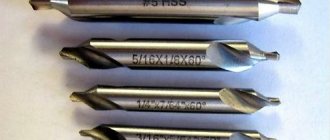
Types of counterbores
The designation of the counterbore in the drawing is given in GOST 26258-87. The same regulatory document defines the technological features of the production of cutting tools and divides them into categories. According to the classification, the following are produced:
- counterbores with cylindrical shanks and guide pins, which are integral with the tool;
- tools with conical shanks and removable trunnions;
- attachment-type products in the form of cutting heads (put on frames with conical shanks, the axle is replaceable);
- tools with replaceable trunnions and shanks, which are mounted in pin locks of machines.
This is interesting: How to harden metal at home: on fire, in oil or in a furnace
Image No. 3: Varieties of counterbores
The working parts of the instruments are manufactured:
- entirely made of high-speed steel;
- with carbide tipped.
Counterbodies for metal have a different number of working blades. Products with cylindrical shanks are equipped with two to four blades. All other varieties - four.
The type of shank affects how exactly the tool is fixed in the machine.
- Counters with cylindrical shanks are installed in chucks.
- Tools with conical shanks are mounted in mounting holes, Morse tapers.
- Products with shanks for fastening in pin locks are used together with machines equipped with these fittings.
Question answer
How to determine the optimal cutting speed?
The cutting speed is selected taking into account the tool diameter and rotation speed. It is necessary to introduce correction factors. The obtained data can be used to calculate the spindle speed.
How to determine the depth of cut with a counterbore?
This indicator is calculated as half the diameter of the cutting tool minus the diameter of the rough hole.
Is it possible to make custom-made counterbores?
Yes, we will produce tools according to your drawings in a period of 5 to 45 days.
A. The center has a lower smooth guide part that is inserted into the hole around which the processing is performed, which makes it possible to maintain the mutual perpendicularity of the resulting surface and the axis of the hole.
Great Soviet Encyclopedia. - M.: Soviet Encyclopedia. 1969-1978. Synonyms
:
See what “Tsevka” is in other dictionaries:
- Countersink for cleaning end surfaces. Typically, counterbores are made in the form of mounted heads with end teeth. Counters are used to process bosses for washers, thrust rings, and nuts. See also: Cutting tools Financial Dictionary... ... Financial Dictionary
Countersinking, countersinking, countersink Dictionary of Russian synonyms. countersink noun, number of synonyms: 4 countersink (2) countersink ... Dictionary of synonyms
counterbore
- NDP. face countersink face countersink trimming Axial multi-edge tool for processing the cylindrical and (or) end section of a workpiece hole. Inadmissible, not recommended trimming... ... Technical Translator's Guide
counterbore
- tsek ovka, and, genus. p.m. h. wok ... Russian spelling dictionary
Countering
— Countersink for cleaning end surfaces (for example, removing bosses). As a rule, it is made in the form of mounted heads with end teeth ... Builder's Dictionary
Countering, processing around the hole of a part to obtain a plane, conical. or cylindrical recesses for a screw head or nut, Dir. special tool countersink (counterbore) ... Big Encyclopedic Polytechnic Dictionary
Countersink, countersink, countersink Dictionary of Russian synonyms. countersink noun, number of synonyms: 2 tool (541) ... Dictionary of synonyms
A production tool for changing the shape and size of a processed metal workpiece by removing part of the material in the form of chips in order to obtain a finished part or semi-finished product. There are machine and manual M. and. Main parts... ...
Treatment of the surface of a part around a hole (a type of countersinking (See countersinking)), intended to form planes or recesses for a screw head, washer, thrust ring, etc. C. is produced on drilling machines, ... ... Great Soviet Encyclopedia
This article should be Wikified. Please format it according to the article formatting rules. Drilling is a type of mechanical processing of materials by cutting, in which using a special rotating cutting tool (drill ... Wikipedia
A counterbore or countersink is a type of metal-cutting tool designed for making cylindrical holes and chamfering holes. Can be used to work on steels, non-ferrous metals, hard alloys.
Washers - guests, designations
Washers are used to protect the surface of the part from damage by the nut when tightening the latter and to increase the bearing area of the nut, bolt head or screw, to eliminate the possibility of the nuts self-unscrewing when they experience vibrations, temperature changes in other cases. There are round washers (Fig. 8.57, a), square (Fig. 8.57, b), spring washers (representing a turn of a screw protrusion in the left direction) (Fig. 8.58), multi-claw (Fig. 8.59), locking, spherical, eliminating pin misalignment or a bolt when changing the position of parts of connected parts (Fig. 8.60), quick-release (Fig. 8.61), oblique (Fig. 8.62) for leveling the slopes of channel flanges and I-beams, etc.
Washers are made by cutting from sheet material (metal, leather, rubber, plastic) or by turning from bar metal, in particular calibrated.
Examples of designations: Washer A.12.01.08kp.016 GOST 11371-78 (Fig. 8.57, a), where version 1 (not indicated), for a fastener with a thread diameter of 12 mm, with a thickness established by the standard, made of steel grade 08kp (indicated for groups 01, 02, 11, 32, since each of them contains two grades of steel); 016 - coating. The same, version 2 (accuracy class A): Washer 2.12.01.08kp. 016 GOST 11371-78. The actual diameter of the hole in the washers is slightly larger than that indicated in the designation by 0.5...2 mm, depending on the thread diameter.
Multi-claw washers are designated similarly (they have one design each): Washer 64.02. StZ.016 GOST 11872-89 (see Fig. 8.59), where 64 is the thread diameter of the round spline nut, 02 is the material group. An example of the designation of a quick-release washer (see Fig. 8.61): Washer 5.03.016 GOST 11648-75, where 5 is the diameter d of the hole, consistent with the diameter d1 of the groove on the shaft. Spring washers (see Fig. 8.58) are produced in four types: light (L), normal (N), heavy (T); especially severe (OT). Example of designation: Washer 12 65G GOST 6402-70, where 12 is the thread diameter of the fastener, 65G is the steel grade (spring manganese). Version 1 is not written, the washer is of normal type (the letter H is not indicated), without coating. An entry in the designation, for example, 12T, will identify a heavy-duty washer. In Fig. 8.58, a - spring washer version 2. Washers of the type shown in Fig. 8.57, b, designate: Washer 6 GOST 24197-80, where b is the diameter of the hole. The material is not specified, since it is provided for by the standard (StZpk according to GOST 380-71**). When using mild steel, the letter C is placed after the hole diameter size, for example 6C. In training drawings it is usually assumed that the washers are not coated. GOST 6402-70* has been supplemented with data on spring washers of version 2.
Scope of application
The counterbore belongs to the same group of tools as the countersink. It is intended to create recesses and improve the quality of the end surfaces of holes in metal products. It is installed mainly on drilling machines, but can also work on turning and milling machines. The tool is a type of counterbore, thereby clarifying the definition of a counterbore and understanding what it is and what it is used for.
The cutting edges of the tool are located at the end of the counterbore working area, along the perimeter of the rotating shaft. At the very end there is a guide pin, which is inserted into the drilled hole, thus aligning its axis with the axis of the tool.
The tasks of the counterbore are as follows:
- obtaining a strictly perpendicular reference plane around the hole for better contact between it and the fastener;
- alignment of the internal end elements of the part;
- removal of burrs and sagging;
- chamfering.
It can be seen that end countersinks provide the dimensional accuracy of metal products required by modern standards and create the conditions necessary for high-quality assembly. And also, if necessary, they process the ends of embedded products.
Getting holes
In order to thoroughly understand what countersinking is, you need to have an idea of how holes are made in parts.
Let's say it is necessary to drill a hole of the fifth accuracy class with a diameter of 12 mm in a workpiece. An important indicator that affects the maximum and minimum values is the required quality. For example, it is necessary to finish countersinking a hole with a diameter of 85 mm with grade H11. Based on the tables of tolerance fields for holes with nominal sizes from 1 to 500 mm, for quality 11 (for diameters from 80 mm to 120 mm) the tolerance field is: the upper value is “+220”, and the lower value is “0”, that is, 85 +220 mm. The maximum diameter of the drilled hole cannot exceed 85.22 mm, and the minimum - 85 mm.
In this case, the size tolerance is the difference between D max and D min, that is, it will be 0.22 mm. If we talk about defects, then for a hole a diameter above the value of 85.22 mm will be considered irreparable, and a diameter less than 85 mm will be considered reparable.
A countersink is a metal-cutting tool with several working blades, designed for processing pre-drilled holes of cylindrical or conical shape. Using a countersink, when choosing the required type of tool, you can obtain recesses of different configurations in the holes of the workpieces. Countersinking should not be confused with countersinking, drilling holes to their full length to improve the quality of the surface.