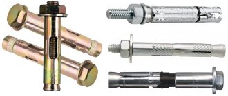
When assembling structures and metal components, threaded connections and rivets are used. Sometimes you need to hide the head of a bolt, screw, or other type of connection. In these cases, the so-called secret is used. That is, at the beginning of the connecting hole, a small depression is made in the metal, where the head is hidden. You can make such a countersink using countersinking - this is a certain type of processing of the beginning of a hole, when it is expanded in diameter and deepened to a certain height. The shape of the recess may vary.
Countersinking should not be confused with countersinking - these are different operations that are performed with different tools. But the equipment that drives such cutters may be the same.
Countersinking can be done using a hand-held electric drill. The difference from the factory version here will be a low level of processing accuracy, but it is quite possible to obtain a countersink at home.
The essence of the countersinking process
Countersinking and drilling are closely related. Typically, countersinking is carried out along a finished hole, but there are cases when it is necessary to make a recess without pre-drilling. In both versions, a countersink tool of different designs is used.
The countersinking process itself is very simple: a special cutter is used to chamfer the hole. The more metal removed, the larger the depression. The countersink shape is usually conical. The main thing here is to maintain strict alignment of the cutting element and the hole: there must be perfect alignment. Otherwise, there will be a displacement of the recess relative to the hole, and the screw head will not be able to fit into it.
To perform a countersinking operation to obtain chamfers and recesses, it is necessary to go through the following process steps:
- Measure the head of the threaded hardware for which the recess will be made (this means both the diameter, height, and bevel angle if the head has a countersunk design).
- Select the appropriate countersink and secure it in the drilling or turning equipment.
- Strictly observing the relationship of the axes, fasten the workpiece with the hole opposite the cutter.
- Turn on the drilling equipment and set the required number of revolutions (if the circuitry of the machine allows it) or deliberately select the necessary tool for the equipment parameters.
- Countersink the hole.
Calculation of the dimensions of blind threaded holes
A blind threaded hole is made in the following order: first, a hole of diameter d1 is drilled for the thread, then a lead-in chamfer Sx45º is made (Fig. 8, a) and, finally, an internal thread d is cut (Fig. 8, b). The bottom of the hole for the thread has a conical shape, and the angle at the apex of the cone φ depends on the sharpening of the drill. When designing, φ = 120º (nominal drill sharpening angle) is assumed. It is quite obvious that the depth of the thread must be greater than the length of the screwed-in threaded end of the fastener. Between the end of the thread and the bottom of the hole there also remains a certain distance a, called “undercut”.
From Fig. 9, the approach to assigning the dimensions of blind threaded holes becomes clear: the thread depth h is defined as the difference between the tightening length L of the threaded part and the total thickness H of the attached parts (there may be one, or there may be several), plus a small thread margin k, usually taken equal 2-3 steps P thread
h = L – H + k,
where k = (2…3) R.
Rice. 8. Sequence of making blind threaded holes
Rice. 9. Screw fastening assembly
The tightening length L of the fastener is indicated in its symbol. For example: “Bolt M6 x 20.46 GOST 7798-70” - its tightening length L = 20 mm. The total thickness of the attached parts H is calculated from the general view drawing (the thickness of the washer placed under the head of the fastener should be added to this amount). The thread pitch P is also indicated in the symbol of the fastener. For example: “Screw M12 x 1.25 x 40.58 GOST 11738-72” - its thread has a fine pitch P = 1.25 mm. If the step is not specified, then by default it is major (large). The lead of the lead-in chamfer S is usually taken equal to the thread pitch P. The depth N of the thread hole is greater than the value h by the undercut size a:
N = h + a.
Some difference in calculating the dimensions of a threaded hole for a stud is that the screwed-in threaded end of the stud does not depend on its tightening length and the thickness of the parts being pulled. For the GOST 22032-76 studs presented in the task, the screwed-in “stud” end is equal to the thread diameter d, therefore
h = d + k.
The resulting dimensions should be rounded to the nearest larger integer.
The final image of a blind threaded hole with the required dimensions is shown in Fig. 10. The diameter of the thread hole and the sharpening angle of the drill are not indicated in the drawing.
Rice. 10. Image of a blind threaded hole in the drawing
The reference tables show the values of all calculated values (diameters of threaded holes, undercuts, washer thicknesses, etc.).
Necessary note: the use of a short undercut must be justified. For example, if the part at the location of the threaded hole in it is not thick enough, and a through hole for the thread can break the tightness of the hydraulic or pneumatic system, then the designer has to “squeeze”, incl. shortening the undercut.
Purpose and features of countersinking
The main area of application of countersinking is in technological processes in the manufacture of machine tools, mechanisms and the assembly of metal structures. Using this operation, the following tasks are achieved:
- In pre-fabricated holes, recesses in the shape of a cylinder or cone are obtained.
- Planes of reference value are formed in the area of the holes.
- Countering the holes allows you to obtain channels with a chamfer removed in them.
- Forming recesses to hide threaded fastener elements.
Countersinking holes has its own characteristics; they are determined by the type of metal that is being processed, the design of the cutter and the final task of the operation:
- If cast iron parts or metals based on hard alloys are being processed, then a special emulsion should be supplied to the work area for cooling.
- The operating speed of the motor shaft must correspond to the operating speed of the countersink. For tools made of high-speed steel, the speed is always lower than for tools with carbide tips.
- To select a countersunk screw head, use a conical cutter with the angle of the end knives equal to the angle of the head cone.
Countersinking is done at the very last stage after countersinking and reaming.
Differences between countersinking and countersinking
Countersinking and countersinking are completely different hole processing operations.
The countersinking process involves the impact on the entire drilled channel. And the purpose of countersinking is to level this hole, to make it better in terms of all geometric parameters and the cleanliness of the channel surface. For countersinking, a special tool (countersink) has been developed, the main knives of which are arranged in a spiral along the entire body of the tool (the length of the body, as a rule, exceeds the length of the hole channel). The countersink only works on part of the hole at the beginning. Its main task is to make a countersunk or chamfer. Therefore, the tool mainly has knives at the end. The only thing that a countersink and a countersink have in common is that they are driven using the same machines.
Equipment and tools
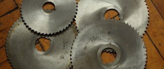
The main tool used for countersinking is called a countersink. This is a type of cutter consisting of a working part and a shank. The working part has several cutting edges; the tool is attached to the shank in the equipment chuck. There are conical and cylindrical cutters. The raw material for the manufacture of countersinks is carbon or alloy tool steel.
Conical countersinks are characterized by the angle of inclination of the knife. The most commonly used elements are those with cone angles of 120, 90, 60 and 30 degrees. Cylindrical cutters have teeth at the end. These teeth can be from 8 to 4 pieces. In addition, the cylindrical tool has an element guiding the hole, which is called a pin. Thanks to this element, the cylindrical cutter is always aligned with the hole it is processing.
For countersinking holes, special holders have also been developed into which countersinks are inserted. They may have rotating or non-rotating type limiters.
VIEW Countersinking cutters on AliExpress →
Types of Hole Making Tools
Both the countersink and the countersink, in terms of their geometric parameters, must comply with the requirements indicated by the corresponding GOST or Technical Specifications (TU). The working part of the countersink consists of many cutting blades. It is used to process holes previously obtained by drilling. Depending on the design and scope of application, the following types of countersinks are distinguished.
- Cylindrical tools, the working part of which is coated with a wear-resistant material. Countersinks of this type, the requirements for which are regulated by GOST 12489-71, are produced with diameters from 10 to 20 mm.
- Solid countersinks of conical type, produced in the diameter range of 10–40 mm. The material for the manufacture of these tools, the characteristics of which must meet the requirements of TU 2-035-923-83, can be alloyed high-speed steel, as well as tool steel alloys. At the same time, a wear-resistant coating is applied to the working surface of such a countersink. Tools belonging to this category can be used for machining holes made in steel and cast iron parts.
- Countersinks are of one-piece mounted type, the diameter of which can be in the range of 32–80 mm. They are manufactured in accordance with the requirements established by GOST 12489-71.
- Conical countersinks, which can be of two types: type 1, produced in accordance with GOST 3231-71, and type 2 - a mounted countersink, the requirements for the characteristics of which are regulated by the provisions of the same regulatory document. The two types of countersinks differ only in the presence of plates on their working part, which are made of carbide material.
Countersink with guide pin
A countersink also belongs to the category of multi-blade cutting tools, but it is distinguished from a countersink by a list of technological tasks that can be solved with its help. In particular, using it, you can make recesses in pre-made holes, form chamfers on their surface, etc. The following types of countersinks are distinguished depending on their design.
- Conical countersinks, the working surface of which can be manufactured with angles of 60, 90 and 120°. The production of such countersinks is regulated by GOST 14953-80E, and they are used for processing holes for fasteners, metal products, as well as for removing internal chamfers.
- Countersinks are cylindrical type, which can be produced with a conical or cylindrical shank, as well as with a wear-resistant coating on the working surface. The regulatory document, the provisions of which regulate the requirements for the characteristics of cylindrical countersinks, is GOST 2I22-2-80. Using such a tool, support-type surfaces are usually processed.
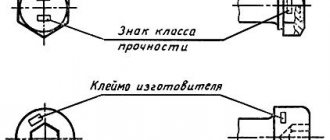
Countersink designation in the drawing
In production, countersinking of holes is carried out according to the drawing. The countersink in the drawing is displayed in uppercase and capital Latin letters and Arabic numerals. The meaning of the letters and numbers is as follows:
- d1 – indicates the main diameter of the channel;
- d2 – for countersinking diameter;
- L1 – displays the length of the cylindrical channel;
- L3 is the countersinking depth;
- L4 – indicates the depth of the chamfer;
- j is the size of the central countersinking angle;
- α (alpha) – chamfer angle size.
Dear site visitors: mechanical engineers, craftsmen and those simply familiar with the topic, support the discussion in the comments! Your professional comments are very important to us.
Geodetic control during pit construction
When laying out the plan and height of the pit, its outline is drawn out onto the ground according to the drawing, which shows the dimensions of the pit along the top edge and bottom, the plan of the foundations and the marks of its base (depth).
The lines of zero work (the upper edge of the pit) are marked with stakes or marks on the cast-off. In the process of digging a pit, the current depth of the excavation is determined and it is ensured that there is no depression below the design mark of its bottom. The lower contour of the pit must correspond to the design outlines and dimensions. During the excavation process, the depth of the pit is systematically monitored using permanent sights attached to the cast-off and portable (walking) sights. At
Digging a pit and removing soil is not allowed.
When constructing deep and significant pits, temporary benchmarks are installed at their bottom and on ledges. The mark on the bottom of such pits is transferred according to the scheme presented in Fig. 8.
Fig.8. Transferring the mark to the bottom of the pit
From the figure it can be seen that the marks of points C and D will be
Нс = HA + a – (b+d),
НD = HA + a – (l + ƒ),
where a, d, ƒ – readings from the slats installed at points A, C and D,
l and b – tape counts.
To control, marks are transferred to the bottom of the pit from two working benchmarks with a change in the position of the tape measure suspension.
In practice, the mark on the bottom of the pit is transmitted with an accuracy of ± 1 cm.