GOST 3262-75
INTERSTATE STANDARD
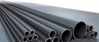
STEEL WATER AND GAS PIPES
TECHNICAL CONDITIONS
| Moscow Standardinform 2007 |
INTERSTATE STANDARD
| STEEL WATER AND GAS PIPES Specifications Water-supply and gas-supply steel pipes Technical conditions | GOST 3262-75 |
Date of introduction 01/01/77
This standard applies to non-galvanized and galvanized steel welded pipes with cut or rolled cylindrical threads and without threads, used for water and gas pipelines, heating systems, as well as for parts of water and gas pipeline structures.
(Changed edition, Amendment No. 2, 3, 5).
TECHNICAL REQUIREMENTS
2.1. Pipes are manufactured in accordance with the requirements of this standard and according to technological regulations approved in the prescribed manner, from steels in accordance with GOST 380 and GOST 1050 without standardization of mechanical properties and chemical composition.
Pipes for parts of water supply and gas pipeline structures are made of steel in accordance with GOST 1050.
2.2. At the request of the consumer, the ends of pipes to be welded, with a wall thickness of 5 mm or more, must be chamfered at an angle of 35 - 40° to the end of the pipe. In this case, an end ring 1 - 3 mm wide should be left.
At the request of the consumer, on ordinary and reinforced pipes with a nominal bore of more than 10 mm, threads are applied to both ends of the pipe.
2.1; 2.2. (Changed edition, Amendment No. 3, 4).
2.3. At the request of the consumer, pipes are equipped with couplings manufactured in accordance with GOST 8944, GOST 8954, GOST 8965 and GOST 8966 at the rate of one coupling for each pipe.
(Changed edition, Amendment No. 3).
2.4. Cracks, spots, swellings and declines are not allowed on the surface of the pipes.
Delamination is not allowed at the ends of the pipes.
Individual dents, rippling, scratches, traces of stripping and other defects caused by the production method are allowed, if they do not take the wall thickness beyond the minimum dimensions, as well as a layer of scale that does not interfere with inspection.
On pipes made by furnace welding, it is allowed to reduce the outer diameter to 0.5 mm at the seam if there is a gentle thickening in this place along the inner diameter of no more than 1.0 mm.
(Changed edition, Amendment No. 3, 4).
2.5. At the request of the consumer, on pipes with a nominal bore of 20 mm or more, the burr on the inner surface of the pipe seam must be cut off or flattened, and the height of the burr or its traces should not exceed 0.5 mm.
At the request of the consumer, on pipes with a nominal bore of more than 15 mm, manufactured by furnace welding and hot reduction, a gentle thickening with a height of no more than 0.5 mm is allowed on the inner surface of the pipes in the weld area.
(Changed edition, Amendment No. 2, 3, 4, 5, 6).
2.6. The ends of the pipes must be cut at right angles. The bevel of the end is allowed to be no more than 2°. The remaining burrs should not exceed 0.5 mm. When removing burrs, the formation of blunting (rounding) of the ends is allowed. It is allowed to cut pipes in the mill line.
By agreement between the manufacturer and the consumer, burrs up to 1 mm are allowed on pipes with a nominal bore of 6 - 25 mm, manufactured by furnace welding.
(Changed edition, Amendment No. 4, 6).
2.7. Galvanized pipes must have a continuous zinc coating over the entire surface with a thickness of at least 30 microns. The absence of zinc coating on the ends and threads of pipes is allowed.
On the surface of galvanized pipes, bubbles and foreign inclusions (hardzinc, oxides, sintered mixture), and peeling of the coating from the base metal are not allowed.
Individual flux spots and traces of pipes being caught by lifting devices, roughness and minor local deposits of zinc are allowed.
It is allowed to correct individual non-galvanized areas on 0.5% of the outer surface of the pipe in accordance with GOST 9.307.
(Changed edition, Amendment No. 3, 4).
2.8. Pipes must withstand hydraulic pressure:
2.4 MPa (25 kgf/cm2) - pipes, ordinary and light;
3.1 MPa (32 kgf/cm2) - reinforced pipes.
At the request of the consumer, the pipes must withstand hydraulic pressure of 4.9 MPa (50 kgf/cm2)
(Changed edition, Amendment No. 2, 3, 5).
2.9. Pipes with a nominal bore up to 40 mm inclusive must withstand the bend test around a mandrel with a radius equal to 2.5 outer diameters, and with a nominal bore of 50 mm - on a mandrel with a radius equal to 3.5 outer diameters.
At the request of the consumer, pipes must withstand the distribution test:
for pipes with a nominal bore from 15 to 50 mm - no less than 7%;
for pipes with a nominal bore of 65 or more - no less than 4%.
At the request of the consumer, pipes must withstand the flattening test to a distance between the flattened surfaces equal to 2/3 of the outer diameter of the pipes.
(Changed edition, Amendment No. 2, 3, 5).
2.10. At the request of the consumer, the mechanical properties of pipes for parts of water supply and gas pipeline structures must comply with GOST 1050.
2.11. Pipe threads must be clean, without flaws or burrs and comply with GOST 6357, accuracy class B.
Pipes with cylindrical threads are used when assembling with seals.
2.10; 2.11. (Changed edition, Amendment No. 3, 4).
2.12. At the seam, blackness on the threads is allowed if the reduction in the normal height of the thread profile does not exceed 15%, and at the request of the consumer does not exceed 10%.
Threads with torn (for cut) or incomplete (for rolled) threads are allowed on threads, provided that their total length does not exceed 10% of the required thread length, and at the request of the consumer does not exceed 5%.
(Changed edition, Amendment No. 2, 3, 5).
2.13. On a thread, it is allowed to reduce the useful length of the thread (without running) up to 15% compared to that indicated in the table. 4, and at the consumer’s request up to 10%.
(Changed edition, Amendment No. 2, 3, 5).
2.14. Threading on galvanized pipes is carried out after galvanizing.
2.15. (Deleted, Amendment No. 3).
2.16. At the request of the consumer, pipe welds are subjected to testing using non-destructive methods.
(Changed edition, Amendment No. 5).
GOST 3262-75: Steel water and gas pipes
Home / GOSTs / GOST 3262-75: Steel water and gas pipes
GOST 3262-75: Steel water and gas pipes
GOST 3262-75
Steel water and gas pipes
Specifications
This standard applies to non-galvanized and galvanized steel welded pipes with cut or rolled cylindrical threads and without threads, used for water and gas pipelines, heating systems, as well as for parts of water and gas pipeline structures.
(Changed edition, Amendment No. 2, 3, 5).
1. Assortment
1.1. Pipes are manufactured according to the dimensions and weight given in table. 1.
At the consumer's request, light series pipes intended for thread rolling are manufactured according to the dimensions and weight given in table. 2.
1.2. The length of the pipe is made from 4 to 12 m:
a) measured or multiple measured length with an allowance for each cut of 5 mm and a longitudinal deviation over the entire length plus 10 mm;
b) of unmeasured length.
By agreement between the manufacturer and the consumer, up to 5% of pipes with a length of 1.5 to 4 m are allowed in a batch of unmeasured pipes.
(Changed edition, Amendment No. 3, 4).
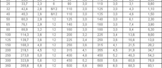
Table 1, mm
| Conditional pass | Outside diameter | Pipe wall thickness | Weight of 1 m of pipes, kg | ||||
| lungs | ordinary | reinforced | lungs | ordinary | reinforced | ||
| 6 | 10,2 | 1,8 | 2,0 | 2,5 | 0,37 | 0,40 | 0,47 |
| 8 | 13,5 | 2,0 | 2,2 | 2,8 | 0,57 | 0,61 | 0,74 |
| 10 | 17,0 | 2,0 | 2,2 | 2,8 | 0,74 | 0,80 | 0,98 |
| 15 | 21,3 | 2,35 | — | — | 1,10 | — | — |
| 15 | 21,3 | 2,5 | 2,8 | 3,2 | 1,16 | 1,28 | 1,43 |
| 20 | 26,8 | 2,35 | — | — | 1,42 | — | — |
| 20 | 26,8 | 2,5 | 2,8 | 3,2 | 1,50 | 1,66 | 1,86 |
| 25 | 33,5 | 2,8 | 3,2 | 4,0 | 2,12 | 2,39 | 2,91 |
| 32 | 42,3 | 2,8 | 3,2 | 4,0 | 2,73 | 3,09 | 3,78 |
| 40 | 48,0 | 3,0 | 3,5 | 4,0 | 3,33 | 3,84 | 4,34 |
| 50 | 60,0 | 3,0 | 3,5 | 4,5 | 4,22 | 4,88 | 6,16 |
| 65 | 75,5 | 3,2 | 4,0 | 4,5 | 5,71 | 7,05 | 7,88 |
| 80 | 88,5 | 3,5 | 4,0 | 4,5 | 7,34 | 8,34 | 9,32 |
| 90 | 101,3 | 3,5 | 4,0 | 4,5 | 8,44 | 9,60 | 10,74 |
| 100 | 114,0 | 4,0 | 4,5 | 5,0 | 10,85 | 12,15 | 13,44 |
| 125 | 140,0 | 4,0 | 4,5 | 5,5 | 13,42 | 15,04 | 18,24 |
| 150 | 165,0 | 4,0 | 4,5 | 5,5 | 15,88 | 17,81 | 21,63 |
Table 2, mm
| Conditional pass | Outside diameter | Wall thickness | Weight of 1 m of pipes, kg |
| 10 | 16 | 0,2 | 0,69 |
| 15 | 20 | 2,5 | 1,08 |
| 20 | 26 | 2,5 | 1,45 |
| 25 | 32 | 2,8 | 2,02 |
| 32 | 41 | 2,8 | 2,64 |
| 40 | 47 | 3,0 | 3,26 |
| 50 | 59 | 3,0 | 4,14 |
| 65 | 74 | 3,2 | 5,59 |
Notes:
1. For threads made by rolling on a pipe, its internal diameter is allowed to be reduced by up to 10% along the entire length of the thread.
2. The mass of 1 m of pipes is calculated at a steel density of 7.85 g/cm. Galvanized pipes are 3% heavier than non-galvanized ones.
(Changed edition, Amendment No. 1, 3).
1.3. Maximum deviations in pipe sizes should not exceed those indicated in the table. 3.
Table 3
| Pipe size | Maximum deviation for manufacturing | |
| ordinary | increased | |
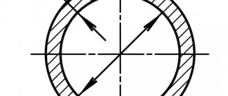
| Outer diameter with nominal bore: | ||
| up to 40 mm incl. | + 0.4 mm - 0.5 | ±0.4mm |
| over 40 mm | + 0,8 % — 1,0 | ± 0,8 % |
| Wall thickness | — 15 % | — 10 % |
Notes:
1. The maximum deviation in the positive direction for wall thickness is limited by the maximum deviations for the mass of the pipes.
2. Pipes of standard manufacturing precision are used for water supply, gas pipelines and heating systems. Pipes with increased manufacturing precision are used for parts of water and gas pipeline structures.
(Changed edition, Amendment No. 3).
1.4. Maximum deviations in the mass of pipes should not exceed + 8%.
At the request of the consumer, maximum deviations in mass should not exceed:
- +7.5% - for the party;
- +10% - for a separate pipe.
(Changed edition, Amendment No. 2, 5).
1.5. The curvature of pipes per 1 m length should not exceed:
- 2 mm - with nominal bore up to 20 mm inclusive;
- 1.5 mm - with a nominal bore over 20 mm.
1.6. Pipe threads can be long or short. The thread requirements must correspond to those indicated in the table. 4.
1.7. Pipes with a nominal diameter of 6, 8, 10, 15 and 20 mm are wound into coils at the consumer’s request.
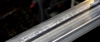
Examples of symbols
An ordinary pipe, non-galvanized, of normal manufacturing precision, of unmeasured length, with a nominal bore of 20 mm, a wall thickness of 2.8 mm, without threads and without a coupling:
Pipe 20x2.8 GOST 3262-75
Table 4
| Conditional bore, mm | Number of threads at nominal size | Thread length before run-out, mm | |
| long | short | ||
| 6 | — | — | — |
| 8 | — | — | — |
| 10 | — | — | — |
| 15 | 14 | 14 | 9,0 |
| 20 | 14 | 16 | 10,5 |
| 25 | 11 | 18 | 11,0 |
| 32 | 11 | 20 | 13,0 |
| 40 | 11 | 22 | 15,0 |
| 50 | 11 | 24 | 17,0 |
| 65 | 11 | 27 | 19,5 |
| 80 | 11 | 30 | 22,0 |
| 90 | 11 | 33 | 26,0 |
| 100 | 11 | 36 | 30,0 |
| 125 | 11 | 38 | 33,0 |
| 150 | 11 | 42 | 36,0 |
The same with the coupling:
Pipe M-20x2.8 GOST 3262-75
The same, measured length, with thread:
Pipe P-20x2.8-4000 GOST 3262-75
The same, with zinc coating, of unmeasured length, with thread:
Pipe Ts-R-20x2.8 GOST 3262-75
The same, with zinc coating, custom length, with thread:
Pipe Ts-R-20x2.8-4000 GOST 3262-75
For pipes for rolling threads, the letter N is indicated in the symbol after the word “pipe”.
For pipes with long threads, the letter D is indicated after the word “pipe” in the symbol.
For pipes with increased manufacturing precision, the letter P is indicated in the symbol after the size of the nominal bore.
(Changed edition, Amendment No. 1).
2. Technical requirements
2.1. Pipes are manufactured in accordance with the requirements of this standard and according to technological regulations approved in the prescribed manner, from steels in accordance with GOST 380 and GOST 1050 without standardization of mechanical properties and chemical composition.
Pipes for parts of water supply and gas pipeline structures are made of steel in accordance with GOST 1050.
2.2. At the request of the consumer, the ends of pipes to be welded, with a wall thickness of 5 mm or more, must be chamfered at an angle of 35-40 ° to the end of the pipe. In this case, an end ring 1-3 mm wide should be left.
At the request of the consumer, on ordinary and reinforced pipes with a nominal bore of more than 10 mm, threads are applied to both ends of the pipe.
2.1; 2.2. (Changed edition, Amendment No. 3, 4).
2.3. At the request of the consumer, pipes are equipped with couplings manufactured in accordance with GOST 8944, GOST 8954, GOST 8965 and GOST 8966, at the rate of one coupling for each pipe.
(Changed edition, Amendment No. 3).
2.4. Cracks, spots, swellings and declines are not allowed on the surface of the pipes.
Delamination is not allowed at the ends of the pipes.
Individual dents, rippling, scratches, traces of stripping and other defects caused by the production method are allowed, if they do not take the wall thickness beyond the minimum dimensions, as well as a layer of scale that does not interfere with inspection.
On pipes made by furnace welding, it is allowed to reduce the outer diameter to 0.5 mm at the seam if there is a gentle thickening in this place along the inner diameter of no more than 1.0 mm.
(Changed edition, Amendment No. 3, 4).
2.5. At the request of the consumer, on pipes with a nominal bore of 20 mm or more, the burr on the inner surface of the pipe seam must be cut off or flattened, and the height of the burr or its traces should not exceed 0.5 mm.
At the request of the consumer, on pipes with a nominal bore of more than 15 mm, manufactured by furnace welding and hot reduction, a gentle thickening with a height of no more than 0.5 mm is allowed on the inner surface of the pipes in the weld area.
(Changed edition, Amendment No. 2, 3, 4, 5, 6).
2.6. The ends of the pipes must be cut at right angles. The bevel of the end is allowed to be no more than 2°. The remaining burrs should not exceed 0.5 mm. When removing burrs, the formation of blunting (rounding) of the ends is allowed. It is allowed to cut pipes in the mill line.
By agreement between the manufacturer and the consumer, burrs up to 1 mm are allowed on pipes with a nominal bore of 6-25 mm, manufactured by furnace welding.
(Changed edition, Amendment No. 4, 6).
2.7. Galvanized pipes must have a continuous zinc coating over the entire surface with a thickness of at least 30 microns. The absence of zinc coating on the ends and threads of pipes is allowed.
On the surface of galvanized pipes, bubbles and foreign inclusions (hardzinc, oxides, sintered mixture), and peeling of the coating from the base metal are not allowed.
Individual flux spots and traces of pipes being caught by lifting devices, roughness and minor local deposits of zinc are allowed.
It is allowed to correct individual non-galvanized areas on 0.5% of the outer surface of the pipe in accordance with GOST 9.307.
(Changed edition, Amendment No. 3, 4).
2.8. Pipes must withstand hydraulic pressure:
2.4 MPa (25 kgf/cm) - ordinary and light pipes;
3.1 MPa (32 kgf/cm) - reinforced pipes.
At the request of the consumer, the pipes must withstand a hydraulic pressure of 4.9 MPa (50 kgf/cm).
(Changed edition, Amendment No. 2, 3, 5).
2.9. Pipes with a nominal bore up to 40 mm inclusive must withstand the bend test around a mandrel with a radius equal to 2.5 outer diameters, and with a nominal bore of 50 mm - on a mandrel with a radius equal to 3.5 outer diameters.
At the request of the consumer, pipes must withstand the distribution test:
- for pipes with a nominal bore from 15 to 50 mm - no less than 7%;
- for pipes with a nominal bore of 65 mm or more - no less than 4%.
At the request of the consumer, pipes must withstand the flattening test to a distance between flattened surfaces equal to 2/3 of the outer diameter of the pipes.
(Changed edition, Amendment No. 2, 3, 5).
2.10. At the request of the consumer, the mechanical properties of pipes for parts of water supply and gas pipeline structures must comply with GOST 1050.
2.11. Pipe threads must be clean, without flaws or burrs and comply with GOST 6357, accuracy class B.
Pipes with cylindrical threads are used when assembling with seals.
2.10; 2.11. (Changed edition, Amendment No. 3, 4).
2.12. At the seam, blackness on the threads is allowed if the reduction in the normal height of the thread profile does not exceed 15%, and at the request of the consumer does not exceed 10%.
Threads with torn (for cut) or incomplete (for rolled) threads are allowed on threads, provided that their total length does not exceed 10% of the required thread length, and at the request of the consumer does not exceed 5%.
(Changed edition, Amendment No. 2, 3, 5).
2.13. On a thread, it is allowed to reduce the useful length of the thread (without running) up to 15% compared to that indicated in the table. 4, and at the consumer’s request - up to 10%.
(Changed edition, Amendment No. 2, 3, 5).
2.14. Threading on galvanized pipes is carried out after galvanizing.
2.15. (Deleted, Amendment No. 3).
2.16. At the request of the consumer, pipe welds are subjected to testing using non-destructive methods.
(Changed edition, Amendment No. 5).
3. Acceptance rules
3.1. Pipes are accepted in batches. The batch must consist of pipes of the same size, the same grade of steel and be accompanied by one quality document in accordance with GOST 10692 with an addition for pipes intended for the manufacture of parts for water supply and gas structures, made of steel in accordance with GOST 1050; chemical composition and mechanical properties of steel - in accordance with the document on the quality of the manufacturer of the workpiece.
Lot weight: no more than 60 tons.
(Changed edition, Amendment No. 3, 4).
3.2. Each pipe in the batch is subjected to inspection of the surface, dimensions and curvature.
It is allowed to use statistical control methods in accordance with GOST 18242 with a normal level. Control plans are established by agreement between the manufacturer and the consumer.
The outer diameter of the pipes is checked at a distance of at least 15 mm from the end of the pipe.
(Changed edition, Amendment No. 3, 4, 5).
3.3. To control the parameters of the thread, to test for expansion, flattening, bending, the height of the internal burr, the remains of burrs, the right angle and the chamfer angle (for pipes with beveled edges), mechanical properties, no more than 1%, but not less than two pipes from the batch are selected, and for pipes manufactured by continuous furnace welding - two pipes per batch.
(Changed edition, Amendment No. 3, 4).
3.4. All pipes are subject to weight control.
(Changed edition, Amendment No. 3).
3.5. Each pipe is subjected to hydraulic pressure testing. With 100% quality control of the weld using non-destructive methods, hydraulic pressure testing may not be carried out. At the same time, the ability of the pipes to withstand the test hydraulic pressure is guaranteed.
(Changed edition, Amendment No. 6).
3.6. To check the thickness of the zinc coating on the outer surface and in accessible places on the inner surface, two pipes from the batch are selected.
(Changed edition, Amendment No. 2).
3.7. If unsatisfactory test results are obtained for at least one of the indicators, repeated tests are carried out on a double sample.
The results of repeated tests apply to the entire batch.
4. Test methods
4.1. For quality control, one sample is cut from each selected pipe for each type of test.
The tensile test is carried out in accordance with GOST 10006. Instead of the tensile test, it is allowed to control the mechanical properties by non-destructive methods.
(Changed edition, Amendment No. 3, 6).
4.2. Inspection of the pipe surface is carried out visually.
4.3. Hydraulic testing is carried out in accordance with GOST 3845 with exposure to test pressure for at least 5 s.
4.4. The bend test is carried out according to GOST 3728. Galvanized pipes are tested before coating.
(Changed edition, Amendment No. 3).
4.4a. The expansion test is carried out according to GOST 8694 on a conical mandrel with a cone angle of 6°.
Testing on a mandrel with a taper angle of 30° is allowed.
(Changed edition, Amendment No. 3, 4).
4.4b. The flattening test is carried out according to GOST 8695.
(Changed edition, Amendment No. 3).
4.4v. Weld inspection is carried out using non-destructive methods according to regulatory and technical documentation.
(Introduced additionally, Amendment No. 3).
4.5. The thickness of the zinc coating on the outer surface and in accessible places on the inner surface is controlled according to GOST 9.301 and GOST 9.302, as well as with devices of the MT-41NTs, MTZON or Impulse type according to the normative and technical documentation.
4.6. The thread is checked using thread ring gauges in accordance with GOST 2533 (third accuracy class).
In this case, the screw-in of the no-go ring gauge onto the thread should be no more than three turns.
(Changed edition, Amendment No. 3, 4).
4.7. The curvature of the pipes is controlled using a straight edge in accordance with GOST 8026 and a set of probes in accordance with TU 2-034-225.
(Changed edition, Amendment No. 3, 5).
4.8. The right angle of the pipe ends is controlled with a 90° square measuring 160x100 mm, class 3 GOST 3749, plate probes set 4 TU 2-034-225 or an inclinometer, GOST 5378. The bevel angle is controlled with an inclinometer in accordance with GOST 5378.
(Changed edition, Amendment No. 3, 6).
4.9. The outer diameter is checked using smooth micrometers in accordance with GOST 6507, clamp gauges in accordance with GOST 2216 or GOST 18360.
The wall thickness, the height of the internal burr and the height of the burrs are measured with a micrometer according to GOST 6507 or a wall gauge according to GOST 11358 from both ends of the pipe
The length of the pipes is measured with a tape measure in accordance with GOST 7502. The threads are controlled with gauges in accordance with GOST 2533.
The mass of a batch of pipes is controlled on scales of no more than 10 tons with a division value of no more than 20 kg.
(Changed edition, Amendment No. 3, 4, 5, 6).
4.10. Weld inspection is carried out using non-destructive methods according to technical documentation.
(Introduced additionally, Amendment No. 4).
5. Labeling, packaging, transportation
5.1. Labeling, packaging, transportation and storage are carried out in accordance with GOST 10692 with addition.
5.1.1. Pipe threads must be protected from mechanical damage and corrosion by lubricant according to the regulatory and technical documentation.
Sec.
5. (Changed edition, Amendment No. 3). and storage
ACCEPTANCE RULES
3.1. Pipes are accepted in batches. The batch must consist of pipes of the same size, the same grade and be accompanied by one quality document in accordance with GOST 10692 with an addition for pipes intended for the manufacture of parts for water supply and gas pipeline structures, made of steel in accordance with GOST 1050: chemical composition and mechanical properties of steel in accordance with document on the quality of the workpiece manufacturer.
The batch weight is no more than 60 tons.
(Changed edition, Amendment No. 3, 4).
3.2. Each pipe in the batch is subjected to inspection of the surface, dimensions and curvature.
It is allowed to use statistical control methods in accordance with GOST 18242* with a normal level. Control plans are established by agreement between the manufacturer and the consumer.
___________
* GOST R 50779.71-99 is in force on the territory of the Russian Federation.
The outer diameter of the pipes is checked at a distance of at least 15 mm from the end of the pipe.
(Changed edition, Amendment No. 3, 4, 5).
3.3. To control the parameters of the thread, to test for expansion, flattening, bending, the height of the internal burr, the remains of burrs, the right angle and the chamfer angle (for pipes with beveled edges), mechanical properties, no more than 1%, but not less than two pipes from the batch are selected, and for pipes manufactured by continuous furnace welding - two pipes per batch.
(Changed edition, Amendment No. 3, 4).
3.4. All pipes are subject to weight control.
(Changed edition, Amendment No. 3).
3.5. Each pipe is subjected to hydraulic pressure testing. With 100% quality control of the weld using non-destructive methods, hydraulic pressure testing may not be carried out. At the same time, the ability of the pipes to withstand the test hydraulic pressure is guaranteed.
(Changed edition, Amendment No. 6).
3.6. To check the thickness of the zinc coating on the outer surface and in accessible places on the inner surface, two pipes from the batch are selected.
(Changed edition, Amendment No. 2).
3.7. If unsatisfactory test results are obtained for at least one of the indicators, a repeat test is carried out on a double sample.
The results of repeated tests apply to the entire batch.
TEST METHODS
4.1. For quality control, one sample is cut from each selected pipe for each type of test.
The tensile test is carried out in accordance with GOST 10006. Instead of the tensile test, it is allowed to control the mechanical properties by non-destructive methods.
(Changed edition, Amendment No. 3, 6).
4.2. The surface of the pipes is inspected visually.
4.3. Hydraulic testing is carried out in accordance with GOST 3845 with exposure to test pressure for at least 5 s.
4.4. The bend test is carried out according to GOST 3728. Galvanized pipes are tested before coating.
(Changed edition, Amendment No. 3).
4.4a. The expansion test is carried out according to GOST 8694 on a conical mandrel with a cone angle of 6°.
Testing on a mandrel with a taper angle of 30° is allowed.
(Changed edition, Amendment No. 3, 4).
4.4b. The flattening test is carried out according to GOST 8695.
(Changed edition, Amendment No. 3).
4.4v. Weld inspection is carried out using non-destructive methods according to regulatory and technical documentation.
(Introduced
additionally, Amendment No. 3 ).
4.5. The thickness of the zinc coating on the outer surface and in accessible places on the inner surface is controlled according to GOST 9.301 and GOST 9.302, as well as with devices of the MT-41NTs, MTZON or Impulse type according to the normative and technical documentation.
4.6. The thread is checked using thread ring gauges in accordance with GOST 2533 (third accuracy class).
In this case, the screw-in of the no-go ring gauge onto the thread should be no more than three turns.
(Changed edition, Amendment No. 3, 4).
4.7. The curvature of the pipes is controlled using a straight edge in accordance with GOST 8026 and a set of probes in accordance with NTD.
(Changed edition, Amendment No. 3, 5).
4.8. The right angle of the pipe ends is controlled with a 90° square measuring 160´100 mm, class 3 GOST 3749, plate probes set 4 according to NTD or an inclinometer GOST 5378. The bevel angle of the chamfer is controlled with an inclinometer according to GOST 5378.
(Changed edition, Amendment No. 3, 6).
4.9. The outer diameter is checked using smooth micrometers in accordance with GOST 6507, clamp gauges in accordance with GOST 2216 or GOST 18360.
The wall thickness, the height of the internal burr and the height of the burrs are measured with a micrometer according to GOST 6507 or a wall gauge according to GOST 11358 at both ends of the pipe.
The length of the pipes is measured with a tape measure in accordance with GOST 7502. The threads are controlled with gauges in accordance with GOST 2533.
The mass of a batch of pipes is controlled on scales of no more than 10 tons with a division value of no more than 20 kg.
(Changed edition, Amendment No. 3, 4, 5, 6).
4.10. Weld inspection is carried out using non-destructive methods according to technical documentation.
(Introduced
additionally, Amendment No. 4 ).
Scope of application of VGP pipes
The most common area of use of water and gas pipes is housing and communal services. In second place is the private sector, that is, construction companies and LLCs.
In addition, VGP pipes are also used in non-trivial ways - for example, to create metal structures used in small and large architectural forms.
The GOST Metal company offers to buy VGP pipes in Moscow at competitive prices; these products are available in our warehouses at the GOST Metal company. We will provide our customers with quality products, affordable prices and timely delivery.