Inch threads are used primarily to create pipe connections: they are applied both to the pipes themselves and to metal and plastic fittings necessary for the installation of pipe lines for various purposes. The main parameters and characteristics of the threaded elements of such connections are regulated by the corresponding GOST, providing tables of inch thread sizes, which experts rely on.
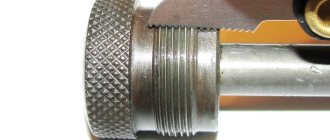
Plumbing products with inch pipe threads
Main settings
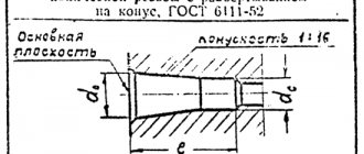
The regulatory document that stipulates the requirements for the dimensions of cylindrical inch threads is GOST 6111-52. Like any other, inch thread is characterized by two main parameters: pitch and diameter. The latter usually means:
- outer diameter, measured between the top points of the threaded ridges located on opposite sides of the pipe;
- internal diameter as a value characterizing the distance from one lowest point of the cavity between the threaded ridges to another, also located on opposite sides of the pipe.
Inch thread parameters
Knowing the outer and inner diameters of an inch thread, you can easily calculate the height of its profile. To calculate this size, it is enough to determine the difference between these diameters.
The second important parameter - the pitch - characterizes the distance at which two adjacent ridges or two adjacent depressions are located from each other. Throughout the entire section of the product on which the pipe thread is made, its pitch does not change and has the same value. If such an important requirement is not met, it will simply not work; it will not be possible to select a second element of the connection being created for it.
You can familiarize yourself with the provisions of GOST regarding inch threads by downloading the document in pdf format from the link below.
GOST 6111-52 Conical inch thread with a profile angle of 60°
Use nuts and bolts of the same strength and material
An important factor that affects the reliability and durability of the connection is the compatibility of bolts and nuts in terms of strength and material. The nut's load resistance should be equal to or even stronger than the bolt. That is, a stronger nut can be used with a weaker bolt, but not vice versa. For example, a grade 8 nut is acceptable for use with a grade 5 and grade 8 bolt.
Differences from metric threads
In terms of their external features and characteristics, metric and inch threads do not have many differences, the most significant of which include:
- profile shape of the threaded ridge;
- procedure for calculating diameter and pitch.
Differences in thread profile
When comparing the shapes of threaded ridges, you can see that in inch threads such elements are sharper than in metric threads. If we talk about exact dimensions, the angle at the top of the ridge of an inch thread is 55°.
The parameters of metric and inch threads are characterized by different units of measurement. So, the diameter and pitch of the former are measured in millimeters, and the latter, respectively, in inches. It should, however, be borne in mind that in relation to an inch thread, it is not the generally accepted one (2.54 cm), but a special pipe inch equal to 3.324 cm that is used. Thus, if, for example, its diameter is ¾ inch, then in terms of millimeters it will correspond to the value 25.
To find out the basic parameters of an inch thread of any standard size, which is fixed by GOST, just look at the special table. The tables containing inch thread sizes contain both whole and fractional values. It should be borne in mind that the pitch in such tables is given in the number of cut grooves (threads) contained in one inch of product length.
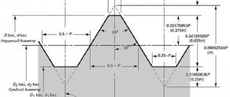
Drawing. Main profile parameters according to GOST
Table 1. Main thread profile dimensions
Table 2. Basic parameters of pipe threads
To check whether the pitch of the thread already made corresponds to the dimensions specified by GOST, this parameter must be measured. For such measurements, carried out for both metric and inch threads using the same algorithm, standard tools are used - a comb, a gauge, a mechanical gauge, etc.
The easiest way to measure the pitch of an inch pipe thread is using the following method:
- As a simple template, a coupling or fitting is used, the internal thread parameters of which exactly correspond to the requirements given by GOST.
- The bolt, the external thread parameters of which need to be measured, is screwed into the coupling or fitting.
- If the bolt has formed a tight threaded connection with the coupling or fitting, then the diameter and pitch of the thread that is applied to its surface exactly correspond to the parameters of the template used.
Inch thread pitch is the number of threads per inch
If the bolt does not screw into the template or screws in but creates a loose connection with it, then such measurements should be carried out using another coupling or another fitting. The internal pipe thread is measured using a similar technique, only in such cases a product with an external thread is used as a template.
The required dimensions can be determined using a thread gauge, which is a plate with notches, the shape and other characteristics of which exactly correspond to the parameters of the thread with a certain pitch. Such a plate, acting as a template, is simply applied to the thread being checked with its serrated part. The fact that the thread on the element being tested corresponds to the required parameters will be indicated by a tight fit of the jagged part of the plate to its profile.
Using a thread gauge for inch threads
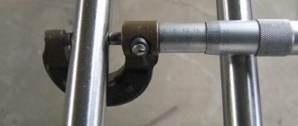
To measure the outside diameter of an inch or metric thread, you can use a regular caliper or micrometer.
The main dimensions of inch UNC fasteners are given in the table of inch threads
| Standard size | Outer diameter, inches | Outer diameter, mm | Drilling diameter, mm | Threads per inch | Pitch, mm |
| N 1 – 64 UNC | 0,073 | 1,854 | 1,50 | 64 | 0,397 |
| N 2 – 56 UNC | 0,086 | 2,184 | 1,80 | 56 | 0,453 |
| N 3 – 48 UNC | 0,099 | 2,515 | 2,10 | 48 | 0,529 |
| N 4 – 40 UNC | 0,112 | 2,845 | 2,35 | 40 | 0,635 |
| N 5 – 40 UNC | 0,125 | 3,175 | 2,65 | 40 | 0,635 |
| N 6 – 32 UNC | 0,138 | 3,505 | 2,85 | 32 | 0,794 |
| N 8 – 32 UNC | 0,164 | 4,166 | 3,50 | 32 | 0,794 |
| N 10 – 24 UNC | 0,190 | 4,826 | 4,00 | 24 | 1,058 |
| N 12 – 24 UNC | 0,216 | 5,486 | 4,65 | 24 | 1,058 |
| 1/4″ – 20 UNC | 0,250 | 6,350 | 5,35 | 20 | 1,270 |
| 5/16″ – 18 UNC | 0,313 | 7,938 | 6,80 | 18 | 1,411 |
| 3/8″ – 16 UNC | 0,375 | 9,525 | 8,25 | 16 | 1,587 |
| 7/16″ – 14 UNC | 0,438 | 11,112 | 9,65 | 14 | 1,814 |
| 1/2″ – 13 UNC | 0,500 | 12,700 | 11,15 | 13 | 1,954 |
| 9/16″ – 12 UNC | 0,563 | 14,288 | 12,60 | 12 | 2,117 |
| 5/8″ – 11 UNC | 0,625 | 15,875 | 14,05 | 11 | 2,309 |
| 3/4″ – 10 UNC | 0,750 | 19,050 | 17,00 | 10 | 2,540 |
| 7/8″ – 9 UNC | 0,875 | 22,225 | 20,00 | 9 | 2,822 |
| 1″ – 8 UNC | 1,000 | 25,400 | 22,25 | 8 | 3,175 |
| 1 1/8″ – 7 UNC | 1,125 | 28,575 | 25,65 | 7 | 3,628 |
| 1 1/4″ – 7 UNC | 1,250 | 31,750 | 28,85 | 7 | 3,628 |
| 1 3/8″ – 6 UNC | 1,375 | 34,925 | 31,55 | 6 | 4,233 |
| 1 1/2″ – 6 UNC | 1,500 | 38,100 | 34,70 | 6 | 4,233 |
| 1 3/4″ – 5 UNC | 1,750 | 44,450 | 40,40 | 5 | 5,080 |
| 2″ – 4 1/2 UNC | 2,000 | 50,800 | 46,30 | 4,5 | 5,644 |
| 2 1/4″ – 4 1/2 UNC | 2,250 | 57,150 | 52,65 | 4,5 | 5,644 |
| 2 1/2″ – 4 UNC | 2,500 | 63,500 | 58,50 | 4 | 6,350 |
| 2 3/4″ – 4 UNC | 2,750 | 69,850 | 64,75 | 4 | 6,350 |
| 3″ – 4 UNC | 3,000 | 76,200 | 71,10 | 4 | 6,350 |
| 3 1/4″ – 4 UNC | 3,250 | 82,550 | 77,45 | 4 | 6,350 |
| 3 1/2″ – 4 UNC | 3,500 | 88,900 | 83,80 | 4 | 6,350 |
| 3 3/4″ – 4 UNC | 3,750 | 95,250 | 90,15 | 4 | 6,350 |
| 4″ – 4 UNC | 4,000 | 101,600 | 96,50 | 4 | 6,350 |
Slicing technologies
Cylindrical pipe threads, which are of the inch type (both internal and external), can be cut manually or mechanically.
Manual thread cutting
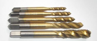
Cutting a thread using a hand tool, which uses a tap (for internal) or a die (for external), is performed in several steps.
- The pipe being processed is clamped in a vice, and the tool used is fixed in a driver (tap) or in a die holder (die).
- The die is put on the end of the pipe, and the tap is inserted into the inside of the latter.
- The tool used is screwed into the pipe or screwed onto its end by rotating a driver or die holder.
- To make the result cleaner and more precise, you can repeat the cutting procedure several times.
Cutting threads on a lathe
Mechanically, pipe threads are cut according to the following algorithm:
- The pipe being processed is clamped in the machine chuck, on the support of which a thread-cutting tool is fixed.
- At the end of the pipe, using a cutter, a chamfer is removed, after which the speed of movement of the caliper is adjusted.
- After bringing the cutter to the surface of the pipe, the machine turns on the threaded feed.
It should be borne in mind that inch threads are cut mechanically using a lathe only on tubular products whose thickness and rigidity allow this to be done. Making pipe inch threads mechanically allows you to obtain a high-quality result, but the use of such technology requires the turner to have the appropriate qualifications and certain skills.
Tightening torques
Tightening torques for UNC inch fasteners for SAE grade 5 and higher bolts and nuts are shown in the following table.
| Thread size, inches | Tightening torque for standard bolts and nuts | N*m*lbf-ft** |
| 1/4 | 12± 3 | 9±2 |
| 5/16 | 25 ± 6 | 18± 4,5 |
| 3/8 | 47± 9 | 35 ± 7 |
| 7/16 | 70± 15 | 50± 11 |
| 1/2 | 105± 20 | 75±15 |
| 9/16 | 160 ± 30 | 120± 20 |
| 5/8 | 215± 40 | 160 ± 30 |
| 3/4 | 370 ± 50 | 275 ± 37 |
| 7/8 | 620± 80 | 460 ± 60 |
| 1 | 900 ± 100 | 660 ± 75 |
| 11/8 | 1300 ± 150 | 950 ± 100 |
| 1 1/4 | 1800 ±200 | 1325 ±150 |
| 1 3/8 | 2400 ± 300 | 1800 ± 225 |
| 1 1/2 | 3100 ± 350 | 2300 ± 250 |
*1 Newton meter (N*m) is equal to approximately 0.1 kgm. ** Pound-force-foot is the British and American equivalent of N*m.
Marking of inch fasteners
Inch fasteners have a more complex marking system that does not allow visually, without the use of special tables, to determine the mechanical properties of the fastener. The most common markings on the heads of inch bolts and their correspondence to strength classes are shown in the table below.
| Marks on the head | Strength class according to SAE | Strength class of the replacement bolt, not lower |
| 1 or 2 | 6.8 | |
| 5 | 8.8 | |
| 6 | 10.9 |
How to determine the weight of a pipe
There are several ways to find out the mass of a pipe.
The easiest and fastest method is to use a directory or get information on a thematic website. The profile tables indicate the calculated weight of 1 linear meter. for various sizes. There are sites on the Internet where you can calculate the weight of a pipe using an online calculator. To do this, you need to know the wall thickness, internal or external diameter. Another option is to calculate the weight using the formula. This formula is prescribed in document GOST No. 8732. It is suitable for calculating the mass of pipes of any type. Therefore, the data obtained from such calculations will only be approximate. But in most cases there is no need to obtain the most accurate mass. In addition, the indicators obtained as a result of calculations using the formula are within the permissible error. Therefore, you can operate with such values.
Sources
- https://Avto-bolt.ru/dyuymovaya-rezba/
- https://traiv-komplekt.ru/articles/dyuymovaya-rezba-tablitsy-razmery-kharakteristiki/
- https://ooo-asteko.ru/sootvetstvie-rezby-v-dyuymah-i-millimetrah/
- https://domxoloda.ru/table-sizes/
- https://gidro.tech-group.pro/tablicy_perevoda_dyuymovyh_razmerov
- https://met-all.org/metalloprokat/metizy/dyujmovaya-rezba-razmery-tablitsa-gost.html
- https://www.rinscom.com/articles/dyuymovaya-rezba-osnovnye-otlichiya-ot-metricheskoy-parametry-i-markirovka/
- https://KanalizaciyaLite.ru/tr/diametr-trub-32-mm-skolko-eto-v-dyujmax