In the material:
- Features of choosing a drill for a tap
- Pre-hole diameter for metric taps
- How to choose a drill for a chipless tap
- Drill diameters for pipe (inch) taps
- How to choose drills for UNC/UNF taps
- Drill diameters for trapezoidal threads
- Where to buy drills for cutting rough threads for a tap?
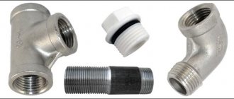
The tap is used for cutting internal threads and is a screw with cutting edges. However, before you tap the internal threads, you need to prepare a rough hole. For this, drills are used, which gives rise to a new problem, the essence of which is to select the correct drill diameter. The fact is that a hole with a larger diameter will lead to beveled threads, and a smaller one will ruin the tap. The thread pitch of taps can be different, and each pitch corresponds to a suitable drill diameter.
In this article we provide tables with drill diameters for popular threads for metric, trapezoidal, pipe and chipless taps. Information is presented for major and minor step. In addition, we will touch on the main problems that may be associated with the selection of tools for drilling rough holes.
Features of choosing a drill for a tap
When choosing a drill for a tap, consider the following recommendations.
- Make sure that the drill fits the material being processed. For most threading operations, a tool made of high-speed steel containing cobalt is sufficient. However, if the material is harder, use a carbide drill bit.
- The rough hole needs to be countersinked and chamfered. This will allow for better centering of the tap and will also provide better entry into the threads of bolts, studs, etc.
- Take into account the properties of the material. For brittle, hard and soft, tough metals, the hole diameter will be different. Thus, the diameter of a drill for an M8 thread in a soft material will be 6.8 mm, and in a hard material - 6.7 mm.
In this article you will find links to GOST standards that indicate which drill to choose for the existing tap. The documents specify hole sizes of varying precision and maximum diameter deviations. The diameters of holes for cutting threads in soft and viscous materials are also given here.
Types of instruments
The appropriate tool is selected depending on the characteristics of the material being processed, the required productivity and other parameters. Using different types of taps, you can cut metric or inch internal threads with a cylindrical or conical profile.
According to the method of conducting the process, models are distinguished:
- Pass-through (universal) . Their working part consists of three zones. The first performs rough cutting, the second – intermediate, and the third – finishing.
- Complete . To perform a full range of work, several tools are used - for roughing, intermediate and finishing cutting. The sets consist of three taps, less often of two (for roughing and finishing). For processing particularly strong metals, kits with 5 tools are used.
The tool is made of two types: for processing holes manually or using metal-cutting equipment.
- Machine-manual . Has a square shank. Works complete with a holder with two handles - a knob.
- Machine . Installed in the chuck of metalworking machines of various types.
Taps of different designs are used for cutting threads in blind and through holes:
- For non-passable holes, use a complete tool without a conical tip. The work is usually done with a crank.
- In through holes, threads are made using taps with a conical tip. Most often these are varieties of universal type tools.
The channels for removing chips have different shapes: straight, screw, shortened.
Chip channels of any shape are suitable for processing materials of low hardness. To tap threads in high-hardness materials, such as stainless and heat-resistant steels, use only a tool in which the cutting segments are staggered.
Pre-hole diameter for metric taps
We suggest that you familiarize yourself with GOST standards for metric threads, which are cut with standard taps of the most popular sizes M3, M4, M5, M6, M8, M10 and M12 with a basic pitch.
Brief table for the most common coarse pitch metric thread sizes:
| Tap (thread/main pitch) | Hole diameter (⌀ drill), mm |
| M3x0.5 | 2,5 |
| M4x0.7 | 3,3 |
| M5x0.8 | 4,2 |
| M6x1.0 | 5,0 |
| M8x1.25 | 6,8 |
| M10x1.5 | 8,5 |
| M12x1.75 | 10,2 |
| M14x2.0 | 12,0 |
| M16x2.0 | 14,0 |
| M18x2.5 | 15,4-15,6 |
| M20x2.5 | 17,4-17,6 |
Detailed table of drill sizes for metric threads, main pitch (DIN 13/GOST 24705):
| M | Pitch, mm | Internal diameter of nut thread, mm (additional according to ISO2 – 6H) | Drill diameter, mm (according to DIN336) |
| 1 | 0,25 | *0,774 | 0,75 |
| 1,1 | 0,25 | *0,874 | 0,85 |
| 1,2 | 0,25 | *0,974 | 0,95 |
| 1,4 | 0,3 | *1,128 | 1,1 |
| 1,6 | 0,35 | 1,321 | 1,25 |
| 1,8 | 0,35 | 1,521 | 1,45 |
| 2 | 0,4 | 1,679 | 1,6 |
| 2,2 | 0,45 | 1,838 | 1,75 |
| 2,5 | 0,45 | 2,138 | 2,05 |
| 3 | 0,5 | 2,599 | 2,5 |
| 3,5 | 0,6 | 3,010 | 2,9 |
| 4 | 0,7 | 3,422 | 3,3 |
| 4,5 | 0,75 | 3,878 | 3,7 |
| 5 | 0,8 | 4,334 | 4,2 |
| 6 | 1 | 5,153 | 5,0 |
| 7 | 1 | 6,153 | 6,0 |
| 8 | 1,25 | 6,912 | 6,8 |
| 9 | 1,25 | 7,912 | 7,8 |
| 10 | 1,5 | 8,676 | 8,5 |
| 11 | 1,5 | 9,676 | 9,5 |
| 12 | 1,75 | 10,441 | 10,2 |
| 14 | 2 | 12,210 | 12,0 |
| 16 | 2 | 14,210 | 14,0 |
| 18 | 2,5 | 15,744 | 15,5 |
| 20 | 2,5 | 17,744 | 17,5 |
| 22 | 2,5 | 19,744 | 19,5 |
| 24 | 3 | 21,252 | 21,0 |
| 27 | 3 | 24,252 | 24,0 |
| 30 | 3,5 | 26,771 | 26,5 |
| 33 | 3,5 | 29,771 | 29,5 |
| 36 | 4 | 32,270 | 32,0 |
| 39 | 4 | 35,270 | 35,0 |
| 42 | 4,5 | 37,799 | 37,5 |
| 45 | 4,5 | 40,799 | 40,5 |
| 48 | 5 | 43,297 | 43,0 |
| 52 | 5 | 47,297 | 47,0 |
| 56 | 5,5 | 50,796 | 50,5 |
| 60 | 5,5 | 54,796 | 54,5 |
| 64 | 6 | 58,305 | 58,0 |
| 68 | 6 | 62,305 | 62,0 |
*Tolerance range according to ISO1 – 4H.
Detailed table of drill sizes for fine pitch metric threads (DIN 13/GOST 24705):
| MxStep | Internal diameter of nut thread, mm (additional according to ISO2 - 6H) | Drill diameter, mm >(according to DIN336) | MxStep | Internal diameter of nut thread, mm (additional according to ISO2 - 6H) | Drill diameter, mm >(according to DIN336) | |
| 2×0,25 | *1,774 | 1,75 | 24×1 | 23,153 | 23 | |
| 2,2×0,25 | *1,974 | 1,95 | 24×1,5 | 22,676 | 22,5 | |
| 2,3×0,25 | 2,071 | 2,05 | 24×2 | 22,210 | 22 | |
| 2,5×0,35 | *2,184 | 2,15 | 25×1 | 24,153 | 24 | |
| 2,6×0,35 | 2,252 | 2,2 | 25×1,5 | 23,676 | 23,5 | |
| 3×0,35 | *2,684 | 2,65 | 26×1,5 | 24,676 | 24,5 | |
| 3,5×0,35 | *3,184 | 3,15 | 27×1,5 | 25,676 | 25,5 | |
| 4×0,35 | *3,684 | 3,65 | 27×2 | 25,210 | 25,0 | |
| 4×0,5 | 3,599 | 3,5 | 28×1,5 | 26,676 | 26,5 | |
| 5×0,5 | 4,599 | 4,5 | 28×2 | 26,210 | 26,0 | |
| 6×0,5 | 5,599 | 5,5 | 30×1 | 29,153 | 29,0 | |
| 6×0,75 | 5,378 | 5,2 | 30×1,5 | 28,676 | 28,5 | |
| 7×0,75 | 6,378 | 6,2 | 30×2 | 28,210 | 28,0 | |
| 8×0,5 | 7,599 | 7,5 | 32×1,5 | 30,676 | 30,5 | |
| 8×0,75 | 7,378 | 7,2 | 33×1,5 | 31,676 | 31,5 | |
| 8×1 | 7,153 | 7,0 | 33×2 | 31,210 | 31,0 | |
| 9×0,75 | 8,378 | 8,2 | 34×1,5 | 32,676 | 32,5 | |
| 9×1 | 8,153 | 8,0 | 35×1,5 | 33,676 | 33,5 | |
| 10×0,5 | 9,599 | 9,5 | 36×1,5 | 34,676 | 34,5 | |
| 10×0,75 | 9,378 | 9,2 | 36×2 | 34,210 | 34,0 | |
| 10×1 | 9,153 | 9,0 | 36×3 | 33,252 | 33,0 | |
| 10×1,25 | 8,912 | 8,8 | 38×1,5 | 36,676 | 36,5 | |
| 11×1 | 10,153 | 10,0 | 39×1,5 | 37,676 | 37,5 | |
| 12×0,75 | 11,378 | 11,2 | 39×2 | 37,210 | 37,0 | |
| 12×1 | 11,153 | 11,0 | 39×3 | 36,252 | 36,0 | |
| 12×1,25 | 10,912 | 10,8 | 40×1,5 | 38,676 | 38,5 | |
| 12×1,5 | 10,676 | 10,5 | 40×2 | 38,210 | 38,0 | |
| 13×1 | 12,153 | 12,0 | 40×3 | 37,252 | 37,0 | |
| 14×1 | 13,153 | 13,0 | 42×1,5 | 40,676 | 40,5 | |
| 14×1,25 | 12,912 | 12,8 | 42×2 | 40,210 | 40,0 | |
| 14×1,5 | 12,676 | 12,5 | 42×3 | 39,252 | 39,0 | |
| 15×1 | 14,153 | 14,0 | 45×1,5 | 43,676 | 43,5 | |
| 15×1,5 | 13,676 | 13,5 | 45×2 | 43,210 | 43,0 | |
| 16×1 | 15,153 | 15,0 | 45×3 | 42,252 | 42,0 | |
| 16×1,5 | 14,676 | 14,5 | 48×1,5 | 46,676 | 46,5 | |
| 18×1 | 17,153 | 17,0 | 48×2 | 46,210 | 46,0 | |
| 18×1,5 | 16,676 | 16,5 | 48×3 | 45,252 | 45,0 | |
| 18×2 | 16,210 | 16,0 | 50×1,5 | 48,676 | 48,5 | |
| 20×1 | 19,153 | 19,0 | 50×2 | 48,210 | 48,0 | |
| 20×1,5 | 18,676 | 18,5 | 50×3 | 47,252 | 47,0 | |
| 20×2 | 18,210 | 18,0 | 52×1,5 | 50,676 | 50,5 | |
| 22×1 | 21,153 | 21,0 | 52×2 | 50,210 | 50,0 | |
| 22×1,5 | 20,676 | 20,5 | 52×3 | 49,252 | 49,0 | |
| 22×2 | 20,210 | 20,0 | 63×1,5 | 61,676 | 61,5 |
Important!
In order to understand without a table which drill for the tap is optimal, you need to subtract its pitch from the nominal thread diameter. Let's consider the method using an M10x1.5 thread as an example.
- The nominal thread diameter is 10 mm.
- Step - 1.5 mm.
- We subtract the pitch from the thread diameter: 10 – 1.5 = 8.5 mm.
- We get the drill diameter: 8.5 mm.
It is allowed to round the result up. For example, round 9.75 to 9.8 mm. However, this method allows you to find out only an approximate value and is more suitable for domestic needs. In production, specialists rely on the tables specified in GOSTs and take into account the tolerances and features of the material being processed.
Classification of leroks
Thread cutting tools are distinguished according to the following characteristics:
- According to the method of producing threads - machine or manual.
- According to the materials from which this equipment is made.
- According to the profile of the threaded part on the final product.
- According to the characteristics of the thread being cut: its diameter and pitch.
Tools for obtaining internal threads are often called taps, but this is incorrect - such equipment is called taps.
A thread cutting tool is always used in conjunction with a die holder - equipment where the thread-forming tool is secured. The appearance of such devices is determined by the design of the lectern. In particular, for manual thread cutting, die holders are equipped with a handle and three to four gougons that secure the blade, which are evenly distributed along the arc of the seating surface. When machine-forming threaded profiles, the die holders have the form of a flat prism.
To universalize the designs of die holders, tool companies that produce die holders make their outer surface the same for the adjacent group of threads (for example, M10 and M12). The taps, designed to produce threads with the same diameter but different thread pitches, are also unified in their seats.
The standard marking of the lerka includes in its designation a letter that determines the type of thread - inch (D) or metric (M). Rarely, lugs with left-handed threads are also used (for example, in the seats of devices for tying cargo cables and ropes, in heating radiators, etc.). Then the Latin letters LH are added to the designation of lerki.
For trenches that form threads on pipes, the letter G is added to the designation. Such trenches can have a conical profile of the thread-forming part, and are used to produce threaded parts on pipes, in particular, on bends, adapters, etc.
The parameters and characteristics of domestically produced lechers are regulated by the requirements of GOST 9740.
How to choose a drill for a chipless tap
Choosing a drill for a chipless tap, which is used to extrude threads, has its own difficulties associated with metal deformation. During processing, the metal is deformed both in the direction of the hole axis and in the opposite direction. For this reason, the rough hole for rolling is usually made of a larger diameter than for cutting with chips.
For example, to cut an M8 thread with a pitch of 1.25 mm, you need to take a tap with a diameter of 6.8 mm, and to obtain an M8x1.25 thread by rolling (extruding) you need to drill a rough hole with a diameter of 7.45 mm. First, let's look at the table values for metric chipless taps.
Table of hole sizes for rolling pins, metric thread, coarse pitch (DIN 13/GOST 24705):
| M | Thread pitch | Inner diameter of nut thread (add. ISO2 - 7H) | Min. mm | Max. mm | Rough hole diameter (calculated value), mm |
| 1 | 0,25 | *0,785 | 0,89 | 0,91 | 0,9 |
| 1,1 | 0,25 | *0,885 | 0,99 | 1,01 | 1,0 |
| 1,2 | 0,25 | *0,985 | 1,09 | 1,11 | 1,1 |
| 1,4 | 0,3 | *1,142 | 1,24 | 1,27 | 1,25 |
| 1,6 | 0,35 | *1,321 | 1,44 | 1,48 | 1,45 |
| 1,8 | 0,35 | *1,521 | 1,66 | 1,68 | 1,67 |
| 2,0 | 0,4 | *1,679 | 1,84 | 1,86 | 1,85 |
| 2,2 | 0,45 | **1,838 | 2,02 | 2,04 | 2,03 |
| 2,5 | 0,45 | *2,138 | 2,30 | 2,34 | 2,3 |
| 3 | 0,5 | 2,639 | 2,79 | 2,82 | 2,8 |
| 3,5 | 0,6 | 3,050 | 3,24 | 3,28 | 3,25 |
| 4 | 0,7 | 3,466 | 3,69 | 3,73 | 3,7 |
| 4,5 | 0,75 | 3,924 | 4,16 | 4,2 | 4,2 |
| 5 | 0,8 | 4,384 | 4,64 | 4,68 | 4,65 |
| 6 | 1 | 5,217 | 5,51 | 5,59 | 5,55 |
| 7 | 1 | 6,217 | 6,55 | 6,6 | 6,55 |
| 8 | 1,25 | 6,982 | 7,41 | 7,48 | 7,45 |
| 9 | 1,25 | 7,982 | 8,41 | 8,48 | |
| 10 | 1,5 | 8,751 | 9,28 | 9,37 | 9,35 |
| 11 | 1,5 | 9,751 | 10,28 | 10,37 | |
| 12 | 1,75 | 10,531 | 11,16 | 11,25 | 11,2 |
| 14 | 2 | 12,310 | 13,02 | 13,14 | 13,1 |
| 16 | 2 | 14,310 | 15,02 | 15,14 | 15,1 |
| 18 | 2,5 | 15,854 | 16,75 | 16,89 | 16,9 |
| 20 | 2,5 | 17,854 | 18,75 | 18,89 | 18,9 |
*Tolerance range according to ISO1 – 5H. **Tolerance range according to ISO2 – 6H.
Table of hole diameters for rolling taps, metric thread, fine pitch (DIN 13/GOST 24705):
| MxStep | Inner diameter of nut thread (add. ISO2 - 7H) | Min. mm | Max. mm | Rough hole diameter (calculated value), mm |
| 2×0,25 | *1,785 | 1,9 | 1,91 | |
| 2,2×0,25 | *1,985 | 2,1 | 2,11 | |
| 2,3×0,25 | *2,071 | 2,2 | 2,21 | |
| 2,5×0,35 | 2,201 | 2,36 | 2,38 | 2,37 |
| 2,6×0,35 | 2,252 | 2,46 | 2,48 | 2,47 |
| 3×0,35 | *2,701 | 2,87 | 2,89 | 2,88 |
| 3,5×0,35 | *3,201 | 3,37 | 3,39 | 3,38 |
| 4×0,35 | *3,701 | 3,87 | 3,89 | |
| 4×0,5 | 3,639 | 3,79 | 3,82 | 3,8 |
| 5×0,5 | 4,639 | 4,79 | 4,82 | 4,8 |
| 6×0,5 | **5,599 | 5,8 | 5,83 | 5,8 |
| 6×0,75 | 5,424 | 5,63 | 5,7 | 5,7 |
| 7×0,75 | 6,424 | 6,67 | 6,72 | 6,7 |
| 8×0,5 | **7,599 | 7,8 | 7,83 | |
| 8×0,75 | 7,424 | 7,67 | 7,72 | 7,7 |
| 8×1 | 7,217 | 7,51 | 7,6 | 7,55 |
| 9×0,75 | 8,424 | 8,67 | 8,72 | 8,7 |
| 9×1 | 8,217 | 8,55 | 8,6 | 8,6 |
| 10×0,5 | **9,599 | 9,8 | 9,83 | 9,8 |
| 10×0,75 | 9,424 | 9,67 | 9,72 | 9,7 |
| 10×1 | 9,217 | 9,51 | 9,6 | 9,55 |
| 10×1,25 | 8,982 | 9,41 | 9,48 | 9,45 |
| 11×1 | 10,217 | 10,55 | 10,6 | 10,6 |
| 12×1 | 11,217 | 11,52 | 11,61 | 11,55 |
| 12×1,25 | 10,982 | 11,43 | 11,5 | 11,45 |
| 12×1,5 | 10,751 | 11,29 | 11,38 | 11,35 |
| 14×1 | 13,217 | 13,55 | 13,61 | 13,6 |
| 14×1,25 | 12,982 | 13,43 | 13,5 | 13,45 |
| 14×1,5 | 12,751 | 13,29 | 13,38 | 13,35 |
| 15×1 | 14,217 | 14,55 | 14,61 | 14,6 |
| 15×1,5 | 13,751 | 14,26 | 14,36 | 14,35 |
| 16×1 | 15,217 | 15,55 | 15,61 | 15,6 |
| 16×1,5 | 14,751 | 15,29 | 15,38 | 15,35 |
| 18×1 | 17,217 | 17,55 | 17,61 | 17,6 |
| 18×1,5 | 16,751 | 17,29 | 17,38 | 17,35 |
| 18×2 | 16,310 | 17,02 | 17,14 | 17,1 |
| 20×1 | 19,217 | 19,55 | 19,61 | 19,6 |
| 20×1,5 | 18,751 | 19,29 | 19,38 | 19,35 |
| 20×2 | 18,310 | 19,02 | 19,14 | 19,1 |
| 22×1,5 | 20,751 | 21,26 | 21,36 | |
| 22×2 | 20,310 | 21 | 21,15 | |
| 24×1,5 | 22,751 | 23,26 | 23,38 | |
| 24×2 | 22,310 | 23,01 | 23,16 | 23,1 |
*Tolerance range according to ISO1 – 5H. **Tolerance range according to ISO2 – 6H.
Now let's see which drill to choose for a chipless tap for cutting inch pipe threads.
Diameter table for Whitworth pipe thread rolling taps (DIN ISO 228/1):
| G | Threads per inch | Outer thread diameter, mm | Nut thread internal diameter, max. mm | Min. mm | Max. mm | Rough hole diameter (calculated value), mm |
| G 1/16″ | 28 | 7,723 | 6,843 | 7,24 | 7,32 | |
| G 1/8″ | 28 | 9,728 | 8,848 | 9,24 | 9,32 | 9,25 |
| G 1/4″ | 19 | 13,157 | 11,890 | 12,48 | 12,56 | 12,55 |
| G 3/8″ | 19 | 16,662 | 15,395 | 15,99 | 16,06 | 16,06 |
| G 1/2″ | 14 | 20,955 | 19,172 | 20,02 | 20,12 | 20,05 |
| G 5/8″ | 14 | 22,911 | 21,128 | 21,97 | 22,07 | |
| G 3/4″ | 14 | 26,441 | 24,658 | 25,5 | 25,6 | |
| G 7/8″ | 14 | 30,201 | 28,418 | 29,26 | 29,36 | |
| G1″ | 11 | 33,249 | 30,931 | 32,05 | 32,18 | |
| G 1 1/8″ | 11 | 37,897 | 35,579 | 36,7 | 36,83 | |
| G 1 1/4″ | 11 | 41,910 | 39,592 | 40,72 | 40,84 | |
| G 1 3/8″ | 11 | 44,323 | 42,005 | 43,13 | 43,26 | |
| G 1 1/2″ | 11 | 47,803 | 45,485 | 46,61 | 46,74 | |
| G 1 3/4″ | 11 | 53,746 | 51,428 | 52,55 | 52,68 | |
| G 2″ | 11 | 59,614 | 57,296 | 58,42 | 58,55 |
How to cut external threads using a die
To cut external threads manually, a special tool is used - a die holder with dies of various diameters.
Die holder with dies for different diameters
In hard-to-reach places, for example near walls, a die holder with a ratchet is used.
Selection of dies
Nominal thread diameter is the diameter at the vertices of the thread triangles. The die cuts the metal, forming depressions and leaving the tops intact, thus both the rod and the die must be the same diameter. The diameter of the thread, for example, is M3 - this is “M” - metric thread, and the number is the nominal diameter of the thread in mm. Accordingly, to cut a thread on a 3 mm rod, we take an M3 die. Measurements of the rod are made with a caliper.
To make the die cut better into the rod, a chamfer is cut off from its end.
Principle of thread cutting with a die
To secure the workpiece you will need a vice. The workpiece is firmly fixed in a vice and lubricated with machine oil for easier movement of the die, reducing friction and tool wear.
When cutting threads with a die, you must avoid large accumulations of chips in the chip removal holes.
The die is installed on the end of the part perpendicularly. With slight pressure, they begin to rotate the die holder clockwise if the thread is right-handed, respectively, if it is left-handed, then counterclockwise.
Cut the thread as follows:
- First make 2-3 turns.
- Then half a turn back to remove chips.
- Lubricate after every 3-4 turns, using a syringe.
- Etc.
Ring gauge
Cutting a thread with a die with your own hands (video)
Drill diameters for pipe (inch) taps
Here is a table with the dimensions of rough holes for pipe threads.
| G | Thread pitch, mm | Number of threads per 1 inch | Diameter of drill bit for thread, mm | Threaded hole diameter, mm | ||
| Nominal | Limit deviations for accuracy classes | |||||
| A | B | |||||
| G1/8 | 0,907 | 28 | 8,7 | 8,62 | +0,1 | +0,2 |
| G1/4 | 1,337 | 19 | 11,5 | 11,5 | +0,12 | +0,25 |
| G3/8 | 1,337 | 19 | 15 | 15 | +0,12 | +0,25 |
| G1/2 | 1,814 | 14 | 18,75 | 18,68 | +0,14 | +0,28 |
| G5/8 | 1,814 | 14 | 20,75 | 20,64 | +0,14 | +0,28 |
| G3/4 | 1,814 | 14 | 24,25 | 24,17 | +0,14 | +0,28 |
| G7/8 | 1,814 | 14 | 28 | 27,93 | +0,14 | +0,28 |
| G1 | 2,309 | 11 | 30,5 | 30,34 | +0,18 | +0,36 |
| G1 1/8 | 2,309 | 11 | 35 | 35 | +0,18 | +0,36 |
| G1 1/4 | 2,309 | 11 | 39 | 39 | +0,18 | +0,36 |
| G1 3/8 | 2,309 | 11 | 41,5 | 41,41 | +0,18 | +0,36 |
| G1 1/2 | 2,309 | 11 | 45 | 44,9 | +0,18 | +0,36 |
| G1 3/4 | 2,309 | 11 | 51 | 50,84 | +0,18 | +0,36 |
| G2 | 2,309 | 11 | — | 56,7 | +0,18 | +0,36 |
| G2 1/4 | 2,309 | 11 | — | 62,8 | +0,22 | +0,43 |
| G2 1/2 | 2,309 | 11 | — | 72,27 | +0,22 | +0,43 |
| G2 3/4 | 2,309 | 11 | — | 78,62 | +0,22 | +0,43 |
| G3 | 2,309 | 11 | — | 84,97 | +0,22 | +0,43 |
| G3 1/4 | 0,907 | 11 | — | 91,07 | +0,22 | +0,43 |
| G3 1/2 | 1,337 | 11 | — | 97,42 | +0,22 | +0,43 |
| G3 3/4 | 1,337 | 11 | — | 103,77 | +0,22 | +0,43 |
| G4 | 1,814 | 11 | — | 110,12 | +0,22 | +0,43 |
| G4 1/2 | 1,814 | 11 | — | 122,82 | +0,22 | +0,43 |
| G5 | 1,814 | 11 | — | 135,52 | +0,22 | +0,43 |
| G5 1/2 | 1,814 | 11 | — | 148,22 | +0,22 | +0,43 |
| G6 | 2,309 | 11 | — | 160,92 | +0,22 | +0,43 |
Basic cutting methods
You can cut threads on pipes in one of two ways:
- automatic - on machines, power tools;
- manually - using hand tools.
For living conditions, of course, manual technology is more relevant. Cutting threads on water pipes or other pipes by hand is often done using a die.
Solid dies for pipe threads, made of strong alloy steel, are available with a body diameter of up to 65 mm. Dies with a body diameter of up to 120 mm are available for metric threads. On the body of metric products there is a symbol “M”
A die is a simple device for cutting threads on pipes at home. The same tool is successfully used on industrial machines.
The device looks like a disk with several axial holes drilled along its inner diameter. The edges of these holes form several incisors (usually 8-10). The material for the dies is alloy steel or other hard alloys.
There are several types of such devices:
- solid;
- spring-loaded (split);
- clamp (sliding).
According to the design, the die is produced in the form of a circle, square, hexagon, or prism. The most common are disc (round) instruments. They are used for threading water pipes up to a diameter of 36 mm.
For ease of working with dies, use:
- simple knobs with locking screws - hand tools;
- threading chucks on lathes.
Cutting threads (metric, conical) of the best quality on pipes manually or on machines is provided by solid dies.
However, this type of tool, due to the rigidity of its own design, has its negative sides. The cutters wear out quickly.
A spring-loaded thread cutting tool is distinguished by the presence of a cut in the area of one of the axial holes. The presence of a cut reduces the load on the cutters, but at the same time the degree of rigidity required to achieve high cutting quality is reduced.
Spring-loaded (split) dies have a less rigid design, which makes it possible to cut threads on pipes and at the same time change the thread diameter in the range of 0.1-0.3 mm.
Such devices are characterized by increased wear resistance of the cutters, but do not provide high accuracy and cleanliness of thread cutting.
Sliding dies consist of two working parts. They are designed for installation in a fastening module - a clamp.
Fastening in the clamp is carried out by a mechanism consisting of a cracker and an adjusting screw. The screw adjusts the diameter size for thread cutting. Usually the die is equipped with a set of dies for several different diameters.
Method #1 - making pipe threads with dies
The process of creating a thread on a pipe with a die or die requires the mechanic to perform some preliminary actions:
- The surface of the pipe in the cutting area must be thoroughly cleaned.
- The end part of the pipe should be processed with a file (make an entrance chamfer).
- Apply lubricant to the surface to be treated to reduce resistance.
If possible, it is advisable to secure the pipe vertically, for example, in a bench vice, leaving free access to the upper part - the cutting area. The fastening force must be correctly calculated so as not to deform the pipe body.
Then take a pre-prepared driver with a roughing die (No. 1) of the required diameter and suitable thread characteristics.
An example of cutting a thread on a water pipe using a hand wrench. A die is inserted into the working cylinder of the driver and secured with two (four) bolts located opposite each other
The tool is held horizontally - perpendicular to the end area of the pipe. Place the roughing die onto the chamfer of the edge using the internal hole. Light pressure and successive short turns of 25-30° make the initial cut.
This work should be done carefully, slowly, constantly monitoring the right angle between the horizon of the ram and the vertical of the pipe.
Using this technique, the first two or three threads are carefully cut. Usually, after cutting the first two or three threads, the tool is firmly in its working position. Further, the right angle can no longer be controlled.
But the technology of cutting with short (without particularly strong traction) circular movements should be maintained until the end of the cut. It is recommended to periodically add lubricant at the cutting point.
After the first pass, twist the device and then repeat one or two more times with a finishing die (No. 2).
Method #2 - clump cutting technique
The die is a variation of the same die for cutting threads, including on pipes. A distinctive feature of the die is the ability to adjust the cutters.
A set of clamps for different sizes of pipe threads. Each of these devices is equipped with screws for fastening blocks with cutters. These screws can additionally change the thread diameter within small limits
There are clamps for manual use, as well as similar devices with an electric drive.
Option #1 - cutting with a hand clamp . Manual cutting of pipes is usually done with a clamp, which is installed in a ratchet holder. This holder makes the work of cutting pipe threads convenient and less complicated.
Of course, depending on the conditions of plumbing work, you can use other types of hand holders. For example, a standard locking knob with two handles.
The principle of creating a thread with a die is almost the same as the method of working with traditional dies:
- Clean the working surface of the pipe and make sure there are no defects.
- Sand the cut area until it has a distinct metallic sheen.
- Process the outer working part of the end edge at an angle of 45-60º (chamfer).
- Lubricate the prepared surface with technical petroleum jelly.
- Secure the pipe in a mechanical vice or hold it with a gas wrench.
After these procedures, the cutting tool (blank) is placed with the internal hole on the pipe chamfer and, with moderate, uniform pressure, they begin to rotate it with short reciprocating movements.
A convenient tool for working with a clamp is the so-called “ratchet” - a lever with idle reverse. Using such a hand tool, it is easy to cut threads on a pipe under different installation or repair conditions.
If a ratchet clamp is used as a holder, only forward cutting is carried out. It should be noted that the ratchet clamp is convenient to use when working in cramped conditions.
For example, when it is necessary to process a pipe laid in close proximity to a wall.
Option #2 - cutting with an electric clamp . Along with hand tools, electrically driven devices are widely used. The obvious advantage for the mechanic is a significant reduction in labor intensity.
But on the other hand, not all electric machines are capable of performing work in cramped conditions. In addition, when working with hand tools, it is possible to obtain a better result.
To obtain a similar result from electrical sockets, extensive experience with this tool is required.
Equipment for the clamp, supplemented with an electric drive. A modern, effective tool that significantly reduces the physical load of a mechanic. True, electric sockets are more often used in the professional sphere than in everyday life
Working with an electric clamp:
- Preparation of the pipe surface in the cutting area - cleaning, chamfering, lubrication.
- Fastening the pipe with devices capable of providing rigid fixation.
- Fixation at the starting point of the die holder with the clamp included in the kit.
- Checking the stroke and direction of rotation of the die.
- Cutting the first two or three turns in the jog mode.
Next, pipe threads are cut automatically. The cutting length is considered optimal when the upper edge of the die cutting heads reaches the leading edge of the pipe.
At this point, the operation of the device is stopped, the reverse rotation function is turned on, and the bug is twisted from the pipe with a push feed. Be sure to periodically moisten the cut area with oil throughout the process.
Method #3 - using lathes
Large-scale construction and repair work, as a rule, excludes the use of hand tools. Here, lathes are usually used to process the pipes accordingly.
Threading functions are supported by many universal lathes.
Lathes are used to produce threaded parts on pipes of different diameters. You can make threads of any configuration on a lathe
Using the machines, both internal and external pipe threads are made efficiently and easily. The pneumatic (or mechanical) fastening module of the lathe ensures high-quality reliable fastening of the pipe and precise supply of the workpiece to the cutter.
To perform thread-cutting functions, different types of cutters are used:
- rod,
- lamellar,
- intercalary
Work on lathes is carried out by specialists trained in this field and having the appropriate qualifications. Without experience and professional skills, trying to cut threads with your own hands on a machine is not recommended.
For home craftsmen who decide to take up plumbing and carve metal workpieces, the following tips will help them in their work:
How to choose drills for UNC/UNF taps
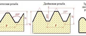
Inch cylindrical threads with coarse (UNC) and fine (UNF) are used less frequently in Russia than metric ones. Their profile is slightly different (55 degrees for the imperial versus 60 degrees for the metric), and their pitch is also measured in inches.
Here is a table of drill diameters for taps with American UNC/UNF threads.
| Inch UNC thread | |||
| Thread x Threads per inch | Drill diameter, mm | Thread x Threads per inch | Drill diameter, mm |
| 1/4x20 | 5,1 | 7/8x9 | 19,5 |
| 5/16x18 | 6,5 | 1x8 | 22,25 |
| 3/8x16 | 8 | 1 1/8x7 | 25 |
| 7/16x14 | 9,4 | 1 1/4x7 | 28,25 |
| 1/2x13 | 10,8 | 1 3/8x6 | 30,75 |
| 9/16x12 | 12,2 | 1 1/2x6 | 34 |
| 5/8x11 | 13,6 | 1 3/4x5 | 39,5 |
| 3/4x10 | 16,5 | 2x4 | 45 |
| Inch fine thread UNF | |||
| Thread x threads per inch | Drill diameter, mm | Thread x threads per inch | Drill diameter, mm |
| 1/4x28 | 5,5 | 3/4x16 | 17,5 |
| 5/16x24 | 6,9 | 7/8x14 | 20,5 |
| 3/8x24 | 8,5 | 1x12 | 23,25 |
| 7/16x20 | 9,9 | 1 1/8x12 | 26,5 |
| 1/2x20 | 11,5 | 1 1/4x12 | 29,75 |
| 9/16x18 | 12,9 | 1 3/8x12 | 33 |
| 5/8x18 | 14,5 | 1 1/2x12 | 36 |
Drill diameters for trapezoidal threads
| Trapezoidal thread Tr | |||
| Tap | Drill diameter, mm | Tap | Drill diameter, mm |
| Tr 8x1.5 | 6,6 | Tr 14x3 | 11,25 |
| Tr 10x1.5 | 8,6 | Tr 14x4 | 10,25 |
| Tr 10x2 | 8,2 | Tr 16x4 | 12,25 |
| Tr 10x3 | 7,5 | Tr 18x4 | 14,25 |
| Tr 12x2 | 10,2 | Tr 20x4 | 16,25 |
| Tr 12x3 | 9,25 | Tr 22x3 | 19,25 |
| Tr 14x2 | 12,2 | Tr 22x5 | 17,25 |
We have provided basic tables that will help you quickly select the right drill for the tap. You will find even more information, including tolerances based on the materials being processed, in the relevant standards:
- GOST 19257-73 “Holes for cutting metric threads”;
- GOST 21348-75 “Holes for cutting cylindrical pipe threads”;
- GOST 18844-73 “Chip-free taps”.
Stages of thread cutting with a machine-hand tap
Work order:
- The first step is marking in accordance with the drawings.
- According to the marks, punching is carried out with a sharply sharpened core.
- Drill with medium pressure at low speeds. The drill should be at right angles to the surface. Before starting work, the drill is lubricated. If the hole depth is large, then lubrication is carried out not only before starting, but also during operation. The depth of the blind hole should be slightly greater than the length being cut. If there is no reserve, the thread may be incomplete.
- The quality of the result can be improved by countersink processing, which reduces the taper and ensures parallelism of the side surfaces.
- The tap is secured in the driver, its tip is lubricated and inserted into the hole strictly at right angles to the surface. Make the first turn, lightly pressing the knob from above. After the first turn forward, make a half turn back to remove chips. Particular care is taken when using a multi-tool - it is fragile and easy to damage. It's easier to work with complete models.