Holes
GOST provides holes for threads with coarse pitch <1 =
1.0 - 2.2 mm.
26. Dimensions and maximum deviations of the diameters of holes in threads with fine pitch.
Dimensions, mm
| Nominal thread diameter d | Thread pitch P | Threaded hole diameter with tolerance range | ||||
| 4Н5Н; 5H; 5Н6Н; 6H; 7N | 6G; 7G | 4Н5Н; 5H | 5Н6Н; 6H; 6G | 7H; 7G | ||
| Denomination | Deviations | |||||
| 2,5 3 3,5 | 0,35 | 2,15 2,65 3,15 | 2,17 2,67 3,17 | +0,05 | +0,07 | — |
| 4 4,5 5 5,5 | 0,5 | 3,50 4,00 4,50 5,00 | 3,52 4,02 4,52 5,02 | +0,08 | +0,10 | +0,14 |
| 6 | 0,5 0,75 | 5,50 5,20 | 5,52 5,23 | +0,08 +0,11 | +0,10 +0,17 | +0,14 +0,22 |
| 8 | 0,5 0,75 1 | 7,50 7,20 6,95 | 7,52 7,23 7,00 | +0,08 +0,11 +0,17 | +0,10 +0,17 +0,20 | +0,14 +0,22 +0,26 |
| 10 | 0,5 0,75 1 1,25 | 9,50 9,20 8,95 8,70 | 9,53 9,23 9,00 8,75 | +0,08 +0,11 +0,17 +0,17 | +0,10 +0,17 +0,20 +0,20 | +0,14 +0,22 +0,26 +0,26 |
| 12 | 0,5 0,75 1 1,25 1,5 | 11,50 11,20 10,99 10,70 10,43 | 11,52 11,23 11,00 10,75 10,50 | +0,08 +0,11 +0,17 +0,17 +0,19 | +0,10 +0,17 +0,17 +0,20 +0,22 | +0,14 +0,22 +0,26 +0,26 +0,30 |
| 14 | 0,5 0,75 1 1,25 1,5 | 13,50 13,20 12,95 12,70 12,43 | 13,52 13,23 13,00 12,75 12,50 | +0,08 +0,11 +0,17 +0,17 +0,19 | +0,10 +0,17 +0,20 +0,20 +0,22 | +0,14 +0,22 +0,26 +0,26 +0,30 |
| 16 | 0,5 0,75 1 1,5 | 15,50 15,20 14,95 14,43 | 15,52 15,23 15,00 14,50 | +0,08 +0,11 +0,17 +0,19 | +0,10 +0,17 +0,20 +0,22 | +0,14 +0,22 +0,26 +0,30 |
| 18 | 0,5 0,75 1 1,5 2 | 17,50 17,20 16,95 16,43 15,90 | 17,52 17,23 17,00 16,50 15,95 | +0,08 +0,11 +0,17 +0,19 +0,24 | +0,10 +0,17 +0,20 +0,22 +0,30 | +0,14 +0,22 +0,26 +0,30 +0,40 |
| 20 | 0,5 0,75 1 1,5 2 | 19,50 19,20 18,95 18,43 17,90 | 19,52 19,23 19,00 18,50 17,95 | +0,08 +0,11 +0,17 +0,19 +0,24 | +0,10 +0,17 +0,20 +0,22 +0,30 | +0,14 +0,22 +0,26 +0,30 +0,40 |
| 22 | 0,5 0,75 1 1,5 2 | 21,50 21,20 20,95 20,43 19,90 | 21,52 21,23 21,00 20,50 19,95 | +0,08 +0,11 +0,17 +0,19 +0,24 | +0,10 +0,17 +0,20 +0,22 +0,30 | +0,14 +0,22 +0,26 +0,30 +0,40 |
| 24 | 0,75 1 1,5 2 | 23,20 22,95 22,43 21,90 | 23,23 23,00 22,50 21,95 | +0,11 +0,17 +0,19 +0,24 | +0,17 +0,20 +0,22 +0,30 | +0,22 +0,26 +0,30 +0,40 |
| 27 | 0,75 1 1,5 2 | 26,20 25,95 25.43 24,90 | 26,23 26,00 25,50 24,95 | +0,11 +0,17 +0,19 +0,24 | +0,17 +0,20 +0,22 +0,30 | +0,22 +0,22 +0,30 +0,40 |
| 30 | 0,75 1 1,5 2 3 | 29,20 28,95 28,43 27,90 26,85 | 29,23 29,00 28,50 27,95 26,90 | +0,11 +0,17 +0,19 +0,24 +0,30 | +0,17 +0,20 +0,22 +0,30 +0,40 | +0,22 +0,26 +0,30 +0,40 +0,53 |
| 33 | 0,75 1 1,5 2 3 | 32,20 31,95 31,43 30,90 29,85 | 32,23 32,00 31,50 30,95 29,90 | +0,11 +0,17 +0,19 +0,24 +0,30 | +0,17 +0,20 +0,22 +0,30 +0,40 | +0,22 +0,26 +0,30 +0,40 +0,53 |
| 36 | 1 1,5 2 3 | 34,95 34,43 33,90 32,85 | 35,00 34,50 33,95 32,90 | +0,17 +0,19 +0,24 +0,30 | +0,20 +0,22 +0,30 +0,40 | +0,26 +0,30 +0,40 +0,53 |
| 39 | 1 1,5 2 3 | 37,95 37,43 36,90 35,85 | 38,00 37,50 36,95 35,90 | +0,17 +0,19 +0,24 +0,30 | +0,20 +0,22 +0,30 +0,40 | +0,26 +0,30 +0,40 +0,53 |
| 42 | 1 1,5 2 3 4 | 40,95 40,43 39,90 38,85 37,80 | 41,00 40,50 39,95 38,90 37,85 | +0,17 +0,19 +0,24 +0,30 +0,36 | +0,20 +0,22 +0,30 +0,40 +0,48 | +0,26 +0,30 +0,40 +0,53 +0,62 |
| 45 | 1 1,5 2 3 4 | 43,95 43,43 42,90 41,85 40,80 | 44,00 43,50 42,95 41,90 40,85 | +0,17 +0,19 +0,24 +0,30 +0,36 | +0,20 +0,22 +0,30 +0,40 +0,48 | +0,26 +0,30 +0,40 +0,53 +0,62 |
GOST provides holes for threads with D = 1.0 - 200 mm and for c1
3rd row. GOST provides a method for determining the diameters of holes for cutting metric threads for materials of high viscosity.
27. Diameters of holes for cutting inch conical threads with a profile angle of 60° according to GOST 6111-52
The dimensions of the holes for threading apply to metals and alloys that do not have high viscosity.
Dimensions, mm
| With cone deployment | Without cone deployment |
| Thread size, inches | Number of steps per 1″ | Thread pitch P | Internal thread diameter d1 | Diameter of hole with reaming to cone | Drilling depth L | Hole diameter without taper | ||||
| dc | do | |||||||||
| Denomination | Deviations | Denomination | Deviations | Denomination | Deviations | |||||
| 1/16 1/8 | 27 | 0,941 | 6,389 8,766 | 6,00 8,30 | +0,16 +0,20 | 6,39 8,76 | +0,09 | 13 14 | 6,3 8,7 | +0,14 |
| 1/4 3/8 | 18 | 1,411 | 11,314 14,797 | 10,70 14,25 | +0,24 | 11,31 14,80 | +0,13 | 20 21 | 11,2 14,7 | +0,24 |
| 1/2 3/4 | 14 | 1,814 | 18,321 23,666 | 17,50 22,90 | +0,28 | 18,32 23,66 | +0,17 | 26,5 | 18,25 23,50 | +0,24 +0,28 |
| 1 11/4 | 111/2 | 2,209 | 29,694 38,451 | 28,75 37,43 | +0,28 +0,34 | 29,69 38,45 | 33,5 34,5 | 29,6 38,5 | +0,28 +0,34 | |
| 11/8 | 44,520 | 43,50 | +0,34 | 44,52 | 34,5 | 44,5 | +0,34 | |||
28. Diameters of holes for cutting cylindrical pipe threads (according to GOST 21348-75)
Diameters of holes for cutting cylindrical pipe threads in accordance with GOST 6357-81 in products made of steel in accordance with GOST 380-94, GOST 4543-71, GOST 1050-88 and GOST 5632-72 (except for nickel-based alloys) and copper in accordance with GOST 859-78 .
| Nominal thread size, inches | Number of steps per 1″ | Step | Threaded hole diameter | Nominal thread size, inches | Number of steps per 1″ | Step | Diameter of threaded hole | ||||
| Denomination | Deviations for accuracy classes | Denomination | Deviations for accuracy classes | ||||||||
| A | IN | ||||||||||
A
B 1/8 28 0.907 8.62 +0.10 +0.20 4/21 21/223/43 31/431/233/44 41/25 51/26 11 2.309 62.80 72.27 78.62 84 .97 91.07 97.42 103.77 110.12 122.82 135.52 148.22 160.92 +0.22 +0.43 1/4 3/8 19 1.337 11.50 15.00 +0 .12 +0.25 1/2 5/8 3/4 7/8 14 1.814 18.68 20.64 24.17 27.93 +0.14+0.28 1 11/8 11/413/811/ 213/4 2 11 2.309 30.34 35.00 39.00 41.41 44.90 50.84 56.70 +0.18+0.36I. DIMENSIONS
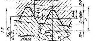
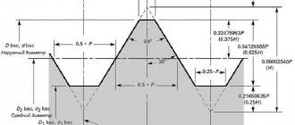
1. The profile and dimensions of a conical inch thread with a profile angle of 60° must correspond to the drawings. 1 and table. 1.
Table 1
| Designation, thread size | Number of threads per 1¢¢ | Size in mm | |||||||
| Thread pitch | Thread length | thread diameter in the main plane | Internal diameter of thread at the end of the pipe | Working coil height | |||||
| from the end of the pipe to the main plane | |||||||||
| outer | interior | ||||||||
| d 2 = | d = | d 1 = | |||||||
Notes:
1. When screwing together without tension a pipe and a coupling with nominal thread sizes, the main plane of the pipe thread coincides with the end of the coupling.
2. Size d T
reference.
3. Instead of a 1/16 ¢¢ thread, it is allowed to use an M6´1 conical thread in accordance with GOST 19853.
4. The number of turns with a full profile in a threaded connection should not be less than two.
5. It is allowed to reduce the size l
2 (distance from the main plane to the end of the pipe), in this case the requirement of clause 4 of this standard regarding the difference in dimensions
l
1
-l
2 must be met.
The thread pitch is measured parallel to the thread axis.
The bisector of the profile angle is perpendicular to the thread axis.
Symbol for tapered thread 3 /
4 ¢¢
:
II. TOLERANCES
2. The pipe thread (external) is checked according to the average diameter with a thread ring gauge in accordance with GOST 6485. The axial displacement of the main plane of the pipe (Fig. 2) relative to the nominal location should not exceed (thread pitch).
Figure 2 - Pipe thread (external)
3. The coupling thread (internal) is checked according to the average diameter with a thread plug gauge in accordance with GOST 6485. The axial displacement of the main plane of the coupling (Fig. 3) relative to the nominal location should not exceed (thread pitch).
Fig.3 - Coupling thread (internal)
(Changed edition, Amendment No. 1, 2).
4. The difference in sizes must be no less than the difference between the nominal sizes and indicated in Table 1.
5. The deviation of the distances between the tops and bottoms of the threads of the tube and coupling from the line of the average diameter of the thread (and according to Figure 4) should not exceed those given in Table 2.
table 2
| Thread size designation | |
Figure 4 - Deviation of the distances between the tops and bottoms of the tube and coupling threads from the line of the average diameter of the thread
Damn.4
(Changed edition, Amendment No. 2).
6. Deviations of half the profile angle, slope angle () and deviation in thread pitch (deviations of the distances between any turns) should not exceed those given in Table 3.
Table 3
| Thread size designation | Prev. off | ||||
| half profile angle | slope angle | by thread pitch | |||
| for external thread | for internal thread | at a length of up to 10 mm | at the length of St. 10 mm | ||
CONICAL INCH THREAD WITH PROFILE ANGLE 60°
GOST 6111-52
USSR STATE COMMITTEE ON STANDARDS
STATE STANDARD OF THE USSR UNION
Approved by the Office for Standardization under the Council of Ministers of the USSR on January 10, 1952. The introduction date is set
from 01.10.52
Tested in 1984
Failure to comply with the standard is punishable by law
This standard applies to threaded connections of fuel, oil, water and air pipelines of machines and machine tools. Note. 1. In pipelines made of steel water and gas pipes in accordance with GOST 3262-75, connections with conical threads must be made in accordance with GOST 6211-81. 2. (Deleted, Amendment No. 2).
1. The profile and dimensions of a conical inch thread with a profile angle of 60° must correspond to the drawings. 1 and table. 1.
Table 1
| Designation, thread size | Number of threads per 1¢¢ | Size in mm | Thread pitch | Thread length | thread diameter in the main plane | Internal diameter of thread at the end of the pipe | Working coil height | from the end of the pipe to the main plane | outer | interior | d 2 = | d = | d 1 = | |||||||||||
Notes: 1. When screwing together without interference a pipe and a coupling with nominal thread sizes, the main plane of the pipe thread coincides with the end of the coupling. 2. Size d T
is for reference.
3. Instead of a 1/16 ¢ ¢ thread, it is allowed to use an M6 ´ 1 conical thread in accordance with GOST 19853-74. 4. The number of turns with a full profile in a threaded connection should not be less than two. 5. It is allowed to reduce the size l
2 (the distance from the main plane to the end of the pipe), while the requirement of clause 4 of this standard regarding the difference in sizes
l
1
- l
2 must be met.
The thread pitch is measured parallel to the thread axis.
The bisector of the profile angle is perpendicular to the thread axis.
Symbol for tapered thread 3/
4 ¢ ¢
:
TO
3
/
4 ¢ ¢
GOST 6111-52 (Changed edition, Amendment No. 2).
2. The pipe thread (external thread) is checked by the average diameter with a thread ring gauge in accordance with GOST 6485-69.
The axial displacement of the main plane of the pipe D l
2 (Fig. 2) relative to the nominal location should not exceed
±P
(thread pitch).
Crap.
2 (Changed edition, Amendment No. 1, 2).
3. The coupling thread (internal thread) is checked according to the average diameter using a thread plug gauge in accordance with GOST 6485-69.
The axial displacement of the main plane of the coupling D l
2 (Fig. 3) relative to the nominal location should not exceed
±P
(thread pitch).
(Changed edition, Amendment No. 1, 2).
4. The difference in sizes
l
1 -
l
2 must be no less than the difference indicated in the table.
1 nominal sizes l
1 and
l
2 .5.
The deviation of the distances between the tops and bottoms of the tube and coupling threads from the line of the average thread diameter (d h
1 and d
h
2 according to Fig. 4) should not exceed:
table 2
| Thread size designation | h 1 = | d h 1 = d |
| 1/16 and 1/8¢¢ | ||
| 1/4 and 3/8¢¢ | ||
| 1/2 and ¾ ¢ ¢ | ||
INTERSTATE STANDARD
Date of introduction 01.10.52
This standard applies to threaded connections of fuel, oil, water and air pipelines of machines and machine tools.
Notes.
1. In pipelines made of steel water and gas pipes in accordance with GOST 3262, connections with conical threads must be made in accordance with GOST 6211-81.
2. (Deleted, Amendment No. 2).
II. TOLERANCES
2. The pipe thread (external thread) is checked by the average diameter with a thread ring gauge in accordance with GOST 6485. Axial displacement of the main plane of the pipe D l
2 (Fig. 2) relative to the nominal location should not exceed
±P
(thread pitch).
3. The coupling thread (internal thread) is checked according to the average diameter using a thread plug gauge in accordance with GOST 6485-69. Axial displacement of the main plane of the coupling D l
2 (Fig. 3) relative to the nominal location should not exceed
±P
(thread pitch).
(Changed edition, Amendment No. 1, 2).
4. Size difference l
1 -
l
2 should be no less than the difference indicated in the table.
1 nominal sizes l
1 and
l
2.
5. Deviation of the distances between the tops and bottoms of the tube and coupling threads from the line of the average thread diameter (d h
1 and d
h
2 according to devil. 4) must not exceed:
table 2
(Changed edition, Amendment No. 2).
6. Deviations of half the profile angle, slope angle (j/2) and deviation in thread pitch (deviations in the distances between any turns) should not exceed:
Table 3
(Changed edition, Amendment No. 1, 2).
INFORMATION DATA
1. DEVELOPED AND INTRODUCED by the Ministry of Machine Tool Industry
Huge spaceships are flying towards the earth. Vivid evidence of visiting extraterrestrial guests
2022-02-05 14:54:27
Why does hot water freeze faster than cold water?
2022-02-05 14:54:27
Which water freezes faster - hot or cold?
2022-02-05 14:54:27
GOST 6111-52
STATE STANDARD OF THE USSR UNION
CONICAL INCH THREAD WITH PROFILE ANGLE 60°
GOST 6111-52
USSR STATE COMMITTEE ON STANDARDS
Moscow
STATE STANDARD OF THE USSR UNION
| CONICAL INCH THREAD WITH PROFILE ANGLE 60° | GOST 6111-52* Instead of OST 20010-38 |
Approved by the Office for Standardization under the Council of Ministers of the USSR on January 10, 1952. The introduction date is set
from 01.10.52
Tested in 1984
Failure to comply with the standard is punishable by law
This standard applies to threaded connections of fuel, oil, water and air pipelines of machines and machine tools.
Note.
1. In pipelines made of steel water and gas pipes in accordance with GOST 3262-75, connections with conical threads must be made in accordance with GOST 6211-81.
2. (Deleted, Amendment No. 2).
I. DIMENSIONS
1. The profile and dimensions of a conical inch thread with a profile angle of 60° must correspond to the drawings. 1 and table. 1.
Table 1
| Designation, thread size | Number of threads per 1¢¢ | Size in mm | |||||||
| Thread pitch | Thread length | thread diameter in the main plane | Internal diameter of thread at the end of the pipe | Working coil height | |||||
| working | from the end of the pipe to the main plane | ||||||||
| average | outer | interior | |||||||
| inches | n | R | l 1 | l 2 | d 2= | d = | d 1= | d T | H |
| 1/16 | 27 | 0,941 | 6,5 | 4,064 | 7,142 | 7,895 | 6,389 | 6,135 | 0,753 |
| 1/8 | 27 | 0,941 | 7,0 | 4,572 | 9,519 | 10,272 | 8,766 | 8,480 | 0,753 |
| ¼ | 18 | 1,411 | 9,5 | 5,080 | 12,443 | 13,572 | 11,314 | 10,997 | 1,129 |
| 3/8 | 18 | 1,411 | 10,5 | 6,096 | 15,926 | 17,055 | 14,797 | 14,416 | 1,129 |
| ½ | 14 | 1,814 | 13,5 | 8,128 | 19,772 | 21,223 | 18,321 | 17,813 | 1,451 |
| ¾ | 14 | 1,814 | 14,0 | 8,611 | 25,117 | 26,568 | 23,666 | 23,128 | 1,451 |
| 1 | 11½ | 2,209 | 17,5 | 10,160 | 31,461 | 33,228 | 29,694 | 29,059 | 1,767 |
| 1¼ | 11½ | 2,209 | 18,0 | 10,668 | 40,218 | 41,985 | 38,451 | 37,784 | 1,767 |
| 1½ | 11½ | 2,209 | 18,5 | 10,668 | 46,287 | 48,054 | 44,520 | 43,853 | 1,767 |
| 2 | 11½ | 2,209 | 19,0 | 11,074 | 58,325 | 60,092 | 56,558 | 55,866 | 1,767 |
Notes:
1. When screwing together without tension a pipe and a coupling with nominal thread sizes, the main plane of the pipe thread coincides with the end of the coupling.
2. Size d T
reference.
3. Instead of a 1/16¢¢ thread, it is allowed to use an M6´1 conical thread in accordance with GOST 19853-74.
4. The number of turns with a full profile in a threaded connection should not be less than two.
5. It is allowed to reduce the size l
l
1
- l
must be met .
Crap. 1
The thread pitch is measured parallel to the thread axis.
The bisector of the profile angle is perpendicular to the thread axis.
Symbol for tapered thread 3/
4¢¢
:
TO
3
/
4¢¢
GOST 6111-52
(Changed edition, Amendment No. 2).
II. TOLERANCES
2. The pipe thread (external thread) is checked by the average diameter with a thread ring gauge in accordance with GOST 6485-69. Axial displacement of the main plane of the pipe D l
2 (Fig. 2) relative to the nominal location should not exceed
±P
(thread pitch).
Crap. 2
(Changed edition, Amendment No. 1, 2).
3. The coupling thread (internal thread) is checked according to the average diameter using a thread plug gauge in accordance with GOST 6485-69. Axial displacement of the main plane of the coupling D l
2 (Fig. 3) relative to the nominal location should not exceed
±P
(thread pitch).
Crap. 3
(Changed edition, Amendment No. 1, 2).
4. Size difference l
1-
l
2 should be no less than the difference indicated in the table.
1 nominal sizes l
1 and
l
2.
5. Deviation of the distances between the tops and bottoms of the tube and coupling threads from the line of the average thread diameter (d h
1 and d
h
2 according to devil. 4) must not exceed:
table 2
| Thread size designation | h 1= | dh 1=d |
| mm | ||
| 1/16 and 1/8¢¢ | 0,3765 | -0,045 |
| 1/4 and 3/8¢¢ | 0,5645 | -0,065 |
| 1/2 and ¾¢¢ | 0,7255 | -0,085 |
| 1 — 2¢¢ | 0,8835 | -0,085 |
Crap. 4
(Changed edition, Amendment No. 2).
6. Deviations of half the profile angle, slope angle (j/2) and deviation in thread pitch (deviations in the distances between any turns) should not exceed:
Table 3
| Thread size designation inches | Maximum deviation | ||||
| half profile angle | slope angle | by thread pitch | |||
| for external thread | for internal thread | at a length of up to 10 mm | at the length of St. 10 mm | ||
| mm | |||||
| 1/16 and 1/8¢¢ | ±1° | +12¢ | -12¢ | ±0,02 | ±0,04 |
| -6¢ | +6¢ | ||||
| 1/4 — 2¢¢ | ±45¢ | +10¢ | -10¢ | ||
| -5¢ | +5¢ | ||||
(Changed edition, Amendment No. 1, 2).
I. DIMENSIONS
I. DIMENSIONS
1. The profile and dimensions of a conical inch thread with a profile angle of 60° must correspond to Figure 1 and Table 1.
Fig. 1 - Conical inch thread
; ; ; taper Fig.1
The thread pitch is measured parallel to the thread axis. The bisector of the profile angle is perpendicular to the thread axis.
Example of a symbol for a tapered thread:
K
GOST 6111-52
Table 1 Dimensions in millimeters
| Designation, thread size, inches | Number of threads per | Thread pitch | Thread length | Thread diameter in the main plane | Internal diameter of thread at the end of the pipe | Working coil height | |||
| from the end of the pipe to the main plane | outer | interior | |||||||
Notes:
1. When screwing together without tension a pipe and a coupling with nominal thread sizes, the main plane of the pipe thread coincides with the end of the coupling.
2. Size is for reference.
3. Instead of threads, it is allowed to use conical threads M6x1 in accordance with GOST 19853.
4. The number of turns with a full profile in a threaded connection should not be less than two.
5. It is allowed to reduce the size (distance from the main plane to the end of the pipe), while the requirement of paragraph 4 regarding dimensions must be met.
NPT/NPTF tapered thread: main characteristics and standards
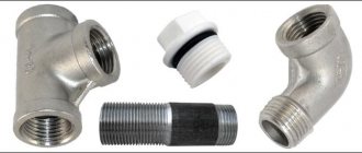
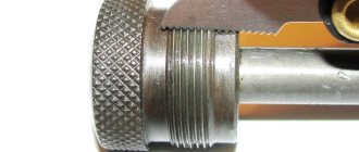
Appearance of a tapered NPT thread NPT/NPTF (national pipe taper/national pipe tapered fuel) thread is an American standard for tapered pipe threads. This standard applies to pipes and fittings that are manufactured in the USA.
NPT tapered pipe thread complies with GOST 6111-52 “Inch tapered thread with a profile angle of 60 degrees”, which is valid in most CIS countries.
The United States National Hydraulic Transmission Association advises against the use of NPT and NPTF standards in hydraulics. But despite this, the use of these standards is very widespread.
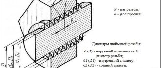
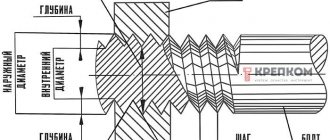
NPT thread diagram
Types of inch threads:
- NPT – thread with a taper of 1:16 and a profile angle of 60°. This thread complies with ANSI B1.21.1, FED-STD-H28/7 standards.
- NPS – cylindrical thread.
- NPTF - sealed inch thread with a profile angle of 60°, sealing occurs due to thread compression. This type of inch thread complies with SAE J476, ANSI B1.20.3, FED-STD-H28/8 standards.
Main parameters of the most common NPTF threaded connections:
| Nominal diameter, inch | Main diameter, mm | Threaded hole, mm | Threads per inch | Pitch, mm |
| NPTF 1/16″ | 7.870 | 6.00 | 27 | 0.940 |
| NPTF 1/8″ | 10.217 | 8.25 | 27 | 0.940 |
| NPTF 1/4″ | 13.577 | 10.70 | 18 | 1.411 |
| NPTF 3/8″ | 17.016 | 14.10 | 18 | 1.411 |
| NPTF 1/2″ | 21.211 | 17.40 | 14 | 1.814 |
| NPTF 3/4″ | 26.566 | 22.60 | 14 | 1.814 |
| NPTF 1″ | 33.195 | 28.50 | 11.5 | 2.209 |
| NPTF 1 1/4″ | 41.952 | 37.00 | 11.5 | 2.209 |
| NPTF 1 1/2″ | 48.021 | 43.50 | 11.5 | 2.209 |
| NPTF 2″ | 60.060 | 55.00 | 11.5 | 2.209 |
| NPTF 2 1/2″ | 72.642 | 65.50 | 8 | 3.175 |
| NPTF 4″ | 113.913 | 107.00 | 8 | 3.175 |
Main parameters of the most common NPT threaded connections:
| Nominal diameter, inch | Main diameter, mm | Threaded hole, mm | Threads per inch | Pitch, mm |
| NPT 1/16″ | 7.870 | 6.00 | 27 | 0.940 |
| NPT 1/8″ | 10.217 | 8.25 | 27 | 0.940 |
| NPT 1/4″ | 13.577 | 10.70 | 18 | 1.411 |
| NPT 3/8″ | 17.016 | 14.10 | 18 | 1.411 |
| NPT 1/2″ | 21.211 | 17.40 | 14 | 1.814 |
| NPT 3/4″ | 26.566 | 22.60 | 14 | 1.814 |
| NPT 1″ | 33.195 | 28.50 | 11.5 | 2.209 |
| NPT 1 1/4″ | 41.952 | 37.00 | 11.5 | 2.209 |
| NPT 1 1/2″ | 48.021 | 43.50 | 11.5 | 2.209 |
| NPT 2″ | 60.060 | 55.00 | 11.5 | 2.209 |
| NPT 2 1/2″ | 72.642 | 65.50 | 8 | 3.175 |
| NPT 4″ | 113.913 | 107.00 | 8 | 3.175 |
| NPT 5″ | 141,300 | 134,384 | 8 | 3.175 |
| NPT 6″ | 168,275 | 161,191 | 8 | 3.175 |
| NPT 8″ | 219,075 | 211,673 | 8 | 3.175 |
| NPT 10″ | 273,050 | 265,311 | 8 | 3.175 |
| NPT 12″ | 323,850 | 315,793 | 8 | 3.175 |
To create an NPT (NPTF) connection, special threading machines with a tap (die or threading head) are used.
BREXIT brings to your attention equipment with which you can cut NPT (NPTF) threads on pipes and workpieces with high quality:
- Die heads from 1/2 to 2 inches. Designed for high-quality, high-performance thread cutting. Safe and quick replacement.
- Manual threading dies from 1/2 to 1.1/4 inches. Designed for cutting conical pipe threads on water, electrical or gas pipes. It has high performance and is easy to transport.
- Manual threading dies from 1/2 to 2 inches. Can be widely used in equipment installation and construction industry, ideal for increasing labor productivity, reducing construction time, ensuring its quality, and reducing labor intensity.
- Electric threading machines from 1/2 to 2 inches. High-performance threading machine for mobile and stationary use. Suitable for long-term, intensive use in the workshop and on the construction site, used in the installation of heating and water supply systems and in mass production. The machine cuts precise threads of very high quality.
- Electric threading machines from 1/2 to 3 inches. The machine is designed for cutting screw and cylindrical threads on pipes. Used to produce precise, reliable threaded connections on pipes and bolts in accordance with codes. It is designed for long-term industrial use.
- Electric threading machines from 1/2 to 4 inches. The machine is designed for cutting pipe and metric threads. Used for the manufacture of precise, reliable threaded connections on pipes and studs in accordance with standards.
NPT threads are used in connections with increased tightness requirements. Connections with such threads are able to withstand strong pressure of the circulating medium through the pipeline.
To buy equipment for cutting NPT (NPTF) tapered threads on pipes, contact BREXIT managers by contact numbers: +375 (17) 256-22-55, +375 (29) 602-00-80, +375 (29) 766 -07-00, we will tell you in detail about the operating features, design and specifics of this type of equipment.
Not Found
INTERSTATE STANDARD
| CONICAL INCH THREAD WITH PROFILE ANGLE 60° | GOST 6111-52* |
Date of introduction 01.10.52
This standard applies to threaded connections of fuel, oil, water and air pipelines of machines and machine tools.
Note.
1. In pipelines made of steel water and gas pipes in accordance with GOST 3262-75, connections with conical threads must be made in accordance with GOST 6211-81.
2. (Deleted, Amendment No. 2).
1. The profile and dimensions of a conical inch thread with a profile angle of 60° must correspond to the drawings. 1 and table. 1.
Crap. 1
The thread pitch is measured parallel to the thread axis.
The bisector of the profile angle is perpendicular to the thread axis.
Example of symbol for tapered thread 3/
4¢¢
:
K
3
/
4¢¢
GOST 6111-52
(Changed edition, Amendment No. 2).
Table 1
Dimensions in millimeters
| Designation, thread size, inches | Number of threads per 1¢¢ n | Thread pitch R | Thread length | Thread diameter in the main plane | Internal diameter of thread at the end of the pipe dT | Working coil height H | |||
| working l 1 | from the end of the pipe to the main plane l 2 | average d 2= | outer d = | interior d 1= | |||||
| 1/16 | 27 | 0,941 | 6,5 | 4,064 | 7,142 | 7,895 | 6,389 | 6,135 | 0,753 |
| 1/8 | 7,0 | 4,572 | 9,519 | 10,272 | 8,766 | 8,480 | |||
| ¼ | 18 | 1,411 | 9,5 | 5,080 | 12,443 | 13,572 | 11,314 | 10,997 | 1,129 |
| 3/8 | 10,5 | 6,096 | 15,926 | 17,055 | 14,797 | 14,416 | |||
| ½ | 14 | 1,814 | 13,5 | 8,128 | 19,772 | 21,223 | 18,321 | 17,813 | 1,451 |
| ¾ | 14,0 | 8,611 | 25,117 | 26,568 | 23,666 | 23,128 | |||
| 1 | 11½ | 2,209 | 17,5 | 10,160 | 31,461 | 33,228 | 29,694 | 29,059 | 1,767 |
| 1¼ | 18,0 | 10,668 | 40,218 | 41,985 | 38,451 | 37,784 | |||
| 1½ | 18,5 | 46,287 | 48,054 | 44,520 | 43,853 | ||||
| 2 | 19,0 | 11,074 | 58,325 | 60,092 | 56,558 | 55,866 | |||
Notes:
1. When screwing together without tension a pipe and a coupling with nominal thread sizes, the main plane of the pipe thread coincides with the end of the coupling.
2. dT
reference.
3. Instead of a 1/16¢¢ thread, it is allowed to use an M6´1 conical thread in accordance with GOST 19853-74.
4. The number of turns with a full profile in a threaded connection should not be less than two.
5. It is allowed to reduce the size l
l
1
- l
must be met .
2. The pipe thread (external thread) is checked by the average diameter with a thread ring gauge in accordance with GOST 6485-69. Axial displacement of the main plane of the pipe D l
2 (Fig. 2) relative to the nominal location should not exceed
±P
(thread pitch).
Crap. 2
(Changed edition, Amendment No. 1, 2).
3. The coupling thread (internal thread) is checked according to the average diameter using a thread plug gauge in accordance with GOST 6485-69. Axial displacement of the main plane of the coupling D l
2 (Fig. 3) relative to the nominal location should not exceed
±P
(thread pitch).
Crap. 3
(Changed edition, Amendment No. 1, 2).
4. Size difference l
1-
l
2 should be no less than the difference indicated in the table.
1 nominal sizes l
1 and
l
2.
5. Deviation of the distances between the tops and bottoms of the tube and coupling threads from the line of the average thread diameter (d h
1 and d
h
2 according to devil. 4) must not exceed:
table 2
| Thread size designation | h 1= | dh 1=d |
| mm | ||
| 1/16 and 1/8¢¢ | 0,3765 | -0,045 |
| 1/4 and 3/8¢¢ | 0,5645 | -0,065 |
| 1/2 and ¾¢¢ | 0,7255 | -0,085 |
| 1 — 2¢¢ | 0,8835 | |
Crap. 4
(Changed edition, Amendment No. 2).
6. Deviations of half the profile angle, slope angle (j/2) and deviation in thread pitch (deviations in the distances between any turns) should not exceed those given in table. 3.
Table 3
| Thread size designation inches | Maximum deviation | ||||
| half profile angle | slope angle | by thread pitch | |||
| for external thread | for internal thread | at a length of up to 10 mm | at the length of St. 10 mm | ||
| mm | |||||
| 1/16¢¢ and 1/8¢¢ | ±1° | +12¢ | -12¢ | ±0,02 | ±0,04 |
| -6¢ | +6¢ | ||||
| ¼¢¢ – 2¢¢ | ±45¢ | +10¢ | -10¢ | ||
| -5¢ | +5¢ | ||||
(Changed edition, Amendment No. 1, 2).
INFORMATION DATA
1. DEVELOPED AND INTRODUCED by the Ministry of Machine Tool Industry
2. APPROVED AND ENTERED INTO EFFECT by the Office for Standardization under the Council of Ministers of the USSR on January 10, 1952.
3. INSTEAD OST 20010-38
4. REFERENCE REGULATIVE AND TECHNICAL DOCUMENTS
| Designation of the referenced technical document | Item number |
| GOST 3262-75 | Introductory part |
| GOST 6211-81 | » |
| GOST 6485-69 | 2, 3 |
| GOST 19853-74 | 1 |
5. The validity period was lifted according to Gosstandart Decree dated December 18, 1984 No. 4538 (IUS 3-85)
6. EDITION with Amendments No. 1, 2, approved in December 1969, December 1984 (IUS 1-70, 3-85)
Diameter of hole for GOST thread (Table)
The reference tables contain the dimensions of the diameters of holes for threading according to GOST 9150-59, GOST 6357-52, GOST 6111-52 and GOST 6211-52
1. The tables are for reference, issued on the basis of the plant’s guidelines 01.2РМ31-65 and normals МН5384-5389-64 and are intended for foremen, technologists and workers of main and auxiliary production.
2. The sizes of holes for threads with large pitches are highlighted in bold text.
3. The diameter of holes indicated without tolerances is carried out according to class 4 accuracy.
Diameters of holes for threading according to GOST 9150-59
| Nominal thread diameter | Diameters of holes for threading according to GOST 9150-59 | |||||||||||||
| Thread pitches S | ||||||||||||||
| 0,2 | 0,25 | 0,3 | 0,35 | 0,4 | 0,45 | 0,5 | 0,6 | 0,7 | 0,75 | 0,8 | 1 | 1,25 | 1,5 | |
| 1 | 0,8 | 0,75 | ||||||||||||
| 1,4 | 1,1 | |||||||||||||
| 1,6 | 1,25 | |||||||||||||
| 2,0 | 1,75 | 1,6 | ||||||||||||
| 2,5 | 2,15 | 2,05 | ||||||||||||
| 3 | 2,65 | 2,5 | ||||||||||||
| 3,5 | 3,15 | 2,9 | ||||||||||||
| 4 | 3,5 | 3,3 | ||||||||||||
| 4,5 | 4 | 3,8 | ||||||||||||
| 5 | 4,5 | 4,2 | ||||||||||||
| 6 | 5,5 | 5,2 | 5 | |||||||||||
| 8 | 7,5 | 7,2 | 7 | 6,7 | ||||||||||
| 10 | 9,5 | 9,2 | 9 | 8,7 | 8,5 | |||||||||
| Nominal thread diameter | Diameter of holes for threading according to GOST 9150-59 | |||||||||
| Thread pitches S | ||||||||||
| 0,75 | 1 | 1,25 | 1,5 | 1,75 | 2 | 2,5 | 3 | 3,5 | 4 | |
| 12 | 11,2 | 11 | 10,7 | 10,5 | 10,2 | |||||
| 14 | 13,2 | 13 | 12,7 | 12,5 | 11.9A5 | |||||
| 16 | 15,25 | 15 | 14,5 | 14 | ||||||
| 18 | 17 | 16,5 | 16 | 15.35A5 | ||||||
| 20 | 18,95 | 18,45 | 18 | 17.35A5 | ||||||
| 22 | 20,95 | 20,45 | 20 | 19.35A5 | ||||||
| 24 | 22,45 | 21.85A5 | 20.85A5 | |||||||
| 27 | 25,45 | 25 | 23.85A5 | |||||||
| 30 | 28,45 | 28 | 26.85A5 | |||||||
| 33 | 29.85A5 | 29.35A5 | ||||||||
| 36 | 32.8A5 | 31.8A5 | ||||||||
| 39 | 34.8A5 | |||||||||
| Nominal thread diameter | Diameters of holes for threading according to GOST 9150-59 | |||||||||
| Thread pitches S | ||||||||||
| 1 | 1,5 | 2 | 3 | 4 | 4,5 | 5 | 5,5 | 6 | ||
| 42 | 40,95 | 40,45 | — | 38,9 | 37.8A5 | 37,ZA5 | — | — | — | |
| 45 | 43,95 | 43,45 | 42,95 | 41,9 | 40.8A5 | 40,ZA5 | — | — | — | |
| 48 | 46,95 | 46,45 | 45,95 | 44,9 | 43.8A5 | 42.8A5 | — | — | ||
| 52 | 50,43 | 45,95 | 48,9 | 47.8A5 | — | 46.8A5 | — | — | ||
| 56 | 54,43 | 53,9 | 52,9 | 51,9 | — | — | 50,ZA5 | — | ||
| 60 | 58,4 | 57,9 | 56,9 | 55,9 | — | — | 54,ZA5 | — | ||
| 64 | 62,4 | 61,9 | 60,9 | 59,9 | — | — | — | 57.8A5 | ||
| 68 | 66,4 | 65,9 | 64,9 | 63,9 | — | — | — | 61.8A5 | ||
| 72 | 70,4 | 69,9 | 68,9 | 67,9 | — | — | — | 65.8A5 | ‘ | |
| 76 | 74,4 | 73,9 | 72,9 | 71,9 | — | — | — | 69.8A5 | ||
| 80 | 78,4 | 77,9 | 76,9 | 75,9 | — | — | — | 73.8A5 | ||
| 85 | 83,4 | 82,9 | 81,9 | 80,9 | — | — | — | 78.8A5 | ||
| 90 | 88,4 | 87,9 | 86,9 | 85,9 | — | — | — | 83.75A5 | ||
| For metals of high viscosity / (aluminum-magnesium alloys) | ||||||||||||||
| Nominal thread diameter | Diameter for holes for threading according to GOST 9150-59 | |||||||||||||
| Thread pitches S | ||||||||||||||
| 0,25 | 0,3 | 0,35 | 0,4 | 0,45 | 0,5 | 0,6 | 0,7 | 0,8 | 1 | 1,25 | 1,5 | 1,75 | 2 | |
| 1 | 0,8 | |||||||||||||
| 1,4 | 1.15 | |||||||||||||
| 1,6 | 1,3 | |||||||||||||
| 2 | 1,65 | |||||||||||||
| 2,5 | 2,15 | |||||||||||||
| 3 | 2,6 | |||||||||||||
| 3,5 | 3 | |||||||||||||
| 4 | 3,35 | |||||||||||||
| 5 | 4,25 | |||||||||||||
| 6 | 5,1 | |||||||||||||
| 8 | 6,8 | |||||||||||||
| 10 | 8,6 | |||||||||||||
| 12 | 10,8 | 10,6 | ||||||||||||
| 14 | 12,6 | 12,1 | ||||||||||||
Diameters of holes for cutting cylindrical pipe threads according to GOST 6357-52
| Diameters of holes for cutting cylindrical pipe threads according to GOST 6357-52 | ||
| Thread designation, inches | drill diameter, mm | |
| thread accuracy class | ||
| 2 | 3 | |
| 1/8 | 8.65A4 | 8.7A5 |
| 1/4 | 11.5A4 | 11.5A5 |
| 3/8 | 15A4 | 15A5 |
| 1/2 | 18.7A, | 18.7A5 |
| 5/8 | 20,7+0,12 | 20.7A5 |
| 3/4 | 24,2+0,15 | 24.2A5 |
| 7/8 | 28+0,12 | 28A5 |
| 1 | 30,43+0,16 | 30,43+0,29 |
| 1·1/8 | 35A4 | 35A5 |
| 1·1/4 | 39A4 | 39A5 |
| 1·3/8 | — | 41.5A5 |
| 1·1/2 | — | 45A5 |
Diameters of holes for threading according to OST NKTP 1260
| Diameters of holes for cutting inch threads according to OST NKTP 1260 | |||
| Thread designation, inches | Drill diameter, mm | Thread designation, inches | Drill diameter, mm |
| 3/16 | 3,6 | 1 | 22 |
| 1/4 | 5 | 1·1/8 | 24,75 |
| 5/16 | 6,4 | 1·1/4 | 27,75 |
| 3/8 | 7,8 | 1·3/8 | 30,25 |
| 7/16 | 9,1 | 1·1/2 | 33,5 |
| 1/2 | 10,4 | 1·5/8 | 35,75 |
| 9/16 | 12 | 1·3/8 | 39 |
| 5/8 | 13,3 | 1·7/8 | 41,5 |
| 3/4 | 16,25 | 2 | 44,5 |
| 7/8 | 19,25 | ||
Hole diameter GOST 6111-52
| Diameter of holes for cutting inch conical threads with reaming to a cone, GOST 6111-52 | ||||
| Thread diameter | Number of threads per 1″ | dc | do | Drill depth. e mm |
| 1/8 | 27 | 8,ZA5 | 8.76A4 | 15 |
| 1/4 | 18 | 10.7A5 | 11.31A4 | 20 |
| 3/8 | 14.25A5 | 14.8A4 | 22 | |
| 1/2 | 14 | 17.5A5 | 18.32A4 | 28 |
| 3/4 | 22.9A5 | 23.66A4 | 28 | |
| 1 | 11·1/2 | 28.75A5 | 29.69A4 | 35 |
| 1·1/4 | 37.43A5 | 38.45A4 | 36 | |
| 1·1/2 | 43.5A5 | 44.52A4 | 36 | |
| 2 | 55.5A4 | 56.54A4 | 37 | |
Hole diameter GOST 6211-52
| Diameter of holes for cutting conical pipe threads with reaming to a cone, GOST 6211-52 | ||||
| Thread diameter | Number of threads per 1″ | dc | d° | I'll drill the depth. e mm |
| 1/8 | 28 | 8.1A5 | 8.57A4 | 15 |
| 1/4 | 19 | 10.8A5 | 11.45A4 | 20 |
| 3/8 | 14.25A5 | 14,95+0,1 | 24 | |
| 1/2 | 14 | 17.9A5 | 18,63+0,1 | 29 |
| 3/4 | 23.25A5 | 24,12+0,1 | 31 | |
| 1 | 11 | 29.25A5 | 30.30А3а | 37 |
| 1·1/4 | 37.75A5 | 38.95A3a | 40 | |
| 1·1/2 | 43.5A5 | 44.83A3a | 42 | |
| 2 | 55A5 | 56.54A3a | 44 | |
Source of information: PA “Mashzavod im. October Revolution" 1986.