Inch thread parameters
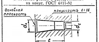
Requirements for standard parameters of cylindrical inch threads are specified in GOST 6111-52. Basic characteristics of threaded connections such as pitch and diameter are also indicated here.
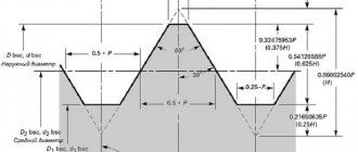
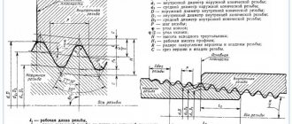
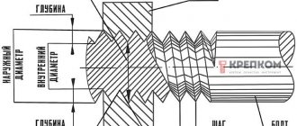
- The outer diameter is the distance between the top points of the threaded ridges on opposite sides of the pipe. To find it out, you can use a ruler or caliper.
- Internal diameter is the distance from one lowest point of the cavity between the threaded ridges to the other, located on the opposite side of the pipe.
Basic parameters of inch threads
Knowing the outer and inner diameters of an inch thread, you can calculate the height of its profile. To do this, it is enough to determine the difference between the diameters.
The pitch of an inch thread refers to the distance that separates two adjacent crests (or two adjacent valleys). The thread pitch usually does not exceed 3 mm, so high-precision rulers are used to measure it.
Measuring the pitch of an inch thread
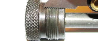
Checking the thread pitch
Compliance with the inch thread pitch according to the table is a necessary condition for the performance of the connection. Therefore, when slicing, it is recommended to check the compliance of this parameter. Thread pitch measurement is carried out using a gauge, thread gauge, mechanical gauge and other special tools.
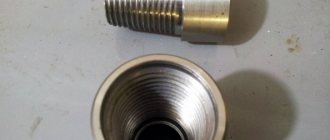
A simple method of checking using a template is also used, which uses a part with a counter thread that obviously complies with the standard. When checking external threads, for example on a pipe or bolt, a fitting or coupling with a standard internal thread is used as a template. The part being tested is screwed into a template. If it is completely screwed in and a tight connection is formed, then the thread pitch corresponds to the standard. If the part does not screw in or a loose connection is formed, it means that the thread is cut at the wrong pitch. Checking a product with an internal thread is performed using a similar method, but the template is a part with a standard external thread onto which the element being tested is screwed.
Another way to check the pitch, as well as other thread parameters, involves using a thread gauge. This is a plate that has serrations that exactly match a certain standard thread in size and other parameters. The thread gauge is applied to the cut thread being checked. At the same time, its jagged part must precisely coincide with its ridges and depressions, ensuring a tight fit.
Differences between inch and metric threads
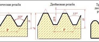
Metric and inch threads differ in the number of turns per thread pitch and different angles of inclination at the apex. For inch threads it is sharper and equals 55 degrees. The rest of the differences come from this.
- Due to the sharper angle of inclination, the profile of the threaded ridges changes. Inch joints have longer ridges but are less wide. The metric profile has more balanced ridges in shape (wider and not as long).
- Due to the difference in profiles, it is not possible to connect parts with metric and inch threads. The fasteners will be very fragile and leaky, which may lead to leakage of liquids during transportation.
Differences in the profile of imperial, metric and pipe threads
Where is which one used?
Metric threads are used all over the world in various fields of activity. They are used in the production of fasteners, household appliances, industrial equipment, automobiles, and plumbing products.
Interesting: What is surface hardening of steel
Inch threads are actively used in the USA, Canada, and some European countries. The only area of activity where they replace metric connections is plumbing.
Inch threaded connections have one important feature that metric threads do not have. When measuring tenths of a millimeter, various difficulties may arise and the accuracy of the measurement may decrease. The measurement process for inch connections uses ¼ inch increments. This improves the accuracy of measurements and simplifies designation.
Table of sizes of inch and metric threads
You can find out how the sizes of metric threads relate to the sizes of inch threads using the data in the table below.
Similar sizes of metric and various varieties of inch threads in the range of approximately Ø8-64 mm
Basic rules for slicing
- To correctly cut inch or metric threads, you must adhere to the following recommendations:
- Accurately select a drill of the required diameter. The hole diameters for UNF and UNC threads are shown in the tables above.
- Drill a hole strictly at right angles to the plane.
- Carry out cutting in a reciprocating motion. After two forward revolutions, make a backward revolution to remove chips.
- If there are two or three taps in the set, pass strictly by numbers - first with the first draft number, then with the second.
- It is advisable to use a lubricant to reduce friction.
Types of inch threads
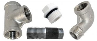
Inch threads can be cylindrical or conical. With a cylindrical connection, the dimensions of the outer and inner diameters are maintained along the entire length of the spare part. The threaded pitch has a fixed size, and the number of threads is related to the pitch. Spare parts with such a connection are more durable and reliable.
With a tapered connection, the thread has a variable diameter. The most widely used threads are those with a tapering diameter, in which the diameter at the base is larger than the diameter at the tail of the spare part. Parts with a tapered connection are often double marked, indicating not only the initial but also the final diameter. Inch tapered threads are stronger and wear out more slowly, but they are more difficult to apply, and errors in the procedure can seriously deteriorate the quality of the connection.
Kinds
Threaded connections differ not only in design features and shape, but also in other parameters - application surface, direction of threads.
On the application surface
The thread can be:
- Internal. It is created on the internal surfaces of cylindrical or conical parts (for various products, it plays the role of a covering one).
- Outdoor. It is applied to the outer surfaces of conical and cylindrical workpieces (for various parts, it is the covered surface).
Interesting: What is resistance welding and its types
Towards
Threaded connections are:
- Right-handed. Slice clockwise;
- Left-handed. Slice counterclockwise.
Inch thread cutting technology
Inch pipe thread cutting can be done manually or mechanically. Let's describe both options.
Method 1: Tapping by hand
Inch threads are cut manually using a tap (internal thread) or a die (external thread). Operations are carried out in the following sequence.
- The pipe is clamped in a vice, and the tool is fixed: if it is a tap, then in the driver, if it is a die, then in the die holder.
- The die is put on the end of the pipe, the tap is inserted into its lumen.
- The tool is screwed into the pipe or screwed onto its end by rotating a knob or die holder.
- If necessary, to achieve a more accurate result, the procedure for cutting inch threads is repeated several times.
Method 2: Cutting threads on a lathe
The mechanical method involves cutting inch threads on a lathe. During the work you need to adhere to this algorithm.
- The pipe is clamped in a machine chuck, on the support of which a thread-cutting tool is installed.
- The end of the pipe is chamfered with a cutter, after which the cutting speed is adjusted.
- After bringing the cutter to the surface of the pipe, the machine turns on the threaded feed.
It is possible to cut inch pipe threads on a lathe only if the products have a sufficient reserve of rigidity and strength. The mechanical method guarantees an accurate and high-quality result, but requires great skills from the master.
How to determine the pitch
More often, the inch thread pitch is determined using tables and specialized tools, but if there is no access to such equipment and tabular parameters, you can use other methods:
- Using a nut and bolt. You need to select a bolt for the nut that will screw in as freely as possible. Carry out calculations using a ruler and calipers.
- Using dye and paper. Cut a strip from a sheet of thick paper that, when folded, will fit inside the threaded connection without any problems. Apply dye to the internal threads. Place a strip of paper inside and press it against the applied dye with any thin object. There should be an imprint on the paper, by which you can determine the pitch between the turns.
Interesting: DIY cold forging of metal
Inch threaded connections are used in the assembly of pipelines for various purposes. They provide high strength to the entire structure and can withstand high pressure and water hammer. Recently, such compounds have begun to gain increasing popularity in the production of household appliances and electronics.
Accuracy classes and rules for marking inch threads
Inch threads according to GOST can correspond to one of the accuracy classes: 1, 2 or 3. The letter A (corresponds to external thread) or B (internal) occupies the adjacent place with the number indicating the accuracy class. Note that the 1st class of accuracy corresponds to the coarsest threads, and the 3rd class is the most precise, and the most stringent requirements are imposed on them.
To understand what parameters a specific threaded element corresponds to, you need to understand the symbols that are printed on it. The label contains the following information:
- nominal inch thread size;
- number of turns per inch of length;
- group;
- accuracy class.
The marking is applied to the part itself or packaging with parts and is an alphanumeric code of the following type: T1 T2 X Y1 Y2 - Z.
This code is deciphered as follows.
- T1 - the parameter indicates the category of the threaded spare part and can have several values: M (metric thread), MK (conical), Tr (trapezoidal single-start), S (thrust single-start), G (cylindrical pipe).
- T2 - indicates the outer diameter of the spare part; for inch threads it is indicated in inches.
- X is a separator symbol that does not carry any semantic load, but is required to be applied according to GOST.
- Y1 is the width of the thread pitch, which is indicated in millimeters even on inch threads. In rare cases, a parameter may be indicated in inches, but then two notches are placed next to the number, which indicate that we are looking at inches.
- Y2 is the direction of the threaded screw. There is a left-hand thread, the parameter is designated as LH. If it's on the right, they let him through.
- - also refers to delimiter characters that separate the main part of the code from the Z parameter.
- Z is a parameter that indicates the thread accuracy class. Can take the form of designations 4k, 6h, 6E, 8G, 8D, etc.
An example of a symbol for an inch thread
Interpretation of inch thread markings
Let us look at the designation of inch threads in the technical documentation using the example of marking G 2” LH-2-40.
- G - indicates that the pipe thread is cylindrical.
- The number 2 indicates the outer diameter size in inches.
- LH - these letters indicate that the thread is left-handed.
- Number 2 informs about the accuracy class.
- The number 40 indicates the screw length.
Tool design
The UNF/UNC tap is a screw with flutes and corresponding sharpening of the front, back and other corners. The main elements of the tool are the cutting (taking) and calibrating parts, grooves for removing chips. The cutting part is made of high-speed steel or hard alloy. A suitable shank is available for manual use or installation in a chuck.
The advantage of the tool is the simplicity and manufacturability of the design, as well as high cutting accuracy and the ability to work due to self-feeding. The difficulty is the need to apply large cutting forces and friction forces, and difficulties in removing chips.
Depending on the design, UNF/UNC taps are divided into:
- manual or metalworking;
- machine-manual;
- machine;
- nuts and others.
Thread according to OST-1260
| Nominal Thread Diameter (inches) | Dimensions in mm | |||||||
| Thread diameter | Gaps | Thread pitch | Number of threads per 1? | Profile height | ||||
| outer | average | interior | ||||||
| d | d0 | dav | d1 | With? | e? | S | P | t2 |
| 3/16 | 4,762 | 4,085 | 3,408 | 0,132 | 0,152 | 1,058 | 24 | 0,677 |
| 1/4 | 6,350 | 5,537 | 4,724 | 0,150 | 0,186 | 1,270 | 20 | 0,814 |
| 5/16 | 7,938 | 7,034 | 6,131 | 0,158 | 0,209 | 1,411 | 18 | 0,903 |
| 3/8 | 9,525 | 8,509 | 7,492 | 0,165 | 0,238 | 1,588 | 16 | 1,017 |
| (7/16) | 11,112 | 9,951 | 8,789 | 0,182 | 0,271 | 1,814 | 14 | 1,162 |
| 1/2 | 12,700 | 11,345 | 9,989 | 0,200 | 0,311 | 2,117 | 12 | 1,355 |
| (9/16) | 14,288 | 12,932 | 11,577 | 0,208 | 0,313 | 2,117 | 12 | 1,355 |
| 5/8 | 15,875 | 14,397 | 12,918 | 0,225 | 0,342 | 2,309 | 11 | 1,479 |
| 3/4 | 19,050 | 17,424 | 15,798 | 0,240 | 0,372 | 2,540 | 10 | 1,626 |
| 7/8 | 22,225 | 20,418 | 18,611 | 0,265 | 0,419 | 2,822 | 9 | 1,807 |
| 1 | 25,400 | 23,367 | 21,334 | 0,290 | 0,466 | 3,175 | 8 | 2,033 |
| 1 1/8 | 28,575 | 26,252 | 23,929 | 0,325 | 0,531 | 3,629 | 7 | 2,323 |
| 1 1/4 | 31,750 | 29,427 | 27,104 | 0,330 | 0,536 | 3,629 | 7 | 2,323 |
| (1 3/8) | 34,925 | 32,215 | 29,504 | 0,365 | 0,626 | 4,233 | 6 | 2,711 |
| 1 1/2 | 38,100 | 35,390 | 32,679 | 0,370 | 0,631 | 4,233 | 6 | 2,711 |
| (1 5/8) | 41,275 | 38,022 | 34,770 | 0,425 | 0,750 | 5,080 | 5 | 3,253 |
| 1 3/4 | 44,450 | 41,198 | 37,945 | 0,430 | 0,755 | 5,080 | 5 | 3,253 |
| (1 7/8) | 47,625 | 44,011 | 40,397 | 0,475 | 0,833 | 5,644 | 4 1/2 | 3,614 |
| 2 | 50,800 | 47,186 | 43,572 | 0,480 | 0,838 | 5,644 | 4 1/2 | 3,614 |
| 2 1/4 | 57,150 | 53,084 | 49,019 | 0,530 | 0,341 | 6,350 | 4 | 4,066 |
| 2 1/2 | 63,500 | 59,434 | 55,369 | 0,530 | 0,941 | 6,350 | 4 | 4,066 |
| 2 3/4 | 69,850 | 65,204 | 60,557 | 0,590 | 1,073 | 7,257 | 3 1/2 | 4,647 |
| 3 | 76,200 | 71,554 | 66,907 | 0,590 | 1,073 | 7,257 | 3 1/2 | 4,647 |
| 3 1/4 | 82,550 | 77,546 | 72,542 | 0,640 | 1,158 | 7,815 | 3 1/4 | 5,004 |
| 3 1/2 | 88,900 | 83,896 | 78,892 | 0,640 | 1,158 | 7,815 | 3 1/4 | 5,004 |
| 3 3/4 | 95,250 | 89,829 | 84,409 | 0,700 | 1,251 | 8,467 | 3 | 5,421 |
| 4 | 101,600 | 96,179 | 90,759 | 0,700 | 1,251 | 8,467 | 3 | 5,421 |
Why is this important to know?
Every car owner who repairs a car with his own hands has at least once encountered a situation where a nut of the same size does not fit onto a bolt of a suitable diameter. The reason lies in the fact that the thread applied to the “problem” part differs from the one cut on the product being screwed on.
This confirms that the carvings on them are different from each other. Therefore, for trouble-free tightening, you will need to select a screw or nut with the same thread.
Thread according to OST-266
- The main thread dimensions of GOST 6357-81 (BSP) are shown in the table below.
- Comment on the table below.
- d is the outer diameter of the external thread (pipe);
- D—outer diameter of the internal thread (coupling);
- D1 - internal diameter of the internal thread;
- d1 - internal diameter of the external thread;
- D2 - average diameter of internal thread;
- d2 is the average diameter of the external thread.
- When choosing a pipe thread size, the first row should be preferred to the second.
| table 2 | |||||
| Designation of the size of a cylindrical pipe thread (G), steps and nominal values of the outer, middle and inner diameters of the thread (according to GOST 6357-81), dimensions in mm, table: | |||||
| Second row (row 2) | d=D | d2=D2 | d1=D1 | ||
| Thread BSP (BSPP) 1/16″ Thread G1/16″ | 0,907 | 28 TPI | 7,723 | 7,142 | 6,561 |
| Thread BSP (BSPP) 1/8″ Thread G1/8″ | 9,728 | 9,147 | 8,566 | ||
| Thread BSP (BSPP) 1/4″ Thread G1/4″ | 1,337 | 19 TPI | 13,157 | 12,301 | 11,445 |
| Thread BSP (BSPP) 3/8″ Thread G3/8″ | 16,662 | 15,806 | 14,950 | ||
| Thread BSP (BSPP) 1/2″ Thread G1/2″ | 1,814 | 14 TPI | 20,955 | 19,793 | 18,631 |
| Thread BSP (BSPP) 5/8″ Thread G5/8″ | 22,911 | 20,749 | 20,587 | ||
| Thread BSP (BSPP) 3/4″ Thread G3/4″ | 26,441 | 25,279 | 24,117 | ||
| Thread BSP (BSPP) 7/8″ Thread G7/8″ | 30,201 | 29.0З9 | 27,877 | ||
| Thread BSP (BSPP) 1″ Thread G1″ | 2,309 | 11 TPI | 33,249 | 31,770 | 30,291 |
| Thread BSP (BSPP) 1.1/8″ Thread G1.1/8″ | 33,891 | 36,418 | 34,939 | ||
| Thread BSP (BSPP) 1.1/4″ Thread G1.1/4″ | 41,910 | 40,431 | 38,952 | ||
| Thread BSP (BSPP) 1.3/8″ Thread G1.3/8″ | 44,323 | 42,844 | 41,365 | ||
| Thread BSP (BSPP) 1.1/2″ Thread G1.1/2″ | 47,803 | 46,324 | 44,845 | ||
| Thread BSP (BSPP) 1.3/4″ Thread G1.3/4″ | 53,746 | 52,267 | 50,788 | ||
| Thread BSP (BSPP) 2″ Thread G2″ | 59,614 | 58,135 | 56,656 | ||
| Thread BSP (BSPP) 2.1/4″ Thread G2.1/4″ | 65,710 | 64,231 | 62,762 | ||
| Thread BSP (BSPP) 2.1/2″ Thread G2.1/2″ | 75,184 | 73,705 | 72,226 | ||
| Thread BSP (BSPP) 2.3/4″ Thread G2.3/4″ | 81,534 | 80,055 | 78,576 | ||
| Thread BSP (BSPP) 3″ Thread G3″ | 87,884 | 86,405 | 84,926 | ||
| Thread BSP (BSPP) 3.1/4″ Thread G | 93,980 | 92,501 | 91,022 | ||
| Thread BSP (BSPP) 3.1/2″ Thread G3.1/2″ | 100,330 | 98,851 | 97,372 | ||
| Thread BSP (BSPP) 3.3/4″ Thread G3.3/4″ | 106,680 | 105,201 | 103,722 | ||
| Thread BSP (BSPP) 4″ Thread G4″ | 113,030 | 111,551 | 110,072 | ||
| Thread BSP (BSPP) 4.1/2″ Thread G4.1/2″ | 125,730 | 124,251 | 122,772 | ||
| Thread BSP (BSPP) 5″ Thread G5″ | 138,430 | 136,951 | 135,472 | ||
| Thread BSP (BSPP) 5.1/2″ Thread G5.1/2″ | 151,130 | 148,651 | 148,172 | ||
| Thread BSP (BSPP) 6″ Thread G6″ | 163,830 | 162,351 | 160,872 |
