Metal turning tools are designed for cutting metal, synthetic and other materials. They differ from each other in purpose, design, direction.
Lathe cutter
Consist of two parts:
- heads;
- holders.
The working part of the cutter, the head, is equipped with cutting plates that are soldered to the head. There are designs where overhead attachments are used - replaceable ones - they are mechanically attached to the cutter head. Fastening to the machine is carried out by clamping the holder in the tool holder. According to their design, the heads are divided into straight, bent and extended.
Head design
According to the design of the cutting part of the head, turning cutters can be with brazed and replaceable plates, as well as solid.
According to the type of processing, turning tools are classified for:
- rough processing;
- semi-finishing;
- finishing processing.
Tool with mechanical fastening of cutting inserts
Design features of turning tools
Each turning tool consists of two parts.
- Holder. Can be square or rectangular. With its help, the cutter is secured in the mounting sockets of the machines. GOST establishes the following standard dimensions of holders. Square - 4*4, 6*6, 8*8, 10*10, 12*12, 16*16, 20*20, 25*25, 32*32, 40*40 mm.
- Rectangular - 16*10, 20*12, 25*16, 25*20, 50*25, 40*32, 50*32, 50*40, 63*50 mm.
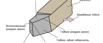
Image #1: Lathe cutter design
Cutting planes
The angular parameters of a cutting turning tool are calculated using a system of coordinate planes, among which the basic planes are the main plane, the cutting plane and the main secant plane. Their mutual inclination forms the sharpening angles of the cutting part, ensuring turning in design modes. In this way, the following angles are determined: the main front (γ), the main back (α), the sharpening angle (β), as well as a number of other angles.
Cutter angles
The operation of a turning tool during the cutting process is determined by the angular parameters of the front and rear surfaces. Therefore, the main angles of the incisor are the main anterior (γ) and the main rear (α). By increasing the first, power consumption for cutting is reduced, chip control is improved and roughness is reduced. On the other hand, as the rake angle increases, the thickness of the blade decreases, which leads to a deterioration in its strength characteristics, increased chipping and a decrease in the rate of heat dissipation. The main purpose of the clearance angle is to reduce friction between the cutting surface and the main clearance. In addition to the main functional angles α and γ, the calculation determines several more angles, whose values affect the class of turning cleanliness, the process of chip formation and other technical characteristics.
Depending on the purpose
Here we are most often talking about the materials being processed.
For wood
Woodworking tools are sold by stores in the following sets:
- Combs.
- Rings.
- Hooks.
- Oblique incisors.
- Trimming cutters.
- Chisels.
- Reiers.
- Meysel.
The cutters and rotary mechanisms are attached to each other. Traces of workpieces are determined immediately by the tools, their shapes, strength, and sharpness. This makes it easier to select the shapes of the blanks in the end. From
When choosing specific sharpening angles, they rely on the materials of the workpieces.
For working with metal
Welding and brazing of plates is the optimal choice for cutters that process metal. In production, preference is given to high-speed, hard alloys. The compositions usually contain tantalum or tungsten, titanium. High strength and affordable price have become the main advantage for the tools.
Varieties are often used in which the plates are replaceable. Then they are attached to the head using special screws or clamping elements. Mineral ceramic plates are the most convenient for further use. But then the cutter will be expensive.
Carbide alloys are used in the case of tool working surfaces:
- Tungsten.
- Titanium tungsten.
- Tantalum-tungsten-titanium.
Options with high-speed steel or its carbon variety are acceptable.
Installation of cutters is permissible on several types of machines:
- Special purpose.
- Revolving automatic.
- Slotting.
- Lathes.
- Planing.
By type of processing
Finishing
Feed at low speed. The material, which is characterized by a small thickness, is removed from the blank. A pass-through cutter is the most popular type of such tool.
Semi-finish
Many similarities with the previous variety. Only the characteristics they use are two times smaller compared to the analogue. The purpose and features of the work remain almost the same.
Types of cutters for a lathe and their purpose
When describing the types of turning tools, several classifying characteristics are usually used. According to its design, it is divided into two types: solid and prefabricated. In the first case, the entire product is made in the form of a monolithic bar of metal. And in the second, removable or soldered carbide plates act as the blade. According to their technological purpose, turning cutters are divided into special ones, which are used for processing various profiles and threading, and general purpose products, used for external and internal turning, cutting and end trimming. Another distinguishing feature of a turning tool is the configuration of the cutting part, which depends on its operating modes and the type of turning work. For turning hard-to-reach places, a curved cutter is usually used, which has several varieties, differing in the length of the cutting part, the shape of the bend, sharpening and purpose (cockerel, bent, reverse cutters and others).
Another classification option is the division of turning tools according to the principle of machining cleanliness. There are usually two classes here: rough and finishing. The first is intended for roughing or pre-turning operations, and the second is for finishing operations. If the rough tool, with rare exceptions, is quite the same type, then among the finishing tools there are a number of varieties with their own names. Examples include blade and radius cutters with an arcuate blade, the purpose of which is precise finishing turning. Another separate type is a diamond cutter, used for turning work on super-hard materials. A cup turning cutter with a circular cutting surface has a unique design that can work for a long time without regrinding.
In addition to the standard classification, there are many names for specific turning tools, usually reflecting the features of its design or technology of use. These include a spring cutter with a wave-shaped cutting part, which springs during turning of hard and uneven materials.
A separate category of cutting tools for lathes are planing cutters. During turning operations using them, feed is carried out on a stationary part. In this case, the allowance is not cut off, as during rotation, but is removed by planing. In this configuration, a lathe performs the same function as a planer or slotter.
Direct passes
Used for external processing of steel workpieces.
A pass-through turning cutter with a part fixed in a square-section caliper. Used when carrying out special piece operations.
Bent pass-throughs
Special equipment in which the working part is bent to the left or right. Used for trimming parts. With their help it is convenient to remove chamfers.
Thrust pass-throughs
Devices come with a straight and bent working element. Designed to work with cylindrical parts. The shape plus proper sharpening allows you to quickly remove most of the excess from the working surface of the workpiece.
Bent edges
They are equipment similar to a walk-through. However, there is a difference in the shape of the cutting edge. It is triangular, which allows for better processing.
Boring
Used for through and blind group holes, recesses, and recesses.
Threaded
They create carvings outside and inside, with a section in the shape of a trapezoid, rectangles and circles. Products can be smooth, convex or round.
For external thread
They are made of durable alloys (hardened steel, cermets), spear-shaped, allowing you to apply metric and other helical spiral lines of the required depth. Available in the three most common sizes: 25 by 16, 16 by 10 and 32 by 20 mm (the latter are relatively rare in use).
For internal thread
Relevant only for those parts that have technological holes of large cross-section. The main design feature is the presence of a serpentine head. The holders boast a significant length, necessary for the tool to penetrate deeply and carefully into the fixed workpiece during the operation. Suitable only for equipment that is equipped with a “guitar”. Their dimensions, in millimeters:
- 16 x 16 x 150;
- 20 x 20 x 200;
- 25 x 25 x 300.
Smooth
They differ from the previous version by maintaining rectangular edges.
Prefabricated
The working part of the cutter 1, into which the pin 3 is seated, a carbide plate 2 is put on it. It is secured with a wedge 5 and a screw 4. This way it is securely clamped in the cutter body.
The plates are produced in 3, 4, 5 and 6-sided versions. Advantages: reduced time for processing the part, good chip removal. Instead of sharpening, they rotate the plate.
The blades are cheaper than a whole chisel. You can place plates from different alloys on one holder in turn. Optimal for fine turning.
Geometry of turning tools
Image: geometry of a turning tool.
Let's talk about the angles of the incisors and their purposes.
- Back auxiliary angle (α1). As it decreases, the friction force between the rear plane of the tool and the workpiece decreases.
- Apex angle (ε). Formed between the cutting edge and the rear auxiliary plane. The larger this angle, the better the heat removal conditions and the higher the strength of the cutter.
- Auxiliary plan angle (ϕ1). Its size varies from 10 to 30°. As the angle decreases, the cleanliness of the treatment improves, but the friction force increases.
- Leading angle (ϕ). Its size varies from 20 to 90°. The length and width of the cut depend on the size of the angle. The smaller ϕ, the lower the temperature and cutting force. The cleanliness of the processing is also improved. But as the angle decreases, vibration and radial cutting force increase.
- Cutting angle (δ). Formed between the rake surface and the cutting plane.
- Basic rake angle (γ). Its size varies from -5 to +15°. As the angle increases, it is easier for the tool to cut into the metal, chip removal is improved, and the cutting force, deformation of the machined surface, and power consumption are reduced. However, this reduces heat dissipation and reduces the service life of the cutting edge.
- Taper angle (β). Formed between the front and main back surfaces. Affects the sharpness and strength of the tool.
- Main relief angle (α). Its size varies from 6 to 12°. As the angle decreases, the friction force between the part and the back surface of the cutter decreases. This improves heat dissipation and extends the service life of the tool, but the cleanliness of the machined surface deteriorates.
- Angle of inclination of the main cutting edge (λ). Affects the direction of chip removal. At positive λ and λ = 0°, the chips move towards the machined surface. Cutters with positive λ (12–15°) are used when processing workpieces made of heat-resistant and hardened steels. For universal turning tools, λ = 0°. Cutters with negative λ are used for finishing.
Marking of turning tools, meaning of numbers and symbols
According to the standard, the marking of turning tools may include 9 or 10 characters.
- The first is the method of attaching the cutting insert.
- The second is its shape.
- The third is the type of cutter.
- The fourth is the rear corner of the cutting insert.
- Fifth - cutting direction.
Image No. 6: possible values of parameters 1–5
- The sixth is the height of the holder.
- The seventh is the width of its tail section.
- The eighth is the total length of the incisor.
- The ninth is the size of the cutting plate.
Image No. 7: possible values of parameters 6–9
- The tenth is indicated if necessary. Indicates the accuracy of some cutter parameters.
Image No. 8: possible values for parameter 10
Cutters for lathes - what to look for
When choosing this metal-cutting tool, you need to pay attention to the following basic parameters:
- material and geometry of the cutting part;
- chip breaking method;
- strength and vibration resistance of cutting edges and holder;
- shape and dimensions of a removable or welded plate;
- geometry, design and roughness of the plate socket;
- durability and dimensional stability of the cutter;
- cutter angles;
- ensuring the specified roughness of the processed surface.
To get a consultation
regarding tools, processing methods, modes, or select the necessary equipment, you can contact our managers or CAD department
You can also select and purchase cutting tools and equipment for the machine, made in Taiwan, Israel
By submitting an application, you agree to the privacy policy
Turning cutters are the main working tool of wood and metalworking machines, through which the processed workpieces are given the required shape and size. The classification of turning cutters is carried out according to factors such as purpose, type of processing, method of feeding and fastening, which we will discuss in more detail in this article.
The publication discusses the types of turning cutters and their design, provides recommendations for choosing a tool and the technology for its installation, and also provides instructions by following which you can properly sharpen the cutter with your own hands.
Marking according to GOST
Requirements for the production of metalworking machines, as well as auxiliary equipment, are strictly regulated by the requirements of interstate standards.
There are much fewer requirements for the rods of cutting devices compared to the elements of the contact group. They are made from steel grade 45 or 50.
There is a separate standard for each type of design. For example, the production of cutters with upper clamping of a replaceable plate is regulated by GOST 26611-85.
In the production of high-speed steel plates, cobalt compounds are used:
- R9K5;
- R9K10;
- R18F2K5.
After heat treatment, their hardness reaches 67 HRC.
There are special requirements for the surface roughness of devices. After finishing the front and rear parts, the degree of cleanliness must correspond to class 9.
Symbols in accordance with the requirements of the interstate standard are applied to the side surface.
As an example, let's decipher the T15K6 marking:
- "T". The first letter indicates that a solid composition of the titanium group was used as the manufacturing material.
- "15". The number indicates the mass fraction of titanium carbide in the product.
- "TO". The product contains cobalt.
- "6". Mass fraction of the above chemical element.
Tool classification
There are many parameters for classifying cutters in accordance with current GOSTs. According to the design features, the following types of turning tools are distinguished:
- monolithic, in which the cutting head and holder are a solid structure;
- prefabricated ones, in which a high-speed alloy plate is soldered on the head, providing increased processing efficiency - this is one of the most common types of tools;
- prefabricated, with a mechanically fixed plate - the plate is fixed on the head by a bolt; in this configuration, cutters with metal-ceramic plates are made;
- adjustable.
Functionality of cutters
Depending on the quality of processing, turning tools are divided into roughing and finishing. The geometry of the roughing tool allows for the removal of thick material and maintains hardness under the intense heat that occurs at high processing speeds. Finishing analogues have a different purpose; they are needed to work at low speeds to remove a small thickness of material.
The tool is also classified according to the feed direction, according to which right and left cutters are distinguished. The feed direction refers to the side on which the main cutting edge of the tool is located at the moment when its head is facing the front of the workpiece.
Types of incisors
Functional purpose is one of the main classification parameters of this tool. According to their purpose, turning tools are divided into:
- Cutting (GOST No. 18874-73) - used on machines with transverse feed of working tools, intended for sheathing and processing of the end parts of workpieces.
- Pass-through (GOST No. 18871-73) - can be installed on machines with both transverse and longitudinal feed. They are used for trimming ends, turning, forming parts of conical and cylindrical shapes.
- Cutting, also known as groove (GOST No. 18874-73) - mounted on machines with transverse feed. Used for cutting monolithic pieces of metal and turning ring-shaped grooves.
- Boring (GOST No. 18872-73) - designed for boring holes (through and blind), forming recesses and recesses.
- Shaped (GOST 18875-73) - used to remove external and internal chamfers.
- Threaded (GOST No. 18885-73) - allow you to cut threads of metric, inch and trapezoidal sections (both internal and external).
Also, turning cutters are divided into straight, bent and drawn depending on the position of the cutting edge in relation to the holder. In bent ones the edge is made in the form of a straight line, in bent ones it is curved, in drawn ones the edge is narrower than the width of the rod.
Which cutters to choose, where to buy?
To determine which cutters are needed specifically in your case, you need to decide on the following points:
- what metal you will process and what operations will be performed;
- prioritize quality, processing efficiency and tool wear resistance.
In general, a novice turner needs to have three types of cutters at his disposal: passing (marked SDACR) - for processing ends, external neutral type (SDNCN) and boring (SDQCR). This is a basic kit that allows you to perform most technological operations.
If you are interested in buying a tool for long-term use, it makes sense to buy a set of turning tools with replaceable inserts. Subsequently, you will be able to change consumables rather than buy new holders after the cutting head wears out.
A few words about the manufacturers. Among the companies that sell really high-quality products that are worth buying, we highlight the companies Hoffman Garant (Germany) and Proma (Czech Republic). In the segment of domestic manufacturers, the companies SiTO (Gomel Tool Plant) and Kalibr deserve attention. You can order cutters with delivery using the links provided.
It also makes sense to purchase a sharpening machine that will allow you to return the cutters to their functionality when worn out yourself, rather than using the services of third-party craftsmen. Here you need a sharpening and grinding unit equipped with a constant cooling system with two abrasive wheels - made of silicon carbide (for cutters made of high-speed alloys) and electrocorundum (for carbide tools). When sharpening, it is initially necessary to process the front plane of the cutting head, then the additional and rear ones, until a smooth cutting edge is formed.
Lathe cutter design
The basis of the cutter is a rod fixed in the cutter holder. A cutting element, the head, is installed in the front part of the rod. The cutter has several surfaces. Chips run off the front surface. The rear surfaces, main and auxiliary, face the part. The main cutting edge, lying at the intersection of the front and main back surfaces, cuts the metal.
Classification of incisors
Turning cutters differ:
- In the direction of delivery. The right cutters move during the working feed from the tailstock to the front (from right to left). The left is making the opposite labor movement.
- According to the type of working head: straight, bent incisors.
- Turning cutters are produced as one-piece and composite ones. The compound cutter is made with an attached head made of expensive steel.
- According to the geometric section of the rod.
The cutting part of turning tools can be made of carbon and carbide steels (“Pobedit”), diamond and mineral-ceramic materials.
Determining the working direction of the cutter is simple. When installing, the cutting edge should be directed towards the workpiece.
Types of turning tools
Walkthroughs. Used for processing external cylindrical surfaces. Performed for working passage in both directions. A bent cutter can process ends during transverse feed.
Passing persistent. They are used to process stepped parts and trim the ends. Such cutters ensure perpendicularity of adjacent planes of steps. Can be either right or left. They are made of hard alloys by soldering onto a rod.
Trimming. They machine the stepped profile of a part, trim the ends and beads, and are capable of processing external cylindrical surfaces. The carbide cutting part is made by soldering onto the base.
Boring. The diameter of the holes prepared by drilling is increased (bored). Boring is carried out in several stages with the formation of a stepped surface at the end. Then, using a cross feed, the steps are cut until perpendicular surfaces are formed.
Cut-off. The finished part is separated from the workpiece, grooves and grooves are machined. Processing is carried out at right angles to the part with a working part made of high-speed and hard alloys.
Cutting internal and external threads is carried out using thread cutters . Shaped sharpen surfaces of complex shapes and grooves.
Automatic turret cutters
They are used on automatic turret lathes in mass production.
Longitudinal turning cutters. Automatic cutters made of high-speed steel are made by soldering or mechanically attaching the cutting part to a rod. The tool, depending on the installation in relation to the part, can be radial or tangential, which is ensured by special sharpening, as well as the design of the holder installed in the turret. By rotating the holder, the cutters are installed at different angles in relation to the workpiece.
Read also: How to cut a mirror with an angle grinder
Grooving and parting cutters. Installed on transverse supports of automatic machines. They have a design similar to cutters for conventional lathes. Since automatic machines mainly work with bar blanks, the cutting cutter, having a specific sharpening, not only cuts off the finished part, but also processes the end of the next part.
Making your own cutters: a step-by-step guide
The main thing is to use only tool steel that has sufficiently high performance characteristics.
Experts recommend choosing an alloy or high-speed carbon version.
Selecting the required configuration of files or rasps
The selection of these parts will be easier if the owner knows in advance exactly what tasks he faces. After this, choosing the length, shape and size will not be difficult. Here are some tips.
- If you need to file up to 5-10 mm in thickness, it is better to stop at cut number 0 or 1.
- The processing accuracy should be within 0.01-0.02 mm.
- It is much easier to choose devices based on length.
The main guideline is the dimensions of the surface that needs to be sawed. The larger this parameter, the larger the device itself should be.
You can use a specific formula to make the calculation more accurate. We add 15 cm to the length of the surface of the product. We get the value, which will be the length of the working surface of the file or rasp. The main thing is that when working, the tool is passed over the entire workpiece.
Fastening cutting parts
Homemade tools do the same as professional ones. The optimal solution is self-tapping screws. The higher quality the product, the better.
How to install a parting cutter
In order to perform cutting correctly without increased wear of the cutting plate, as well as to ensure the required quality of the end after cutting, it is necessary to align the cutter strictly perpendicular to the part. In addition, it must be installed opposite the axis of rotation with a vertical deviation of no more than ± 0.1 mm. Placing the edge of the blade even a few tenths of a millimeter higher can cause the cutting blade to break, and placing it too low can leave an uncut step on the workpiece. Cutting must be done as close to the chuck jaws as possible, using a cutter with a minimum overhang.
To facilitate the processing of complex materials on desktop machines, spring and inverted cutters are used. But, probably, craftsmen use other designs for these purposes, as well as various improvements to “standard” cutters. If you know anything about this, please share information in the comments to this article.
Cutting modes
Cutting modes are a set of parameters that determine the conditions for processing parts using a turning tool. The cutting process is influenced by the following factors:
- Cutting speed is the path of movement of the machined surface of the workpiece relative to the cutting edge per unit time. Measured in m/min or m/s. In the drawings it is designated by the Latin letter V.
- Feed is the path traveled by the cutting edge in 1 stroke or revolution of the workpiece being processed. Measured in mm/rev. In the drawings it is marked with the Latin symbol S.
- Depth of cut is the distance between the machined and machined surfaces. It shows the amount of metal layer being removed. In the diagrams it is denoted by the Latin letter t.
- The cross-sectional area of the cut layer is the product of the cutting depth and the feed. It is a nominal value and affects the presence of roughness. In the diagrams it is indicated by the Latin symbol f.
These parameters are tabular values and are specified in GOST 25762-83.
Download GOST 25762-83
Each type of cutting tools with mechanically fastened inserts has additional cutting modes. Cutting cutters carry out transverse movements, boring tools move longitudinally relative to the surface of the workpiece. During operation, the average speed of the cutting edges is tenths of mm. The feed is 0.1 mm/rev.
Operating rules
Turning cutters are capable of performing their main function for a long time until the working surface is ground down. But improper use will shorten the life of the tool. To prevent preliminary wear, you need to follow simple operating rules:
- Install centrally.
- The larger the dimensions of the workpiece, the larger the cutter should be.
- Turn on cooling when operating in heavy conditions.
- Sharpen in a timely manner.
- Periodically polish the working surfaces with a fine-grained stone without removing the tool from the tool holder.
- Apply the tool to the workpiece manually, and after touching, turn on the automatic feed.
- When stopping the machine, first manually retract the tool, then turn off the unit.
- Select the correct cutting modes.
- Do not store the tool in a pile - this will lead to chips and cracks on the cutting edge.
- When working with a cutting tool, bring it as close to the chuck as possible.
Many types of work are performed on a lathe. A separate cutter is provided for each process. It is selected based on the material being processed, cutting conditions, cleanliness and roughness parameters. The tool must be sharpened in a timely manner, and the rules of operation and storage must be followed.
Advantages and disadvantages of incisors
Thread cutters with replaceable inserts have the following advantages:
- low cost: cost less than solid type incisors;
- allow you to save a large amount of time resources during the preparation of cutting tools for various technological operations;
- the plates are able to withstand high loads because they are made of carbide materials;
- cutting cutters can be used to process parts with small dimensions and uneven terrain;
- the cutting tool can be readjusted if necessary;
- high service life of the holders, which allows the tool to be firmly secured to the lathe;
- do not require additional sharpening or soldering;
- during processing, reduce cutting force and temperature by 35 - 40%;
- provide the ability to change cutting modes on the fly;
- unification of all cutter models: allows you to select the right insert for processing workpieces made of certain types of metals.
Experts highlight the following disadvantages of cutters with replaceable inserts:
- due to the presence of many fasteners for carbide inserts, the total weight of the cutting tool increases;
- cutters are not able to provide optimal geometric parameters of the cutting edge due to the different shapes of the plates and the peculiarities of their fastening;
- high complexity of manufacturing cutting tools.
The quality of a thread cutter depends on the type of processing and cutting mode. The cutter retains its benefits longer at low cutting speeds and during internal cross turning. The cutting tool wears out faster during external longitudinal turning. To increase its durability, lubricating and cooling media are used. You can also increase the rigidity of the tool by increasing the area of the holder.
Sets of cutters with other parameters
Cutters for a metal lathe 8x8 mm from the Czech company Proma are represented by eleven tools. By means of soldering, they are equipped with carbide plates. The cutter sizes in this set are 80 mm and 125 mm.
Those who need a tool with a tail section of 0.12 cm for work can use cutters for a 12x12 mm metal lathe. A wide range of work can be performed using the following cutters:
- pass-through bent;
- persistent;
- threaded;
- boring;
- cutting;
- slotted and other types of cutters.
In the modern tool market, a wide range of different products for metalworking equipment is available to the consumer. For a beginner who has decided to purchase a set of cutters for a metal lathe, experts recommend that they familiarize themselves in detail with the classification of these tools, carefully study their design features and characteristics, so that they do not have to regret their purchase in the future.