Correct operation of the Makita 2450 rotary hammer with a commutator motor is accompanied by slight sparking of the brushes in the commutator area. A properly functioning electric motor has a uniform spark with a short tail.
By changing the sparking pattern, you can determine the nature and location of the malfunction in the Makita 2450, 2470 hammer drill.
The reasons for the increase in sparking in the electric motor commutator may be faulty brushes and their wear, short circuit or armature breakage, malfunction of the stator windings of the electric motor, breakage or improper fastening of brush holders.
Significant sparking in the commutator area leads to the appearance of grooves on the commutator, burning of the plates, and uneven abrasion of the brushes.
The occurrence of the listed defects causes rapid wear and wear of the lamellas of the collector itself.
Roughness is higher than normal
Since a hammer drill is a powerful tool, small sparks are allowed without load; with significant effort on the tool, single sparks may run in a circle. In case of strong sparking, it is necessary to find out the reason for the strong sparking.
The most common fault on the commutator is the increasing roughness of the lamellas with increasing sparking of the brushes.
An increase in the surface roughness of the Makita 2450 rotary hammer commutator occurs not only due to increased sparking. Copper oxide forms on the copper plates of the commutator; its hardness exceeds the hardness of the carbon brushes. The amount of roughness is affected by uneven wear of brushes and carbon deposits from sparking.
Scratches are formed not only due to uneven wear of the brushes and different structure of the material, but also due to the entry of solid particles from the air into the working area.
Improper storage of a Makita rotary hammer can lead to the appearance of oxide on the copper plates of the collector due to high humidity or significant temperature changes during operation.
To eliminate defects on the surface of the collector, it must be sanded.
How to properly sand the surface of the commutator
Before you begin to modify the manifold of the Makita 2470 rotary hammer, you must balance the rotor.
Option for measuring the runout of the commutator relative to the rotor
At home, grinding the manifold of a Makita 2450 or 2470 rotary hammer is best done with sandpaper attached to a wooden block already on a balanced rotor.
The end of the rotor shaft is secured in the drill chuck through soft copper or aluminum foil. A drill with a rotor is securely fastened in a vice or homemade device.
While rotating the rotor, try to center it in the drill chuck.
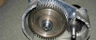
Installing the rotor into the chuck
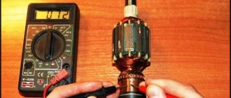
Checking the commutator motor with a multimeter
Let's say a visual inspection did not produce results - at first glance, all components are intact, no breaks were found, and there is no burning smell. In this case, check the device and its elements using a special device - a multimeter. The process consists of several stages:
- Set the device to resistance measurement mode up to 200 Ohms.
- Ring the paired terminals of the stator windings on the lamellas. The resistance values must be the same.
- Check the armature body and lamellas. Ideally, the resistance value tends to infinity.
- Ring the winding terminals. If there is no resistance in one or more circuits, the motor is faulty.
- Check the circuit between the stator housing and the winding terminals. If there is a breakdown in the housing, operation of the unit is impossible.
- Ring the rotor by placing the tester probes on the commutator at the maximum distance from each other. When the multimeter shows a value, turn the rotor slightly until the probes connect to the next winding. Check all windings in this way. If the resistance value in each circuit is the same or differs very slightly, the unit is working.
You should not immediately take a “jammed” device for repair or throw it away, as many people prefer to do. You will save money if you know how to restore the electric motor commutator yourself. The process is not too complicated and does not take much time, and the mechanism can last for a long time.
Equipment is often subject to overloads and mechanical damage. Once you drop or spill something on the tool, rust appears on the rotor winding, and the armature itself moves. The consequences are dire: the electric motor overheats, sparks and vibrates. Working with such a tool is dangerous.
If you have the skills to repair equipment and a minimum set of tools, then rewinding the armature at home will help fix the problem. The fact is that it is the winding that takes the first “blows” of improper operation. The conductor strands are torn and burned. Replacing them will extend the life of the equipment and increase engine performance.
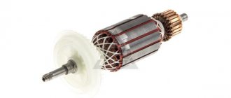
How to center the rotor in a drill before grinding
The rotor is centered in the drill chuck to ensure minimal runout of the radial surface of the commutator relative to the rotor shaft.
First check the runout of the chuck jaws. Secure the drill in a vice, install a drill of the largest diameter in the chuck.
While rotating the drill, bring a pencil to the rotating side surface of the drill, resting it on a simple stop. With minimal runout, the pencil will draw a solid line on the surface of the drill. If the runout is significant, change the chuck in the drill or select a drill with less chuck runout.
Now, instead of a drill, clamp the rotor shaft and in the same way determine the runout locations of the rotor or commutator.
Preliminary check of the commutator motor
If the device does not work, first make sure that the problem lies with the motor itself. For this:
- Check if there is voltage to the device. Plug it into another outlet (the power source may need repairs).
- Inspect the cord for breaks.
- Check if the contact of the power and control buttons is lost, if there is any mechanical damage.
If there are no problems with these parts, disassemble the device. Use the instructions that the manufacturer necessarily includes in the passport.
Commutator grinding process
The process of grinding the collector must begin with the selection of sanding material. It is recommended to use sanding paper or a file to sand the commutator.
Choose several sizes of sanding paper, starting from #100 and above.
Now start sanding. Applying a wooden block with sandpaper attached to the commutator, rotate the drill and, without pressing the block too hard to the surface of the commutator, grind.
Grinding the commutator in a drill
It is recommended to use the grinding operation on already operating rotors with minor wear on the commutator.
Proper brush sparking
If you have replaced the commutator on the rotor of the Makita 2470 rotary hammer, then after installing it on the shaft, the commutator must be machined. This operation is performed to eliminate radial runout of the surface of the lamellas of the new collector relative to the armature shaft.
It is best to grind the manifold on a lathe using mandrels. But this operation can also be performed at home. True, you can’t do it without an additional device. The video will help you understand the manifold groove.
As a rule, brush holders on hammer drills are mounted opposite each other. Prolonged operation of the brushes leads to the formation of grooves on the collector, creating waviness on the surface. Such wear can only be eliminated on a lathe by turning the commutator.
To reduce the formation of grooves on the commutator, you should try to arrange the brush holders in a checkerboard pattern.
Wire winding
There are several ways to rewind the stator of an asynchronous electric motor, but when choosing any of them, be sure to remember each step during disassembly. This will make the repair easier, and significantly. For winding, you will need a copper wire in varnish insulation; its cross-section should be the same as on the electric motor being repaired.
Make sure that there is no damage to the housing and magnetic circuit of the electric motor. After this, it is necessary to make sleeves and install them in the grooves on the stator. In order not to count the number of turns, or to determine the thickness, strength and heat resistance of materials for the manufacture of sleeves, you can use reference literature. To do this, you need to know the type and model of the asynchronous motor.
All work in specialized workshops is carried out on machines. The machine even calculates the number of turns. But how can you rewind an electric motor at home if there are no such conditions? You will have to calculate everything yourself, or take all the data from the service book for the electric motor.
How to check the condition of the brushes
When installing new carbon brushes, it is recommended to grind them in for a better fit to the commutator surface.
It is best to adjust carbon brushes using a homemade grinder. The lap is a shaft on which sandpaper is attached. The easiest way is to make the shaft from wood with a diameter equal to the diameter of the commutator, turning the workpiece on a lathe. A metal rod is inserted tightly along the axis inside the shaft. The device is attached to the chuck of an electric drill, the drill is turned on, and the brushes are brought to a rotating emery wheel.
The adjustment should be carried out carefully, periodically applying the brushes to the rotor commutator to check their clearance.
Having ground the brushes to the commutator, it is recommended to check the correct fastening of the brush holders before installation. When factory installed, the brush holders are set to neutral, which minimizes sparking on the commutator. If there are no factory marks, then the installation of the brush holders is adjusted by moving the brush holder in the direction opposite to the rotation of the rotor until a minimum spark is formed.
The brushes should not dangle in the brush holder, but should be pressed tightly against the commutator lamellas. The pressing force is regulated by springs in the brush holder.
Sparking faulty collector
An increase in sparking on the rotor commutator may appear due to a short circuit of the armature, a break in the armature coils, or a short circuit of the windings to the armature body. All these faults can be eliminated only with a major overhaul of the rotor.
Major and current repairs
Repair of electric motors is always in demand, because motors are widely used in all areas of life. Inspections of units are carried out in the form of routine and major repairs.
Current repairs include inspection, oil change, and measurement of various standardized values and indicators. The period of current and major repairs is established in the rules. Current repairs are carried out once every two years, major repairs are carried out once every 5 years.
Advantages of electric motor overhaul:
- It is more economical to repair than to buy a new one;
- repair time is less than the delivery time of a new unit;
- specific units may go out of production.
Features of the asynchronous motor of the angle grinder
Almost all electrical appliances used in everyday life use an asynchronous electric motor. An important advantage of this type of motor is that when the load on it changes, the speed does not change. This means that if, for example, you cut stone for a long time and without stopping with a household grinder, there will be no noticeable external signs of engine overload. The disk rotation speed will be constant, the sound will be monophonic. Only the temperature will change, but this may not be noticed if your hands are wearing gloves.
If you are not careful, an advantage can turn into a disadvantage. Asynchronous motors are very sensitive to overheating; a significant increase in operating temperature entails melting of the insulation on the rotor windings. At first, the motor will work intermittently, and then - when an interturn short circuit occurs - the motor will stop completely. If you overheat the grinder's engine several times, it is most likely that the anchor will melt. In addition, the high temperature causes the contacts connecting the wires of the primary winding to the collector to become unsoldered, which leads to an interruption in the supply of electric current.
Main causes of breakdowns
The most common causes of electric motor breakdowns are improper operation and aging of parts. Electric motor faults are divided into two types: mechanical and electrical.
There is a list of the most common breakdowns that occur with electric motors in various household appliances and appliances.
- Faulty fan. The motor is under acceptable load, but the stator is overheating.
- The rotor touches the stator. In this case, the steel overheats greatly.
- Violation of normal ventilation of the electric motor. The stator winding overheats.
- Intense current pulsation in the stator.
- Poor contact in the rotor chain.
- The fuse overheats, the electric motor does not start.
- Broken stator winding.
- Strong heating of brushes and commutator, sparking.
- Destruction of raceways. Extraneous noise is heard in the bearings.
Increased vibration. May occur due to the rotor and couplings being unbalanced.
How to determine if an angle grinder's armature is faulty
Signs of a broken armature angle grinder are: increased sparking of the brushes on the motor commutator, vibration of the motor at low speeds, rotation of the working shaft in different directions. If such symptoms are present, you should stop using the tool - this is dangerous. Suspicions can be easily verified using simple tests.
Visual inspection from outside
Troubleshooting should begin with a visual inspection of the angle grinder:
- Carry out a general inspection of the instrument.
- Pay attention to the integrity of the power cord and the presence of voltage in the outlet.
- Using a voltage indicator, make sure that current is flowing to the motor commutator and the start button.
Inspection of the device from the inside
If everything is in order with the power supply, but the angle grinder does not work, you will have to open the case to gain access to the motor. As a rule, disassembly is not difficult. But you need to follow simple rules that will help you avoid troubles during reassembly:
- Be sure to disconnect the device from the mains before disassembling.
- Remove the working disk and protective cover from the spindle.
- Open the case in a well-lit place, on a clean table surface.
- Remember the location of all parts and assemblies before disassembling. It is recommended to sketch or photograph the internal structure of the device.
- Place screws and fastening screws in a separate place so that they do not get lost.
It is best to inspect the engine under bright lighting so that all small parts are clearly visible. The armature should rotate freely around its axis; properly functioning bearings should not make any sound during operation. There should be no traces of melted wiring on the armature, the circuit windings should be intact, without breaks. You can smell the rotor. When there is an interturn short circuit, the insulating varnish burns and emits a persistent specific odor. But such a diagnosis requires some experience.
Continuity testing of circuits with a tester
If a visual inspection does not give clear results, it is recommended to continue the examination using a multimeter. Having set the mode switch to the ohmmeter position (200 Ohm range), you need to “ring” two adjacent armature lamellas with two probes. If the resistance on all turns is the same, this means that the windings are working properly. If on some pairs the tester shows a different resistance or an open circuit, there is a malfunction in this coil.
Motor protection options
There are various devices that provide additional protection for the engine and minimize damage.
- Thermal relays and automatic motors. They reliably protect the electric motor from damage due to excess current.
- Electronic relays. It is a microprocessor that analyzes the voltage value.
- Thermal relays and thermistors. They help avoid breakdowns when the thermal protection does not work due to overheating.
- Frequency converter. It carries several functions related to overload protection.
In what cases can you save an anchor and restore it yourself?
If damage to the armature is determined with guaranteed accuracy, the part must be removed from the electric motor. Disassembling the motor must be done with special care, after removing the brushes and disconnecting the power terminals. The rotor is removed along with the support bearings and the motor cooling impeller; they form a single whole with it.
If most of the wiring in the armature is damaged and the balancing is disrupted as a result of overheating, it is better to replace it entirely. An imbalance is indicated by increased vibration and an uneven hum when the mechanism operates.
How to rewind an anchor - step-by-step instructions
If the balancing of the armature is not disturbed, and the problem is only in damaged windings, then such an armature can be restored independently by rewinding the coils. Rewinding a rotor at home requires a lot of patience and accuracy.
The technician must have skills in working with a soldering iron and instruments for diagnosing electrical circuits. If you are unsure of your abilities, it is better to take the engine to a workshop for repairs or replace the entire armature yourself.
To rewind the anchor yourself you will need:
- wire for a new winding. A copper core with a diameter exactly matching the old conductor is used;
- dielectric paper for insulating the winding from the core;
- varnish for filling coils;
- soldering iron with tin-lead solder and rosin.
Before rewinding, it is important to count the number of turns of wire in the winding and wind the same amount of new conductor onto the coils.
The rewinding process consists of the following steps:
- Dismantling old windings. They must be carefully removed without damaging the metal body of the armature. If any burrs or damage are found on the body, they must be smoothed out with a file or sanded with emery. Sometimes, to completely clean the body of slag, craftsmen prefer to burn it with a torch.
- Preparing the collector for connecting a new wire. There is no need to remove the manifold. You should inspect the lamellas and measure the resistance of the contacts in relation to the housing with a megger or multimeter. It should be no more than 0.25 MOhm.
- Removing old wiring on the manifold. Carefully remove the remaining wires and cut grooves in the contacts. In the future, the ends of the coil wires will be inserted into the grooves.
- Installation of sleeves for anchors. The sleeves are made of dielectric material 0.3 mm thick, for example, electrical cardboard. Cut a certain number of sleeves and insert them into the grooves of the cleaned anchor.
- Rewinding reels. The end of the new conductor is soldered to the end of the lamella and wound in successive circular movements, counterclockwise. This laying is called “laying to the right.” Winding Repeat for all coils. Near the collector, tie the wires together with a thick thread of cotton fabric (it is prohibited to use nylon, as it melts when heated).
- Checking the winding quality. After laying all the windings, check with a multimeter for the absence of interturn short circuits and possible breaks.
- Finishing processing. Treat the finished coil with varnish or epoxy resin to secure the winding. In factory conditions, the impregnation is dried in special ovens. You can do this at home in the oven. As an option, use quick-drying varnishes for impregnation, applying the coating in several layers.
Stator in different types of electric motors
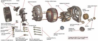
The stator is an integral component of an electric machine that remains stationary while the engine is running. The rotor is the rotating part of an electric motor that transmits mechanical energy to the output shaft. Another name for a rotor is an armature.
Synchronous or commutator motor
Electric current is transmitted to the commutator lamellas by graphite brushes. Such an electric motor will operate in both direct and alternating current networks. The pulsating magnetic field generated by the stator windings will interact with the pulsating magnetic field generated by the armature windings. The rotor will begin to rotate. Such electric motors are widely used in various household and industrial appliances: electric drills, vacuum cleaners, power drives of machine tools, and electric vehicles.
Interesting. Motors of this type have another name - synchronous. This means that the rotation speed of the rotor is equal to the rotation speed of the electromagnetic field arising in the motor.
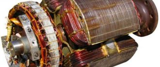
Asynchronous motors
The overwhelming majority of electric motors used both in industry and in everyday life are asynchronous electric motors with squirrel-cage rotors. Such motors are used in three-phase and single-phase AC networks.
Asynchronous motor
The stator structure is assembled from a large number of steel plates and is located in a base housing cast from non-magnetic metals: cast iron or aluminum.
Stacked motor stator
Plate material – electrical steel. The plates are insulated from each other with a special dielectric varnish. The stator has longitudinal grooves where three windings are placed, shifted relative to the axis of rotation of the electric motor by 120 degrees from each other. The rotor is also made of insulated electrical steel plates. Rods made of aluminum, less often copper, are placed in the grooves of the rotor, connected at the ends by slip rings. Hence the name - squirrel-cage rotor. This design, called a “squirrel wheel,” plays the role of a rotor winding.
Below is a cross-sectional view of an asynchronous electric motor. You can clearly see what a stacked stator is.
Sectional view of an asynchronous motor
The motor windings can be connected to a three-phase electrical network in a delta or star configuration.
Three-phase motor connection options
The circuit is switched in the motor terminal box, called born or brno.
When three-phase voltage is applied, pulsating currents arise in the stator windings, which cause the appearance of a rotating magnetic field in the stator. This field crosses the conductive rods of the rotor, in which secondary pulsating currents are induced. The result is the appearance of a magnetic field in the rotor. The magnetic fields of the stator and rotor interact and cause the rods of the “squirrel wheel” to rotate, along with the rotor itself. The armature rotates at a speed slightly lower than the magnetic field of the stator.
The magnitude of this difference is called slip and can range from 2 to 8%. Due to the presence of slip, motors of this design are called asynchronous. The sliding effect is physically necessary for the operation of an asynchronous motor - there will be no lag in the rotation of the rotor from the magnetic field of the stator, no current will be induced in the rotor rods, and the magnetic field in the armature causing the rotor to rotate will disappear.
Replacing the anchor yourself at home
Practice shows that if you decide to replace the armature of an angle grinder, then it is best to change it together with the support bearings and the engine cooling impeller.
To replace you will need:
- New angle grinder anchor. Must match your model. Interchange with other models is not permitted.
- Screwdrivers, wrenches.
- A soft brush and cloth for wiping the mechanism.
How to remove an anchor
Replacing the anchor begins with disassembling the angle grinder. The following steps are performed:
- Use a screwdriver to unscrew the brush units on both sides. The brushes are removed.
Video: replacing bearings on an angle grinder
How to put an anchor in place
To install a new angle grinder anchor in place, you should take a new part, and then assemble the tool in the reverse order. The sequence of actions is as follows:
- A fixation disk is installed on the armature shaft.
- The bearing is installed using the pressing method.
- The small gear is fitted and secured with a retaining ring.
- The anchor is inserted into the gearbox housing, and the docking holes are aligned.
- The gearbox mounting bolts are tightened.
- The anchor with the gearbox is inserted into the body of the angle grinder and fixed.
- The brushes are deposited in their places and closed with lids.
How to replace an old gearbox with a new one
Grinders differ in size, power, and manufacturers, but the principle of component layout is the same. The new motor armature for the angle grinder is selected strictly in accordance with the model of your tool.
- After unscrewing all the fastening bolts of the casing, housing and gearbox, remove the gearbox with the armature from the housing.
Usually the gearbox and the armature are rigidly attached to each other. To separate them, you need to disassemble the gearbox. Gearbox with anchor - Unscrew the mounting bolts.
- The rotor shaft is screwed to the gearbox housing with a nut. Unscrew it. Remove the gear.
- Next comes the bearing. To remove it, sometimes it is enough to knock on the gearbox housing with a wooden block. But more often than not, a stuck bearing cannot be removed without some tricks. Between the impeller and the bearing there is a plate, which is bolted to the gearbox with two bolts. To get to them, break off a piece of the plastic impeller or use a heated nail to burn two symmetrical holes. The second hole is necessary for balancing if you are not going to change the impeller.
- Unscrew both bolts, tap the gearbox housing with a wooden block, and the armature will detach from it. In this case, the bearing will remain on the shaft. Remove all bearings from the shaft using a puller.
Video: how to film and what difficulties may arise
Place the new bearing into the gear housing on the rotor side. Screw on the plate that caused the impeller to break. Insert the gear inside the housing and tighten the nut so that it fits into the grooves of the gear. Place the impeller on the new armature and insert the armature into the gearbox housing. Tighten the nut.
Electric motor armature repair
Scheduled preventive maintenance of an electric motor armature is carried out after a certain period of its operation. As a rule, it includes the restoration of the movable contact group (collector). In cases of sudden failures or significant deviations in the operation of the electric motor, urgent repairs of the electric motor armature may be carried out. The basis for such repairs may be one of the reasons or a combination of them:
- strong sparking at the point of contact of the brushes with the commutator;
- reduction in engine power;
- increased heating of the case.
To repair the electric motor armature, it must first be dismantled. After this, the anchor removed from the engine is carefully inspected to identify burnouts, melting, breaks, and other visible defects. During a visual inspection, pay attention to the integrity of the windings (local blackening), the degree of contamination of surfaces with graphite dust, and foreign (characteristic) odors of burning insulation.
Electrical and mechanical faults
Most often, short circuits in the winding, breaks in the winding or external circuit occur.
- The electric motor does not start.
- The windings overheat greatly.
- The rotation speed is not normal.
- Excessive noise – knocking or humming.
- Unequal current in individual phases.
Before you repair the electric motor yourself, you need to understand the cause of the breakdown.
As for mechanics, failures most often occur in the bearings; they can overheat and oil can leak from them. Mechanical damage also includes damage to the housing, breakage of the impeller, engagement of the rotor with the stator, and rotation of the rotor on the shaft.
Emergency situations
There are malfunctions that are not related to the engine, but affect its operation.
The list of emergency situations includes the following items.
- The shaft is subjected to excessive load, in which case the drive and mechanisms jam;
- Supply voltage imbalance occurs due to network problems and internal drive problems;
- A phase may be lost;
- Difficulties with cooling, due to a faulty impeller, a fan stopping or an increase in room temperature;
These damages are caused by mechanical overload or increased current.
Where to rewind the armature of an electric motor
It is possible to rewind the armature of an electric motor efficiently only using special equipment. This technological operation is similar in complexity to rewinding the stator. Our workshop has the necessary tools and equipment for rewinding commutator motor armatures.
An anchor is a movable structural element that rotates at a high angular velocity. In this regard, it is affected by significant centrifugal forces. Therefore, rewinding of the electric motor armature must be complemented by its high-quality balancing. After rewinding the electric motor, impregnation and drying, it is necessary to carry out the final operation - dynamic balancing of the armature on a special balancing machine. Neglecting this will lead to significant vibration, destruction of bearings and armatures.
The price for work on rewinding an electric motor armature will always be lower than for the purchase of a new electric power unit. In many cases, restoring the electric motor armature is the only way to repair the electric drive, since selecting a new commutator motor can be difficult due to the characteristics of the installation location.
The cost of repairing an electric motor armature in Moscow at our company’s production facilities depends on the type of engine, the nature of the damage and the urgency of the work. Approximate prices can be found in the price list on the website page.
Repair of pole coils
Pole coils are called excitation windings, which, according to their purpose, are divided into coils of the main and additional poles of DC machines. The main shunt coils consist of many turns of thin wire, and the series coils have a small number of turns of heavy gauge wire, wound from bare copper bars laid flat or on edge.
After identifying the faulty coil, it is replaced by assembling the coil at the poles. New pole coils are wound on special machines using frames or templates. Pole coils are made by winding insulated wire directly onto an insulated pole, previously cleaned and coated with glypthal varnish. Lacquered fabric is glued to the pole and wrapped in several layers of micafolium impregnated with asbestos varnish. After winding, each layer of micafolia is ironed with a hot iron and wiped with a clean cloth. A layer of varnished fabric is glued onto the last layer of micafolia. Having insulated the pole, put the lower insulating washer on it, wind the coil, put on the upper insulating washer and wedge the coil onto the pole with wooden wedges.
The coils of additional poles are repaired, restoring the insulation of the turns. The coil is cleaned of old insulation and placed on a special mandrel. The insulating material is asbestos paper 0.3 mm thick, cut into frames according to the size of the turns. The number of gaskets must be equal to the number of turns. On both sides they are coated with a thin layer of bakelite or glypthal varnish. The coil turns are spread apart on a mandrel and spacers are placed between them. Then they tighten the coil with cotton tape and press it. The coil is pressed on a metal mandrel, onto which an insulating washer is placed, then the coil is installed, covered with a second washer and the coil is compressed. By heating the welding transformer to 120 C, the coil is further compressed. Cool it in the pressed position to 25 - 30 °C. After removal from the mandrel, the coil is cooled, coated with air-drying varnish and kept at a temperature of 20 - 25 ° C for 10 - 12 hours.
Rice. 107. Options for insulating pole cores and pole coils:
1, 2, 4 — getinax; 3 — cotton tape; 5 — electric cardboard; 6 - textolite.
The outer surface of the coil is insulated (Fig. 107) alternately with asbestos and micanite tapes, secured with taffeta tape, which is then varnished. The coil is placed on an additional pole and wedged with wooden wedges.
Prices for repairing an electric motor armature
| Power, kWt) | Rotation speed, rpm | |||
| 3000 | 1500 | 1000 | 750 | |
| Up to 1.5 | 2740 | 2806 | 3417 | 4057 |
| 2.2 | 3090 | 3245 | 4154 | 4897 |
| 3 | 3642 | 3901 | 4973 | 5179 |
| 4 | 5012 | 4652 | 5413 | 6804 |
| 5.5 | 5296 | 5301 | 5978 | 7511 |
| 7.5 | 6630 | 6919 | 7312 | 11021 |
| 11 | 8139 | 8147 | 9937 | 13182 |
| 15 | 12088 | 12049 | 11737 | 14803 |
| 18,5 | 13001 | 13345 | 15217 | 24450 |
| 22 | 15057 | 15805 | 23408 | 25522 |
| 30 | 17648 | 18202 | 25857 | 29275 |
| 37 | 23803 | 25949 | 30677 | 40080 |
| 45 | 29055 | 28737 | 38389 | 48070 |
| 55 | 34546 | 32811 | 41481 | 60759 |
| 75 | 44670 | 48812 | 64472 | 82899 |
| 90 | 47893 | 51078 | 78166 | 99898 |
| 110 | 67202 | 73052 | 95759 | 122517 |
| 132 | 80848 | 87962 | 114110 | 147423 |
| 160 | 98012 | 106439 | 138740 | 179116 |
| 200 | 123101 | 132548 | 173924 | ———- |
| 250 | 154120 | 167435 | ———- | ——— |
| 320 | 237156 | ————— | ———- | ———— |
| kW | 3000 rpm | 1500 rpm | 1000 rpm | 750 rpm |
COEFFICIENTS USED IN THE CALCULATION:
- Single-phase - 1.5;
- Foreign production -1.5;
- Explosion-proof – 1.3;
- Urgent – 1.5;
- Two-speed – 1.5; Two-speed with independent windings – 2.
- Old model type AO, A, VAO -1.5