Cutting elements. Basic concepts and definitions
A workpiece is an object subject to changes in shape, size and roughness.
After completion of machining, a product (processed part) is obtained from the workpiece, i.e. subject of labor.
The theory of wood cutting appeared in 1870 (founder I.A. Thieme).
Cutting is the technological process of breaking the bonds between particles of the workpiece material along the design surface with the blade of a cutting tool in order to obtain a product (part) of the required shape, size and roughness.
Cutting is an action aimed at changing the shape, size and roughness of an object of labor when performing a technological operation by cutting.
Blade is a wedge-shaped element of a cutting tool. It is designed to penetrate the workpiece material and separate the cut layer.
Cutting processing carried out with a blade tool is called blade processing (GOST 25761–83). If cutting is carried out with abrasive grains, the processing is called abrasive. Abrasive grain is a particle of abrasive material with an irregular shape and linear dimensions not exceeding 5 mm.
Scheme of blade wood processing
The diagram (Fig. 1) shows the workpiece 1 being processed, the blade 4, which moves along the design surface 6, penetrates the workpiece material and separates the cut layer 2. The cut layer is characterized by length l, width b and thickness a. The wood of the cut layer in its entire volume is elastically-plastically deformed, twisted, and destroyed. This part of the material 5 is usually called chips.
Part of the wood specially left for removal during this operation and called allowance P. In some cases, allowance P can be so large that it is not cut off immediately, but sequentially in several passes. Allowances are provided in the workpiece on all sides. After removing the allowances, part 9 is obtained.
Rice. 1. Schemes for blade processing of wood: a – planing; b - milling
The surface 3 of the workpiece that is subject to change during the cutting process is called the machined surface. The surface 7, obtained again during the next pass of the tool, is called processed. It coincides with the design surface 6. The intermediate surface 8, which temporarily exists during the cutting process between the machined and machined surfaces, is called the cutting surface. The latter is always in contact with the blade.
Classification of wood-cutting tools. Materials for cutting tools
All wood-cutting tools are divided into manual and machine, and according to the method of fastening on the machine - attachment and tail.
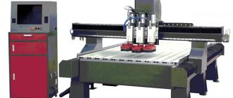
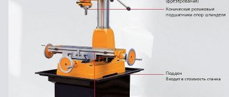
Hand-held wood-cutting tools include various saws, axes, chisels, chisels, knives (pieces of iron) for sherhebels, planes and hand jointers. The machine-made wood-cutting tool (Fig. 2) is complex in design: depending on the type of mechanical processing of wood, the following is used:
- in circular saws - circular saws (a);
- in planing – planing knives (b);
- in milling - shaped cutters (c), end cutters (d);
- in drilling machines - drills (e, f), countersinks (g), chisels (h), etc.
Based on the material from which the blades are made, the tool is divided into the following types:
- steel cutting tool;
- high-speed cutting tool;
- carbide cutting tools;
- mineral ceramic cutting tool;
- diamond tool, its blades are made of synthetic diamonds or polycrystals of cubic boron nitride.
Rice. 2. Wood-cutting machine tools: a – circular saw; b – planing knife; c – shaped cutter; d – end mill; d, f – drills; g – countersink; h – bit
For the purpose of uniform preparation of technical documentation in production, mechanical engineering standards have established a decimal system of classification and digital designations of tools and devices.
A unified system for designating technological equipment is used in technical documentation, when marking products, filling out applications, accounting and storing products.
Requirements for the material
The material of the cutting tool must provide such a combination of properties that the tool works equally well both in the initial running-in stage of wear and in the subsequent stage of monotonic wear. The following requirements apply to the material:
- strength , which reduces running-in wear and ensures performance when cutting thick layers of wood;
- high fatigue strength providing the ability to resist cyclically changing contact loads;
- plasticity , necessary for performing a number of operations to prepare the tool, for example, setting, flattening saw teeth, etc.;
- hardness , which determines the resistance of the metal to abrasion;
- heat resistance , ensuring that mechanical properties remain unchanged when heated;
- resistance against corrosion , creating the ability to process raw wood when the blade is subject to electrochemical corrosion.
Thus, the material of the wood-cutting tool must be durable, ductile, hard, heat-resistant, and resistant to corrosion. These properties are possessed by tool steels (high-quality, high-quality, alloyed, high-speed) and hard alloys (cast, tungsten-cobalt, synthetic superhard materials based on boron nitride, polycrystalline diamond alloys).
Compared to alloy steels, hard alloys can increase the service life of the tool. Cast hard alloys increase the service life by 3...7 times, tungsten-cobalt - by 20...50 times, mineral-ceramic plates - by 200...250 times, PKA - by 300...1000 times.
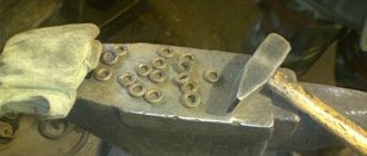
Replaceable cutting inserts
In recent years, rotary cutting inserts, which have 2...4 cutting edges, have been widely used in milling heads. After one cutting edge has become dull, the plate is rotated and the tool works with the other sharp cutting edge. They are made of hard alloy for one-time use. After all cutting edges have become dull, the plates are not sharpened, but replaced with new ones. The cutting inserts are mechanically secured to the milling heads. To do this, they have mounting holes with which the plates are based on pins.
In Fig. Figure 3 shows examples of rotary cutting inserts. The profiles of the cutting edges of the inserts can be varied. Profile plates can be rotatable.
Rice. 3. Cutting plates: a – rotary; b - profile
Brief information about metal powders
Metal powders are small crystalline grains (fractions) ranging in size from 10 to 500 microns, sometimes up to 1 mm.
The grains can be needle-shaped, spherical, hollow spherical, lamellar or scaly in shape. The physicochemical and technological properties of metal powders are determined by their chemical composition, pycnometric density, structure, mass fraction of impurities, gases, metal and other contaminants of the powders. Metal powders are the basis for the production of carbide materials. They are produced both from pure metals (chrome, nickel, cobalt, molybdenum, vanadium, etc.) and from metal carbides (tungsten, titanium, tantalum carbides). The industry that produces powders (hard alloy materials) is called powder metallurgy. The following methods for producing carbide materials are used in powder metallurgy:
- physico-chemical;
- thermometallurgical;
- mechanical;
- combined.
Powder metallurgy includes two independent branches of production. The first is the production of various powdery materials (powders, grains, granules, electrodes, monoliths and semi-finished products). The second is the processing of powdered materials into products (turning and milling inserts, blanks for monolithic tools, attachments for drilling and cutting tools, dies, electrode materials, monoliths, electrical contacts and various structural products).
Currently, powder metallurgy has established the production of various products from carbide materials, including high-purity filters, friction and anti-friction parts, plates for surfacing cutting, impact, drilling, abrasive and other tools.
High-alloy structural and tool steels are produced on the basis of powder metallurgy, for example, steel grade X23N18. Products from this steel are made by sintering powders. Steel is used for the manufacture of sliding bearings (liners). After chemical-thermal treatment (sulfiding or boriding) of these liners, scuffing and adhesion are eliminated and softness of shaft sliding is created. Such a pair can operate at elevated temperatures (up to 600 °C) and in aggressive environments.
For the manufacture of sealing parts (rings, gaskets, liners), steels based on the chromium-nickel-graphite system, obtained from metal powders, are used. These parts are used in gas turbines and apparatus. They withstand exposure to active gas environments, high temperatures and pressures.
Alloys made from powders based on chromium, nickel and titanium (X65N32, X66N30T4, X68N20T2, etc.) are used for the production of electrodes (welding structures made of high-alloy steels operating in aggressive environments and at high temperatures). High-alloy powders are also used to produce tool high-speed steels (R6M5F3, R6M5K5, R12MF5, R12M3F2K8, etc.), which are used for the manufacture of solid cutting tools for processing parts and workpieces made of high-strength and heat-resistant, including corrosion-resistant steels and alloys. Practice shows that the cutting properties of tools made from these steels are significantly higher than those from steels obtained by melting and subsequent rolling. They withstand high cutting conditions at elevated temperatures, their red hardness is more than 600 °C. For example, a tool made of steel grade R6M5K5 at an operating temperature of 650 °C will have a hardness of 52 HRA. If the tool life of a tool made of steel R6M5K5, made by casting and rolling, at a temperature of 650 °C and a hardness of 52 HRA is 240 minutes, then a tool of the same brand, made from powders, under the same cutting conditions will have a tool life significantly higher (approximately 360 ... 420 minutes ).
Powder metallurgy has also mastered the production of tungsten-free high-speed steels (Р0М6Ф1, Р0М2Ф3, Р0М10Ф3, etc.). These steels are much cheaper because they do not contain expensive tungsten. They have a dense, fine-grained and stable structure. Tools made from these steels have higher durability and red resistance.
Woodworking machines
Machine types
Taking into account social needs and the scientific and technical level, woodworking equipment can perform four functions: technological, energy, management and planning.
If a technical device performs a technological function, then it is called a working machine.
A working machine is a mechanism or a combination of several mechanisms that perform certain appropriate movements to perform useful work. In the simplest case, all movements of the working machine are performed manually. For example, a gate for lifting water from a well, a drill for drilling holes, a meat grinder allow you to perform useful work and are manually driven.
Working machines that change the shape and dimensions of the workpiece by cutting are called machine tools.
Working machines that perform work using pressure are called presses.
Machines that perform work operations without changing the shape, size and quality of the object of labor are simply called machines (sorting, packaging, transporting, etc.).
Machines that carry out physical and chemical effects on the object being processed are called devices.
In order to facilitate the work of workers, increase productivity and improve the quality of products, a person transfers partially or completely other functions to the working machine: energy, management, planning.
If an energy function is transferred to the working machine (drive of the main movements, feed, etc.), then the machine becomes mechanized. Mechanization only reduces or partially relieves a person from heavy manual labor, since the control function (turning on, turning off, regulating the mode, loading and removing workpieces, etc.) still remains with the person.
If energy and control functions are transferred to a working machine, then it turns into an automaton and completely eliminates direct human participation in the work.
The machine independently performs all the working and idle strokes of the cycle according to a program previously compiled and debugged by a person. In this case, the working machine no longer replaces only muscles, but also, to a certain extent, the human brain. The person only has the function of monitoring, adjusting, preparing and replacing programs.
If the working machine is also given the planning function (selecting the desired program using a work planning system), then only the function of drawing up programs remains with the person.
If the energy and control functions are not completely transferred to the machine, then the working machine is called a semi-automatic machine. Typically, on semi-automatic machines, a worker manually installs, secures and unfastens the workpiece, and turns on the machine feed.
Lines
To perform technological operations, working machines are installed in lines, which can be in-line, automatic or semi-automatic.
A production line is a line of working machines located in the order of the sequence of operations of the technological process and requiring individual maintenance. The machines included in the production line may or may not be connected by vehicles. In a sawmill, for example, there are one or more production lines. The line machines are installed in a strict sequence of technological operations, and each machine is serviced by one or more workers. In this case, the machines are connected to each other by conveyors.
An automatic line is a system of machines located in a technological sequence, united by means of transportation and control, which automatically performs a set of operations and only needs monitoring and adjustment. Loading of the head machine of the line and removal of finished products is carried out by loading and unloading devices.
If some line operations are performed with the participation of a worker, then such a line is called semi-automatic.
Machine diagrams
Schemes are design documents on which the component parts of the product, their relative positions and connections are graphically depicted using conventional symbols. The diagram allows you to quickly understand the design and sequence of actions of the device elements.
The types, types and general requirements for the implementation of circuits are established by GOST 701-84. To design and study the designs of woodworking equipment, the following schemes are used: technological (functional), kinematic, hydraulic, pneumatic, electrical. The diagrams are not drawn to scale. The spatial arrangement of parts of the product can be ignored.
Technological (basic) diagram
A technological diagram is a machine diagram that reflects the principle of its operation and the nature of the movements of its working parts and the workpiece.
The technological diagram shows what movements of the working bodies must be made to ensure normal safe operation of the machine. It shows the conventional outline of the workpiece and the tool, the basing, guiding, pressing and feeding elements, their relative position and direction of movement. In Fig. 4 shows a technological diagram of a circular saw for longitudinal sawing of lumber.
The diagram shows saw 1, lower feed rollers 2 and 6, upper feed rollers 3 and 4, upper and lower claw curtains 5, which prevent the workpiece 8 from being thrown back, and a side guide ruler 7. The workpiece interacts with all of the specified elements of the machine. In this case, each working body performs its specific function. The arrows show the direction of movement of the workpiece and the working parts of the machine. The diagram also indicates the maximum and minimum dimensions of the workpiece being processed.
Rice. 4. Technological diagram of the TsA-2A machine
Kinematic diagram
Each machine consists of kinematic elements (links) - shafts, gears, pulleys, sprockets, etc. The links interacting with each other form kinematic pairs. From kinematic pairs, kinematic chains are formed that connect the motor mechanisms of the machine with the executive ones.
The kinematic diagram of the machine reflects the method of transmitting movements in the machine from the motor mechanisms to the actuators.
Symbols for elements of kinematic diagrams are carried out in accordance with GOST 770-68. The implementation rules are set out in GOST 703-75.
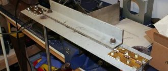
In Fig. Figure 5 shows a kinematic diagram of the main movement mechanism of the circular saw.
The movement from the electric motor 1 is transmitted to the saw through a V-belt drive, including pulleys 2 and 3. The kinematic diagram can be read as follows: movement from shaft I of the electric motor is transmitted to saw shaft II by a belt drive.
The kinematic diagram allows you to calculate the speeds of the working movements of the machine or select kinematic pairs according to the given speeds of the working movements. To do this, the diagram shows the designation and characteristics of all its elements.
Rice. 9..5 Kinematic diagram of the main movement mechanism of a circular saw
Innovative technologies in the production of hard alloys
Currently, enterprises producing hard alloys are introducing progressive technologies that make it possible to supply hard alloy inserts to the market, including the international market, to equip various cutting tools with them. For example, at the Kirovgrad Hard Alloy Plant OJSC (Sverdlovsk region), together with the Institute of Solid State Chemistry of the Ural Branch of the Russian Academy of Sciences and other research institutes of the Russian Federation, a set of measures has been developed, the implementation of which makes it possible to produce hard alloy plates that are not inferior in quality to the products of Western companies. Nanostructured hard alloys are being developed to replace conventional fine-grained hard alloys used in the production of metal-cutting, drilling, stamping, end and other tools. Import-replacement metal-cutting inserts, which are in great demand among machine-building enterprises, are also being introduced into production.
Technologies have been introduced and new equipment has been mastered, such as spray drying of carbide mixtures, vacuum-compression sintering furnaces, an attritor for preparing mixtures, a press with robotic removal of parts, installations for coating, a fleet of ultra-precision grinding equipment, etc. All this in a single complex is aimed at production of high-tech products - replaceable multifaceted inserts with a high degree of accuracy, with new geometry of the front surface, new chipbreakers and wear-resistant coatings, high volumetric porosity (0.02% instead of 0.2%).
Recently, the Kirovograd Hard Alloy Plant OJSC has mastered the production of 44 types of high-precision replaceable multifaceted inserts. The consumers of these plates are about 40 machine-building, metalworking and tool enterprises, such as OJSC NPK Uralvagon, OJSC Tomsk Instrumental, etc. Reviews about the quality and reliability of metal-cutting tools, their performance properties coming from consumer enterprises are positive. In addition, the plant entered the international market with its products. Let's take a brief look at some of the innovative technological processes being implemented at KZTS OJSC.
- Development of nanostructured hard alloys. Thanks to the introduction of this technology, the problem of further economical use of expensive tungsten, titanium-tungsten and titanium-tungsten hard alloys has been solved; on their basis, the production of new materials with higher properties has been mastered.
- Production of carbide rods for monolithic tools (mills, drills, taps, etc.). For these purposes, a new submicron alloy has been created, which has been assigned the grade A04 and its modification A04-6 (Table 8.1). These alloys are created by modifying the carbide mixture by adding tungsten carbide nanopowder (60 nm). This alloy in its physical, mechanical and operational properties is not inferior to analogues produced by world leaders in the production of hard alloys.
- The use of vacuum-compression sintering furnaces makes it possible to obtain a virtually pore-free alloy. This is achieved by compressing the products during the sintering process with argon pressure of 50 bar. A decrease in volumetric porosity from 0.2% to 0.02% results in an increase in physical and mechanical properties and operational durability by 10 ... 20%.
- The introduction of mixture drying units by spraying HC120 (NIRO A/S, Denmark) made it possible to obtain a better granulometric composition of the carbide mixture fractions. At the same time, hard, dangerous and unproductive labor of workers was eliminated, which led to a sharp increase in labor productivity and the preservation of people's health.
| Table 1. Properties of innovative submicron alloys A04 and A04G6 | |||||
| Alloy grade | Hardness HRA, not less | Density, g/cm2 | Bending strength, kgf/mm2 (N/mm2), not less | Coercive force, no less | |
| kA/m | Oersted | ||||
| A04 | 92,0 | 14,35 … 14,6 | 270 (2 646) | 23,9 | 300 |
| A04-6 | 93,0 | 14,7 … 15,0 | 150 (1470) | 25,6 | 320 |
High performance properties of cutting tool inserts are achieved through a combination of design, grade of carbide, application method and type of wear-resistant coating. Modern wear-resistant coatings used to cover imported replacement plates, which have been tested at machine-building plants, have shown high quality.
The highest performance qualities are achieved by coatings created using technology for applying wear-resistant mono- and multi-coatings to plates and end tools:
- by chemical vapor deposition (CVD);
- using ion plasma coating (PVD) method. Mono- and multi-coatings of inserts and end tools are made on the basis of the following materials: TiN, TiCN, TiAlN, AlTN, TiAlSiN, Al2O3, etc. These coating materials are used in various combinations.
For the chemical vapor deposition (CVD) method, a BERNEX BPXpro 530 LT unit (Germany) is used. This method is used to coat turning inserts. The CVD method produces coatings of several types:
- CVD coating type RT - golden color, four-layer (two layers of titanium nitride and one layer each of titanium carbonide and aluminum oxide), wear-resistant. The titanium carbonide layer ensures strong adhesion of the coating to the carbide plate, maintaining viscosity and adhesion at high temperatures. Titanium carbonide imparts toughness to the cutting edge and resistance to peeling and chipping. Aluminum oxide has high hardness, low adhesion and high heat resistance. This coating can withstand dynamic loads, impacts and is used for processing castings and forgings;
- CVD coating type RT-R - black and gold color. The front surface of the SMP is coated with aluminum oxide, has a black color, a polished surface, which facilitates easy chip flow and removal of heat from the cutting zone. The back surface is yellow in color and coated with a wear-resistant layer of titanium nitride. The appearance of black marks on the back surface during operation indicates wear of the cutting edge.
Other types of CVD coatings are also used.
A cutting tool equipped with CVD-coated inserts, depending on the type and composition of the coating material, has the following properties:
- thickness of coating layers - from 0.1 to 3.9 microns;
- maximum temperature of use (red resistance) - 720 ... 1,050 ° C;
- microhardness - 2,600 ... 3,000 HV;
- friction coefficient - 0.15...0.32.
The PVD ion plasma deposition method produces two types of coatings: TT and AM. The TT type coating is golden-colored, three-layer (two layers of titanium nitride (TiN) and one layer of a complex TiAlN compound). Used for coating milling inserts and end tools. Depending on the composition of the material, these coatings have the following properties:
- thickness of coating layers - from 0.1 to 3.9 microns;
- maximum temperature of use (red resistance) - 600 ... 1,200 ° C;
- nanohardness - 24 ... 45 GPa;
- friction coefficient - 0.5 ... 0.7;
- high adhesion, Rockwell hardness and scratch test (N).
The AM type coating is dark purple in color and consists of numerous multilayers of AlTiNi and TiAlNi compounds. Such multilayer coatings are used for tools used for intermittent cutting of metals, unstable conditions and high mechanical loads. Designed for milling tools when processing castings, forgings and stampings (carbon, alloyed, corrosion-resistant and other steels).
When tested at JSC NPK Uralvagonzavod, cutting tools manufactured on the basis of new technologies showed durability 1.8 times higher than the basic durability of conventional carbide tools. Tests of cutting tools equipped with inserts with a new geometry of the front surface and new chipbreakers, carried out at JSC NPO ISKRA, showed the high durability of such inserts, namely 578 minutes, which significantly exceeds the level of durability of inserts produced by Western companies. It should be noted that the maximum durability of turning cutters equipped with carbide inserts of types VK, TK or TTK is 120 minutes. Positive results were obtained when testing inserts for roughing on machines at Belebeevsky. The durability of the plates is increased by 60%. The durability of tangential plates when processing carriage wheels at JSC NPK Uralvagonzavod increased by 20%.
Innovative technologies, chemical composition of plates and coatings introduced by hard alloy plants are radically changing traditional ideas about hard alloys. In this regard, new designations of plates made of hard alloys are used, namely: A05 (VK3-M), A10 (VK60-M), A20 (VP322), A30 (VK10-OM), B20 (MS321), B25 (VK6) , V35 (VK8), N05 (T30K4), N10 (T15K6), N20 (T14K8), N30 (T5K10), T20 (MS221), T25 (MS137), T30 (TS125), T40 (MS146), T50 (TT7K8) . (The old designations of analogues of hard alloy grades are given in parentheses.)
The alphanumeric designation adopted for the marking of new alloys is:
1st character (letter) - alloy group: N-TK-alloys; T-TTK, M, TSalloys; V-VK-alloys; A-fine-grained VK alloy;
2nd character (letter) - coating method: C - chemical vapor deposition (CVD); P — ion-plasma coating (PVD);
3rd and 4th digits - main ISO application group (P, M, K, N, S, H) and numerical index: 01, 05, 10, 15, 20, 25, 30, 35, 40, 45 , 50;
5th character - type of coating (letter): A, B, E, K, N, O, P, T - indicate a different combination of chemical elements covering the hard alloy;
6th character - type of processing: T (Tuminq) - turning; M (Milling) - milling.
For example, the new generation hard alloy VS35RT (analogue of alloy VK8) has the following designation: B - group of alloy VK; C - coating method - chemical vapor deposition (CVD); 35 - numerical index of the application group; P - type of coating; T—type of processing. Thus, we conclude that a replaceable multifaceted insert made of hard alloy grade VK8, obtained by vacuum-compression sintering, having undergone additional coating treatment in a gas environment, is used for soldering to turning tools (for turning materials with the formation of drain chips).
Another example. The new generation hard alloy NS10NM (analogous to the T15K6 alloy) has the following designation: N - TK alloy group; C - coating method - chemical vapor deposition (CVD); 10 - numerical index of the application group; N - type of coating; M - processing method (Milling - milling), i.e. a replaceable multifaceted insert made by vacuum-compression sintering, having received a coating in a gaseous environment, is used for attachment to a milling tool (for milling austenitic and free-cut steels, alloy and malleable cast iron, during the processing of which elemental chips are formed).
As practice shows, cutting tools equipped with carbide inserts made on the basis of innovative technology have higher mechanical and performance properties and successfully compete in the market with tools supplied by Western companies.