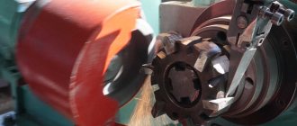
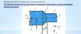
The essence of the process
Milling is a procedure carried out on special machine equipment. During it, a layer (surface or deep, internal part) is removed from the workpiece. During it, various materials can be used, the most popular of which are wood or metal, so we are mostly talking about metalworking.
How the process works. The workpiece is fixed on the bed. Select a suitable cutter or abrasive material, such as a grinding wheel. The equipment produces rotational movements around its axis, as well as movements along two planes. At the same time, longitudinal advancement of the workpiece towards the cutter is possible.
The difference from a lathe is that a milling machine involves rotating the part, that is, circular processing. And in this case, you can grind products of almost any shape, including grinding a smooth surface, making grooves and other holes, including shaped ones. Metalworking can be of two types - rough and finishing. Of course, there are many more stages, but, as a rule, 2 or 3 passes are made. This allows you to create the desired surface profile, such as grooves or teeth.
The movement of the working tool is intermittent. An interesting feature that distinguishes milling from drilling or turning is the position of each tooth during the machining process. They work, come into contact with the surface one at a time, and not all together. This increases the load on each of the edges of the cutter. And only optimization of cutting conditions during milling will help minimize the impact.
Selecting a mode depending on the material
All materials are characterized by certain performance characteristics, which must also be taken into account. An example is bronze milling, which is carried out at cutting speeds from 90 to 150 m/min. Depending on this value, the feed amount is selected. PSh15 steel and stainless steel products are processed using other parameters.
When considering the type of material being processed, attention is also paid to the following points:
- Hardness. The most important characteristic of materials is hardness. It can vary over a wide range. Too much hardness makes the part strong and wear-resistant, but at the same time the processing process becomes more complicated.
- Degrees of machinability. All materials are characterized by a certain degree of workability, which also depends on ductility and other indicators.
- Application of technology to improve properties.
A fairly common example is hardening. This technology involves heating the material followed by cooling, after which the hardness index increases significantly. Forging, tempering and other procedures for changing the chemical composition of the surface layer are also often carried out.
In conclusion, we note that today you can find simply a huge number of different technological maps, which you just need to download and use to obtain the required parts. When considering them, attention is paid to the type of workpiece material, type of tool, and recommended equipment. It is quite difficult to independently develop cutting modes; in this case, you need to do a preliminary check of the selected parameters. Otherwise, both the tool and the equipment used may be damaged.
Basic concepts about the operation of milling machines
Equipment can be completely different; the main classification depends on the plane in which the working area is located. In this regard, a distinction is made between vertical and more common horizontal frames. Accordingly, the location of the spindle and fasteners will be different. According to their specifications, there are universal (multifunctional) machines, as well as specialized ones, for example:
- to form smooth planes;
- for cutting figured grooves;
- gear cutting equipment (creating gear connections) and so on.
These were listed examples when working on metal. And for wood - manual, stationary, spindle and drum (they are very dangerous, so they are rarely used now, but they are very effective).
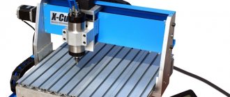
Separately, it is worth mentioning those machines that are equipped with a numerical control panel (CNC). They have the following advantages:
- Ease of operation: the operator does not need to make many movements, you can only observe and control the actions.
- The program independently calculates the optimal motion pattern and cutting mode during milling. This will be the shortest route for moving the cutter with maximum efficiency.
- Increased cutting accuracy. Here are the minimum permissible errors, which cannot be compared with those that occur during mechanical, manual processing.
Returning to simpler machines, let's see what main components it has:
- Bed. It is strong and should withstand almost any load. It includes a built-in gearbox. This block is designed to regulate the rotation of a vertically standing spindle, as well as the cutter that is mounted on it.
- Table with cross runners. Workpieces that are subject to longitudinal movement are attached to it. Also at the bottom there is an object responsible for feeding. It includes different handles to determine movements.
Versatility increases if a rotary table is present - there are more functions that can be performed on milling equipment. In addition, the highly versatile devices additionally have two spindles, which makes it possible to implement various milling technologies.
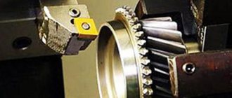
Classification of cutters
Mills are devices for cutting. The main physical parameters by which they are assessed: height, diameter, chamfer and relief values, circumferential pitch. There is a huge variety of them, distributed according to various characteristics:
- by type of surfaces being processed (for wood, plastic, steel, non-ferrous metals, etc.);
- in the direction of rotation - right-handed and left-handed;
- depending on the design features - solid, brazed, folding (have insert knives), welded;
- shape: conical, cylindrical, disk;
- Depending on the working conditions and requirements for the cutting part, they can be made of various materials. These include: carbon tool and high-speed steel (alloyed, with a high tungsten content), hard alloy (strong - for roughing, wear-resistant - for finishing). Common options are when the body is made of carbon or high-speed steel, and the knives are inserted carbide;
- depending on the purpose: cylindrical, end, end, slotted, cut-off, shaped.
The most informative features: cutting edge material and purpose.
The classification of cutters depends on the purpose of cutting modes during milling
There are more than 1000 different types of cutters, which can be divided according to numerous parameters and sizes. Its choice directly depends on the rules of movement (rotation speed, direction, presence of counter feed and its power) of the tool. They are also directly determined by the type of metalworking - roughing or finishing. So, let's look at what classifications are carried out:
- according to the workpiece material - there are separate cutters for metal (different for different alloys), wood, plastic and other synthetic substances;
- in the direction of rotation - right-handed and left-handed, by the way, the ease of chip removal depends on this;
- according to design features - alloy, monolithic, folding with the ability to replace cutting parts, etc.;
- in shape - there is a wide variety here, so listing them all is almost pointless, note that there are round, cylindrical, conical disk;
- according to the material of manufacture - it can be tool or high-speed steel, carbide metal, carbon or other alloys;
- by purpose - the largest division, which should include end, end, cutting, shaped, and so on.
When choosing the recommended cutting mode, you should especially pay attention to what material the cutting edge is made of, as well as what the cutter is intended for.
Formulas for different types of cutters
Formulas for straight edge cutters
Formulas for cutters with round inserts
Ball end cutters
Up and down milling
As we noted above, there are two feeds - movement and movement of the workpiece. Accordingly, in relation to each other they can be:
- Co-directional. This results in an increased load on the teeth, and accordingly, their wear accelerates. In this case, the power is reduced by an average of 10% of the second type of movement. This is the optimal solution for the finishing stage of metalworking.
- Multidirectional, that is, both feeds (workpieces) are arranged towards each other. The teeth of the equipment gradually, one by one, cut into the material; it is believed that in this case the mechanical force on each cutting edge is distributed gradually and in proportion to the speed. But this technology is not suitable for the finishing stage of work, because hardening may form during it. This is done at the moment of contact of the cutter with the surface due to the opposite direction. This phenomenon will not only make the cut unsightly, but will also increase the wear rate of the working tool. Therefore, this method is mainly used for primary (roughing) or rough processing.
Definitions for cutters
Principal plan angle (kr), degrees.
The leading angle (kr) is the main geometric parameter of the cutter, as it determines the direction of the cutting force and the thickness of the chip.
Cutter diameter (Dc), mm
The diameter of the cutter (Dc) is measured through the point (PK) where the main cutting edge intersects the parallel chamfer.
The most informative parameter is (Dcap) - the effective cutting diameter at the current cutting depth (ap), it is used to calculate the cutting speed. D3 is the maximum diameter of the inserts; for some types of cutters it is equal to Dc.
Depth of cut (ap), mm
Depth of cut (ap) is the distance between the machined and uncut surfaces, measured along the axis of the cutter. The maximum ap value is limited mainly by the insert size and machine power.
When performing rough operations, the amount of transmitted torque is essential. At the finishing stages of processing, the presence or absence of vibrations becomes more important.
Milling width (ae), mm
The milling width (ae) is the amount of allowance to be cut, measured in the radial direction. This parameter is especially important when plunger milling. The maximum value of ae also plays a significant role in the occurrence of vibration in corner milling operations.
Overlapping width (ae/Dc)
The overlap width (ae/Dc) is the ratio of the milling width to the cutter diameter.
Effective number of cutter teeth (zc)
This value is used to determine the minute feed (vf) and productivity. This often has a decisive impact on chip evacuation and machining stability.
Number of cutter teeth (zn)
The value is selected taking into account compliance with the condition of uniformity of the milling process. It is the number of passes that determines the type of milling, the group of materials to be processed and its rigidity.
Cutter tooth pitch (u)
For a certain cutter diameter, you can choose different tooth pitches: coarse (L), normal (M), fine (H). The letter X in the cutter code indicates a particularly fine tooth pitch
Basic concepts about cutting modes, milling on CNC machines
This is more advanced equipment that has a numerical control unit. That is, an embedded computing device (computer) with software. It, that is, the software, is aimed at determining the appropriate processing speed, selecting the desired direction of rotation, as well as the trajectory of the cutter. The main task of CNC installation is process automation. Therefore, the operator only observes during milling. This significantly reduces the number of defects, because there is no human factor, which often leads to errors.
In addition to the accuracy of the workflow and automatic mode selection, it is also worth noting increased productivity. Simply put, it will not replace the work of three, or even more mechanical, hand-held devices. And this despite the fact that the work of a milling machine operator is much harder, and the possibility of defects or injury is higher.
Most often, end or end ones are used on CNC. They are quite versatile and have a wide range of purposes. But there are many standard sizes, the required subtype can be selected according to a number of parameters, these are:
- the type of chips that are formed;
- software parameters;
- strength of the processed material, etc.
Milling cutters of this category differ in the number of passes (the most popular are double-pass), which leads to chip removal and the presence of sharp edges. If the material is soft (for example, wood), and the chips are long and wide, then it is typical to use a fast cutting mode when milling wood using a single-cut tool. Multi-pass, on the contrary, will be needed when hard metals are processed (then the chips come out not monolithic, but as if broken).
Table: cutting speed of materials
| Material | Speed (meters per minute) |
| Aluminum | from 200 to 400 |
| Brass | from 150 to 300 |
| Bronze | from 100 to 150 |
| Bakelite | from 50 to 100 |
| PVC | from 100 to 200 |
| Thermoplastics | from 300 to 500 |
| Various types of wood | from 300 to 500 |
| Stainless steel | from 50 to 90 |
The table contains general values for most machine tools, but they may go beyond the specified scope depending on the modification of the milling machines and the characteristics of the material. For example, plywood has a lower stiffness rating than wood, so standard speed values will not work.
Cutter rotation speed
The simplest formula looks like this:
n (rpm) = 1000 Vc (desired cutting speed) / π D (cutter diameter).
Recommendation
From a safety point of view, you should not drive the spindle at maximum speed. This means that only due to this, the cutting speed will decrease by approximately 10 - 15%. This “loss” can be partially compensated by installing a cutter with a larger diameter. This increases the speed slightly. If you don’t have a suitable one at hand, you will have to decide whether to spend money on a new tool or be content with the capabilities that the milling machine has. Again, all this can only be verified by practice working on specific equipment, but the general meaning of the recommendation is clear.
Useful tips
- Exceeding the optimal feed value is fraught with an increase in temperature in the working area, the formation of thick chips and rapid breakage of the cutter. For tools with a diameter over 3 mm, you should start with 0.15, no more
- If the speed of milling a part cannot be increased through optimal use of the equipment’s capabilities, you can try installing a two-flute cutter.
- When choosing a tool, you need to take into account that increasing the length of the cutting part leads to a decrease in feed and an increase in vibrations.
- You should not strive to increase the processing speed by replacing the cutter with a similar one, but with more teeth. The chips from such a tool are less well removed, and therefore often lead to a sharp decrease in the quality of milling. In some cases, when the grooves are completely clogged, the cutter begins to run idle. There is no sense in such a replacement.
Speed
Moving directly to the parameters, it is worth noting that this one is the most important. It characterizes the period of time over which a certain layer will be removed from the surface. Some milling operators who do not have a wide range of tasks are accustomed to single-speed mode. Others, correctly, change it depending on the material:
- Stainless steel has a very low machinability rate. This is due to alloying additives in the steel. Therefore, you should not exceed the interval from 45 to 95 meters per minute.
- Bronze is much softer, so it can cut up to 150 m/min.
- Brass allows you to work in large ranges - from 130 to 320 meters per minute. However, be careful - with a significant increase in heating, the material becomes very plastic, which can lead to deformation.
- There are several aluminum alloys; when calculating cutting conditions for a milling operation, it is necessary to determine the specific composition of aluminum. That’s why the boundaries are so wide – from 200 to 420 m/min.
When setting, the number of rotation revolutions per unit of time is set; they can be calculated using the formula:
n=1000 V/D, where:
- V is the recommended processing speed (see it in the table below);
- D is the diameter of the cutter, it can be recognized by the corresponding markings on the tool.
Experienced milling operators give a recommendation: do not drive the spindle at high speeds, because with such intensive work the machine wears out very quickly. It is better to calculate the cutting mode when milling according to the specified formula and remove another 10-15 percent from the obtained result. How fast the tool rotates depends on:
- Processing quality. For example, the peeling will be characterized by significantly lower speeds than the finishing.
- Productivity, the number of parts/tasks completed in a period of time.
- Tool wear increases in proportion to the frictional force that occurs when the cutting edge comes into contact with the surface.
Selecting a mode depending on the type of cutter
To obtain the same product, a variety of types of cutters can be used. The choice of basic milling modes is carried out depending on the design and other features of the product. Cutting modes when milling with disk cutters or other design options are selected depending on the following points:
- The rigidity of the system used. An example is the features of the machine and various equipment. The new equipment is characterized by increased rigidity, which makes it possible to use higher processing parameters. On older machines, the rigidity of the system used is reduced.
- Attention is also paid to the cooling process. Quite a large amount of equipment provides for the supply of coolant to the processing zone. Due to this substance, the temperature of the cutting edge is significantly reduced. Coolant must be supplied to the material removal zone continuously. At the same time, the resulting chips are also removed, which significantly improves cutting quality.
- Processing strategy also matters. An example is that the production of the same surface can be carried out by alternating various technological operations.
- The height of the layer that can be removed in one pass of the tool. The limitation may depend on the size of the tool and many other geometric features.
- Size of processed workpieces. Large workpieces require a tool with wear-resistant properties that will not heat up under certain cutting conditions.
Taking into account all these parameters allows you to select the most suitable milling parameters. This takes into account the distribution of allowance when milling with spherical cutters, as well as the features of processing with an end mill.
The classification of the instrument in question is carried out according to a fairly large number of characteristics. The main thing is the type of material used in the manufacture of the cutting edge. For example, the VK8 cutter is designed to work with workpieces made of hard alloys and hardened steel. It is recommended to use this design option at low cutting speeds and sufficient feed. At the same time, high-speed cutters can be used for processing with a high cutting rate.
As a rule, the choice is made taking into account common tables. The main properties are:
- Cutting speed.
- Type of material being processed.
- Type of cutter.
- Speed.
- Innings.
- Type of work performed.
- Recommended feed per tooth depending on the cutter diameter.
The use of regulatory documentation allows you to select the most suitable modes. As previously noted, only a specialist should develop the technological process. Mistakes made can lead to tool breakage, a decrease in the quality of the workpiece surface and errors in the tools, and in some cases, equipment breakdown. That is why you need to pay a lot of attention to choosing the most suitable cutting mode.
Depth
This is what layer the cutter enters the material. Peculiarities:
- Dependence on density and other characteristics of the workpiece.
- During rough metalworking, the cut-in is large, but during finishing and finishing, a minimal layer is removed.
- The natural limitation is the size of the cutting edge.
A correctly selected parameter determines:
- procedure performance, processing speed;
- appearance and quality of the resulting surface.
It's not always fast - it's as deep as possible at one time. In many cases, it will be more productive to make 2-3 passes to a smaller depth. This will improve the cut and also maintain the integrity of the cutter for a longer period.
Depth of cut
The other most important parameter is the milling depth. It is characterized by the following features:
- The cutting depth is selected depending on the material of the workpiece.
- When choosing, attention is paid to whether roughing or finishing is carried out. When roughing, a larger plunge depth is selected, since a lower speed is set. During finishing, a small layer of metal is removed by setting the tool to a high rotation speed.
- The indicator is also limited by the design features of the tool. This is due to the fact that the cutting part can have different sizes.
The depth of cut largely determines the performance of the equipment. In addition, such an indicator in some cases is selected depending on what kind of surface needs to be obtained.
The power of the cutting force during milling depends on the type of cutter used and the type of equipment. In addition, rough milling of a flat surface is carried out in several passes when it is necessary to remove a large layer of material.
A special technological process can be called the work of obtaining grooves. This is due to the fact that their depth can be quite large, and the formation of such technological recesses is carried out exclusively after finishing the surface. Milling T-slots is carried out using a special tool.
Innings
Another very important parameter that greatly determines the life of the cutter. Here's what depends on the selected mode:
- Thickness of the cut layer.
- Machine performance.
- Level of accuracy.
When choosing, very often milling cutters primarily pay attention to the recommendations of cutting tool manufacturers. Usually the following relationship works: the higher the feed, the lower the cutting speed. This is due to an increase in axial load. If you select a high level for both parameters at the same time, you may experience increased wear. Most often, the indicator is selected in the range of 0.1-0.25.
Processing stages
The parts are made from rods having different sections and shapes: square, hexagonal, round and others. If it is necessary to remove a layer of material that exceeds the volume of the part itself, then they try to use blanks in the form of castings or forgings.
Processing of parts on machines is carried out in several stages:
- The first stage is rough grinding of the future part;
- A significant layer of material is removed;
- Next, the material should be finished.
An important point when processing parts: depending on how high precision is required to manufacture the part, roughing can be done on a very powerful and not the most accurate machine, but finishing roughing can be done on a precision machine, albeit less powerful.
Milling width
This parameter does not always need to be entered manually. Usually it directly depends on the diameter of the cutter. Thus, it can be adjusted simply by choosing the “right” tool. For example, for the corresponding groove width. Accordingly, the higher the value, the larger the layer that is cut off at a time. As a rule, the service life of the tool also decreases with long operating times.
But due to the large milling width, it is possible to make a groove in one pass instead of two or more.
Left-hand cutters
Why versus feed milling is better.
1. Dive:
The cutter must be able to penetrate the material with its end (drilling function).
2. Cutting edge:
As a rule, the edges of the passage differ from each other.
The opposite side of movement is “more beautiful” than the side of synchronicity. This is especially noticeable when using a 1-flute cutter, as well as when milling aluminum. Advice;
Mill the inner contours clockwise, the outer contours counterclockwise. Thus, the “bad” side ends up in the chips
3. Chip removal:
The chips must be discharged quickly so that the cutter cavities do not fill, causing the cutter to break. The deeper and faster the milling occurs, the more difficult it is to remove chips. Directions: Do not rout deeper than double or triple the cutter diameter. Go through deeper grooves in several passes. When milling polystyrene and other plastics, it makes sense to use cutters with polished grooves for better output.
4. Heat dissipation/lubrication:
The cutter should not become too hot: On the one hand, a tool with too high a temperature loses its properties, on the other hand - even more critical - plastic and aluminum chips can “stick” in the grooves, preventing the removal of chips and, as a result, lead to breakage of the cutter. When processing metals, it is imperative to recommend a lubricant. Note: Aluminum and non-ferrous metals can be milled with alcohol or special emulsions; when processing plexiglass, soapy water can be used.
5. Risk of breakage:
grows linearly with increasing feed and increasing immersion depth: Double feed means double fractional risk, double immersion depth means eight-fold fractional risk.
The right cut brings the chips to the top.
A right-hand cutter facilitates the removal of chips to the top, which is good for continuous removal; however, it has the disadvantage that the cutter, like a corkscrew, also moves the base material (workpiece) upward, “swirls” when milling wood or “buries” when processing thin sheet material ( for example tin). A cutter with a left helix on the contrary pushes down on the material and when routing fibrous materials such as wood or cardboard, you achieve a smoother top edge (the fibers are not lifted, but “pressed” into the base material). But here the negative factor is the difficulty of removing chips.
A. Right-hand cutting (normal form): Brings the chips to the top. The cutter has a tendency to "burrow" and lift up the base material. "corkscrew effect"
B. Left helix (special shape): Guides chips down when machining from the end, or used when working in an already milled cavity. The cutter presses down on the base material (the opposite of the “corkscrew effect”). Not suitable for deep milling.
How to choose from a table of cutting modes when milling CNC and manually: practical tips
Of course, you can and should use ready-made values, but you cannot ignore auxiliary factors, such as:
- milling machine experience;
- degree of cutter wear;
- the state in which the machine itself is located;
- technological capabilities of devices;
- cutter material;
- what the workpiece is made of;
- roughing or finishing process.
We will present tabular data that displays the main parameters depending on the actions:
| Type of work and material | Diameter, mm | Speed, rpm |
| Cutting/sampling acrylic, composite or PVC up to 10 mm | 3,175 | 18000 |
| Cutting/patterning wood or materials from wood components | From 3.175 to 8 | From 24000 to 15000 |
| Milling brass and bronze | 2 | 15000 |
| Duralumin cutter | 3,175 | 15000 – 20000 |
How to choose a mode in practice?
As previously noted, in most cases, technological maps are developed by a specialist and the master can only select the appropriate tool and set the specified parameters. In addition, the master must take into account the condition of the equipment, since limit values can lead to breakdowns. In the absence of a technological map, you have to select milling modes yourself. Calculation of cutting conditions during milling is carried out taking into account the following points:
- Type of equipment used. An example is the case of cutting when milling on CNC machines, when higher processing parameters can be selected due to the high technological capabilities of the device. On older machines that were put into operation several decades ago, lower parameters are selected. At the time of determining suitable parameters, attention is also paid to the technical condition of the equipment.
- The next selection criterion is the type of tool used. Various materials can be used in the manufacture of cutters. For example, a version made of high-quality high-speed steel is suitable for processing metal at high cutting speeds; a milling cutter with refractory tips is preferably selected when it is necessary to mill a hard alloy with a high feed rate during milling. The sharpening angle of the cutting edge, as well as the diametrical size, also matters. For example, as the diameter of the cutting tool increases, the feed rate and cutting speed decrease.
- The type of material being processed can be called one of the most important criteria by which the cutting mode is selected. All alloys are characterized by a certain hardness and degree of machinability. For example, when working with soft non-ferrous alloys, higher speed and feed rates can be selected; in the case of hardened steel or titanium, all parameters are reduced. An important point is that the cutter is selected not only taking into account cutting conditions, but also the type of material from which the workpiece is made.
- The cutting mode is selected depending on the task at hand. An example is rough cutting and finishing cutting. Black is characterized by a large feed and a low processing speed; for finishing, the opposite is true. To obtain grooves and other technological holes, the indicators are selected individually.
As practice shows, the depth of cut in most cases is divided into several passes during roughing, while during finishing there is only one. For various products, a table of modes can be used, which significantly simplifies the task. There are also special calculators that calculate the required values automatically based on the entered data.
Cutting speed
The most important mode during milling can be called cutting speed. It determines over what period of time a certain layer of material will be removed from the surface. Most machines have a constant cutting speed. When choosing a suitable indicator, the type of workpiece material is taken into account:
- When working with stainless steel, the cutting speed is 45-95 m/min. Due to the addition of various chemical elements to the composition, hardness and other indicators change, and the degree of workability decreases.
- Bronze is considered a softer composition, so this mode when milling can be selected in the range from 90-150 m/min. It is used in the manufacture of a wide variety of products.
- Brass has become quite widespread. It is used in the manufacture of locking elements and various valves. The softness of the alloy allows you to increase the cutting speed to 130-320 m/min. Brasses tend to increase in ductility when exposed to high heat.
- Aluminum alloys are very common today. In this case, there are several design options that have different performance characteristics. That is why the milling mode varies from 200 to 420 m/min. It is worth considering that aluminum is an alloy with a low melting point. That is why, at high processing speeds, there is a possibility of a significant increase in the plasticity index.
There are quite a large number of tables that are used to determine the main operating modes. The formula for determining cutting speed revolutions is as follows: n=1000 V/D, which takes into account the recommended cutting speed and the diameter of the cutter used. A similar formula allows you to determine the number of revolutions for all types of processed materials.
The milling mode in question is measured in meters per minute cutting parts. It is worth considering that experts do not recommend driving the spindle at maximum speed, as wear increases significantly and there is a possibility of damage to the tool. Therefore, the result obtained is reduced by approximately 10-15%. Taking this parameter into account, the most suitable tool is selected.
The rotation speed of the tool determines the following:
The quality of the resulting surface. For the final technological operation, the largest parameter is selected. Due to axial rotation with a large number of revolutions, the chips are too small. For roughing operations, on the contrary, low values are selected, the cutter rotates at a lower speed, and the chip size increases. Due to fast rotation, a low surface roughness is achieved. Modern installations and equipment make it possible to obtain a mirror-type surface. Labor productivity
When setting up production, attention is also paid to the performance of the equipment used. An example is the workshop of a machine-building plant, where mass production is being established.
A significant decrease in processing modes causes a decrease in productivity. The most optimal indicator significantly increases labor efficiency. The degree of wear of the installed tool. Do not forget that when the cutting edge rubs against the surface being processed, severe wear occurs. With severe wear, the accuracy of the product changes and labor efficiency decreases. As a rule, wear is associated with strong surface heating. That is why high-throughput production lines use equipment that can supply coolant to the material removal zone.
In this case, this parameter is selected taking into account other indicators, for example, feed depth. Therefore, the technological map is drawn up with the simultaneous selection of all parameters.
Main settings
One of the main tasks of technological preparation of production during turning operations is the determination of rational cutting conditions. When calculating them, the characteristics of the product being processed and the capabilities of the machine park, as well as the availability of appropriate tools, fixtures and equipment should be taken into account. The layout of the components and assemblies of a lathe allows for the implementation of two defining types of movement that form a given configuration of the surfaces of the part: rotation of the workpiece (main movement) and movement of the cutter deep into and along the surface of the part (feed). Therefore, the main technological parameters for turning equipment are:
- cutting depth;
- spindle feed and speed;
- cutting speed.
There is mutual influence of cutting modes and the main elements of the production economy. Among them, the most significant are:
- equipment performance;
- quality production indicators;
- cost of manufactured products;
- depreciation of equipment;
- tool durability;
- safety.
The concept of cutting modes
Turning at extreme conditions increases the productivity of turning equipment. However, such operation of machines is not always possible and advisable, because There are limitations in the form of the maximum power of the main drive, the rigidity and strength of the workpieces, as well as the technological parameters of the tool and equipment.
If the technological parameters are incorrectly calculated or selected, working at high speeds can cause increased vibration and imbalance of individual mechanisms of the lathe. This leads to a decrease in the accuracy and repeatability of product dimensions. In addition, the risk of tool breakage and machine failure increases.
Depth
Allowance is the thickness of metal removed by a turning tool from the workpiece before it reaches the final size. When turning and boring, it is removed in stages over a given number of cuts. The thickness of the metal removed per single cutter pass is called the depth of cut in machining and is measured in millimeters. In technological calculations and tables, this parameter is denoted by the letter t.
During turning operations, it is equal to 1/2 the difference in diameters before and after turning the part and is calculated by the formula:
t = (Dd)/2,
where t is the cutting depth; D—diameter of the workpiece; d – specified diameter of the part.
During trimming operations, this is the size of the metal layer removed from the end of the workpiece in a single pass of the cutter, and during grooving and cutting, this is the depth of the groove.
Depth of cut
Ideally, one pass of the cutter is required to remove the stock. But in reality, the turning process, as a rule, includes a roughing and finishing stage of processing (and for surfaces with high precision - even semi-finishing). If the characteristics and shape of the workpiece are good, both of these operations are performed in two or three passes.
Innings
Feed during turning is the length of the path during the transverse movement of the cutting edge of the cutter, which it makes per unit revolution of the spindle. It is measured in mm/rev, designated in technological documentation by the letter S and selected from technological reference books. The feed amount depends on the power of the main drive, the value of t, dimensions and physical properties of the workpiece being processed. When turning, it is calculated by the formula:
S=(0.05…0.25) ×t,
During the turning operation, the feed on the lathe should be set to the maximum possible number, but taking into account the technological parameters of the machine and the tool used. During rough turning operations, it depends on the power of the main drive and the stability of the part. And in finishing turning, the main criterion is the specified class of surface roughness.
Speed
The cutting speed during turning is the total trajectory of the cutting edge of the cutter per unit time. Its dimension is in m/min, and in tables and calculations it is designated by the letter v and is selected according to technological documentation or calculated using formulas. In the latter case, the calculation occurs in the following sequence:
- the t value is calculated;
- the value S is selected from the reference book;
- the table value vt is determined;
- the adjusted value vут is calculated (by multiplying by correction factors);
- taking into account the spindle rotation speed, the actual value vf is selected.
Cutting speed
This parameter is one of the main performance characteristics of metal-cutting equipment and directly affects the operating conditions of the lathe, tool wear and the quality of the machined surface.