Factors affecting machine performance
The choice of appropriate modes depends on a number of factors. For a CNC milling type machine, the most important factors are:
- spindle feed and rotation speed - the permissible rate is calculated depending on the capabilities of the cutting machine, the type of material being processed, as well as the complexity of the part;
- milling width - this indicator is adjusted based on the dimensions of the workpiece (exact data can be found in the drawing);
- milling depth - depends on the number of passes of the cutter (for simple milling on a machine, one pass is usually sufficient);
- cutting speed - the indicator is calculated based on the distance that the cutter travels on wood or other material within one minute (the speed is also set depending on the technical parameters of the workpiece);
- feed – an indicator of spindle movement along three axes;
- feed per minute - calculated to determine the time it will take the spindle to complete the task.
To set up modes and obtain the necessary information, it is recommended to use the instructions for the machine, as well as the permissible values and characteristics of the processed materials in the tables.
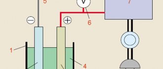
High-speed processing of aluminum (HSO)
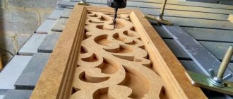
Aluminum milling is a popular and one of the simplest processing technologies. The installed cutter, removing a layer of metal of a given thickness, gives the workpiece the required shape and dimensions.
The use of modern CNC models ensures guaranteed processing with the most accurate implementation of the smallest elements, obtaining 2D or 3D relief of any degree of complexity. All images are processed in detail and clearly.
The economic efficiency of different technologies can vary quite significantly. VSO is, at the moment, the most effective method of processing aluminum workpieces. This is explained by the fact that a high spindle speed is organically combined with the possibility of increasing (in such modes) the depth of cut. Example. For steel this figure does not change.
In a number of situations, it is more economically feasible to manufacture one part (with a significant percentage of processing waste) than to cut out several parts from the same volume of material. This is precisely what explains the demand for processing VSO modes.
Ways to improve machine efficiency
If you plan to process plastic on a milling machine, it is recommended to use blanks obtained by casting. The melting point of such parts is higher, which reduces the risk of damage during processing. The most optimal mode for cast plastic workpieces is counter milling.
When working with acrylic or aluminum, cutting fluids should be used. The most acceptable option is a universal technical lubricant. If it is missing, you can cool the instrument using ordinary water. Similar requirements for polystyrene.
If the cutter becomes dull during processing of an acrylic part, it is necessary to reduce the speed. Reduction must be carried out before chipping occurs. The lower the speed, the more load the cutting mechanism receives. Therefore, the described task must be performed carefully, otherwise there is a risk of damage to the milling machine. This must be taken into account by those who have previously cut incorrectly.
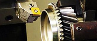
Cutting aluminum on a CNC milling machine
Modern CNC machines make it possible to carry out the aluminum cutting procedure with the highest possible accuracy and quality, giving the sheets the desired shape and required size.
High technological efficiency of the process is ensured thanks to the development of machine tool industry. When performing milling work on cutting aluminum using CNC machines, skills in working with industrial equipment and specific knowledge in metal processing are required. When using technology in production, the owner’s costs for training employees to work in SCADA applications are significantly reduced. To work, it is enough to create codes based on pre-compiled drawings directly on the machine screens. To do this, you only need to correctly set the coordinates and dimensions of the part, as well as the direction of movement of the cutting tool.
The system independently controls the production process, so the finished product is ideal in terms of geometry.
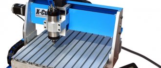
3D milling machine Advercut K45MT/2040
- Power requirements 380V (220V)
- USB 2.2 connection interface
- XY Motion Gear Rack (Helical) / Taiwan
- Height Z, mm 200 (300)
- Dimensions, mm 2150 x 3150
- Drive motors Stepper (optional)
- Control code G code
- Linear guides Linear rail / Taiwan
- Max. processing speed, mm/min 35000
- Spindle power 3.5-7.5 kW, 18000 rpm
- Axes 3
- Spindle cooling Air
- Supported software Type3 Software/France (included, license), as well as ArtCAM, Ucancam, etc.
- Working field 2000 x 4000 x 200 mm
- Resolution, mm 0.01
- Control system DSP0501
- Collet chuck ER25
- Price 1,328,000 rub.
Go to product
Cutting aluminum sheets on computer-controlled machines is a reliable way to ensure high productivity and quality of finished products.
Table: cutting speed of materials
| Material | Speed (meters per minute) |
| Aluminum | from 200 to 400 |
| Brass | from 150 to 300 |
| Bronze | from 100 to 150 |
| Bakelite | from 50 to 100 |
| PVC | from 100 to 200 |
| Thermoplastics | from 300 to 500 |
| Various types of wood | from 300 to 500 |
| Stainless steel | from 50 to 90 |
The table contains general values for most machine tools, but they may go beyond the specified scope depending on the modification of the milling machines and the characteristics of the material. For example, plywood has a lower stiffness rating than wood, so standard speed values will not work.
Immersion and cutting edge
Milling should be performed using a drilling method similar to drilling. If the end does not touch the material being processed, it is necessary to reconfigure. Due to differences between the edges of the passage, the quality of processing of the sides differs. Recommended:
- mill internal contours clockwise;
- mill external contours counterclockwise.
Thanks to milling using this system, the lower quality side will be cut off.
Important! The deeper the dive, the higher the likelihood of failure. At high speed, the cutter should plunge to a minimum depth, and cutting should be performed in several passes.
Left-hand cutters
Problem:
The 2-flute cutter melts PVC foam.
Solution:
choose a lower number of revolutions or mill with a single-thread cutter. (Picture)
1. Dive:
The cutter must be able to penetrate the material with its end (drilling function).
2. Cutting edge:
As a rule, the edges of the passage differ from each other.
The opposite side of movement is “more beautiful” than the side of synchronicity. This is especially noticeable when using a 1-flute cutter, as well as when milling aluminum. Advice;
Mill the inner contours clockwise, the outer contours counterclockwise. Thus, the “bad” side ends up in the chips
3. Chip removal:
The chips must be discharged quickly so that the cutter cavities do not fill, causing the cutter to break. The deeper and faster the milling occurs, the more difficult it is to remove chips. Directions: Do not rout deeper than double or triple the cutter diameter. Go through deeper grooves in several passes. When milling polystyrene and other plastics, it makes sense to use cutters with polished grooves for better output.
4. Heat dissipation/lubrication:
The cutter should not become too hot: On the one hand, a tool with too high a temperature loses its properties, on the other hand - even more critical - plastic and aluminum chips can “stick” in the grooves, preventing the removal of chips and, as a result, lead to breakage of the cutter. When processing metals, it is imperative to recommend a lubricant. Note: Aluminum and non-ferrous metals can be milled with alcohol or special emulsions; when processing plexiglass, soapy water can be used.
5. Risk of breakage:
grows linearly with increasing feed and increasing immersion depth: Double feed means double fractional risk, double immersion depth means eight-fold fractional risk.
Directions:
It is better to mill in several passes less deeply and at a higher feed rate. Use a router bit with the shortest cutting length possible. Tighten it as much as possible. General rule: one third of the total length of the cutter is clamped in the chuck (chuck collet).
The right cut brings the chips to the top.
A right-hand cutter facilitates the removal of chips to the top, which is good for continuous removal; however, it has the disadvantage that the cutter, like a corkscrew, also moves the base material (workpiece) upward, “swirls” when milling wood or “buries” when processing thin sheet material ( for example tin). A cutter with a left helix on the contrary pushes down on the material and when routing fibrous materials such as wood or cardboard, you achieve a smoother top edge (the fibers are not lifted, but “pressed” into the base material). But here the negative factor is the difficulty of removing chips.
Note:
In standard cases, use a right-hand cutter. Left-hand cutters are advantageous for shallow cuts in thin materials, where the danger of right-hand cut “burrowing” and jerking the workpiece upward is great. However, the harder the material you use, the sooner you can abandon the left helix cutter.
A. Right-hand cutting (normal form): Brings the chips to the top. The cutter has a tendency to "burrow" and lift up the base material. "corkscrew effect"
B. Left helix (special shape): Guides chips down when machining from the end, or used when working in an already milled cavity. The cutter presses down on the base material (the opposite of the “corkscrew effect”). Not suitable for deep milling.
Heating and Lubrication
As the temperature rises and chips stick, the cutter loses its performance characteristics and works worse. To avoid breakage or damage to wood or other materials, it is recommended to lubricate the operating mechanisms.
Required for use:
- alcohol and special emulsions - when cutting or drilling aluminum and non-ferrous metals;
- soapy water - when processing parts that contain plexiglass.
In this case, it is necessary to control the feed and its speed. Determination of optimal values is carried out depending on the material and its thickness. To configure the desired indicator, use the values from the table.
Type of cutter: 1 or 2 blades?
In advertising production
Most often, 1 and 2-flute cutters are used, less often 3-flute cutters.
Four-blade or multi-blade cutters cannot cut thick chips in soft materials and are generally not used. Their main problem when milling soft
materials is “baking” in the cavities of the cutter. Single-flute cutters provide better chip evacuation due to a more spacious cutter flute. Special cutters for aluminum have a large groove. Particularly advantageous when machining soft aluminum, in addition to polished cutters, are coatings with Titan-Nitrid (TiN).
The choice of the “ideal” type of cutter always depends on the material being processed:
When milling “soft” materials:
soft plastics (PVC, plexiglass, polystyrene foam), wooden materials (wood, fiberboard, plywood, chipboard), soft grades of aluminum and sandwiches (aluminum / plastics) benefit from sharp 1-flute cutters.
Since here the problem of faster dulling is preferable to the risk of clogging and breakage of the cutter. For hard plastics,
sharp 2-way ones with a fishtail profile are suitable.
When machining harder metals
such as brass, we can recommend 2-flute cutters with a flat grind.
When milling extremely rigid structural steel
or very high-quality steel, three or four entry cutters are used.
Cross-cut single cutter Single blade leaves large open space for chip evacuation
Three-flute cutter in cross section Three blades significantly reduce the space for chip evacuation
Differences between a cutter and an engraver
Many people use the terms “Cutter” and “Engraver” interchangeably. However, we are talking about two different tools. An engraver is a simple tool, splitting a cylinder in half, followed by a back grind. The shape may vary; the most common are triangular. Unlike milling cutters, they do not have a spiral chute to drain chips.
Milling cutter material: HSS or carbide?
In advertising technology, carbide cutters are predominantly used. Carbide (HM) is an expensive, man-made product that is agglomerated from fine powders (e.g. Wolfram-Carbid). During the agglomeration process, the shape of the cutter is immediately created and subsequently does not change (it is only sharpened). Carbide is extremely hard and wear-resistant, however, it is susceptible to vibration and shock. It is important when using HM cutters to have a stable, possibly heavier and more massive machine, a spindle with precise rotation and high-quality clamping collets. The material to be milled must be rigidly and motionlessly fixed on the machine. High speed steel (HSS) is used primarily where carbide is too sensitive: when milling stainless steel sheets, on shaky machines, or in cases where the clamping rigidity is not sufficiently ensured. HSS wears out much faster, but there is less risk of premature failure due to its viscosity. The life of a coated HSS cutter is significantly increased. For example, titanium nitride (TiN) increases service life by six times. Titan-Nitrid is significantly stiffer than HSS and also stiffer than HM. With Titan-Nitrid coating, HM tools also last longer, although the difference in hardness is negligible. The coverage has a more significant effect on the number of revolutions and feed. It can be increased and thus the processing time can be shortened. When milling aluminum, TiN prevents the dreaded baking of aluminum in the cutter. The coating acts like Teflon in a frying pan (the chips slide)
Tables: feed speed
| Material | Speed for 3mm face tool (in millimeters per minute) | Speed for 6mm face tool (in millimeters per minute) |
| Soft woods | from 1 to 1.5 thousand | from 2 to 3 thousand |
| Solid wood | from 0.5 to 1 thousand | from 1.5 to 2.5 thousand |
| Double layer plastic | 2 thousand | absent |
| Acrylic and different types of polystyrene | from 0.8 to 1 thousand | from 1 to 1.3 thousand |
| PVC | from 1.5 to 2 thousand | from 1.5 to 2 thousand |
| Aluminum alloys | from 0.5 to 0.8 thousand | from 0.8 to 1 thousand |
The values in the table indicate the minimum and maximum values at which milling machines can cut properly without risk of failure.
Cutting modes when milling on machine tools
Surface processing of workpieces by milling can be carried out only after the development of a technological map, which indicates the main processing modes. Such work is usually carried out by a specialist who has undergone special training. Cutting conditions during milling can depend on a variety of indicators, for example, the type of material and the tool used. The main indicators on the milling machine can be set manually, and the indicators are also indicated on the numerical control unit. Thread milling deserves special attention, since the resulting products are characterized by a fairly large number of different parameters. Let us consider the features of choosing cutting modes during milling in detail.
Cutter selection
Setting the required modes largely depends on the characteristics of the cutting mill used. The most suitable option is a large diameter solid carbide cutter. It is expensive, but has a number of advantages:
- high accuracy rate;
- high-quality heat dissipation;
- high cutting and feed speed.
For a specific machine model, it is necessary to use cutters made by the manufacturer. Less expensive manual options can only harm the machine tool.
Selecting a mode depending on the type of cutter
To obtain the same product, a variety of types of cutters can be used. The choice of basic milling modes is carried out depending on the design and other features of the product. Cutting modes when milling with disk cutters or other design options are selected depending on the following points:
- The rigidity of the system used. An example is the features of the machine and various equipment. The new equipment is characterized by increased rigidity, which makes it possible to use higher processing parameters. On older machines, the rigidity of the system used is reduced.
- Attention is also paid to the cooling process. Quite a large amount of equipment provides for the supply of coolant to the processing zone. Due to this substance, the temperature of the cutting edge is significantly reduced. Coolant must be supplied to the material removal zone continuously. At the same time, the resulting chips are also removed, which significantly improves cutting quality.
- Processing strategy also matters. An example is that the production of the same surface can be carried out by alternating various technological operations.
- The height of the layer that can be removed in one pass of the tool. The limitation may depend on the size of the tool and many other geometric features.
- Size of processed workpieces. Large workpieces require a tool with wear-resistant properties that will not heat up under certain cutting conditions.
Taking into account all these parameters allows you to select the most suitable milling parameters. This takes into account the distribution of allowance when milling with spherical cutters, as well as the features of processing with an end mill.
The classification of the instrument in question is carried out according to a fairly large number of characteristics. The main thing is the type of material used in the manufacture of the cutting edge. For example, the VK8 cutter is designed to work with workpieces made of hard alloys and hardened steel. It is recommended to use this design option at low cutting speeds and sufficient feed. At the same time, high-speed cutters can be used for processing with a high cutting rate.
As a rule, the choice is made taking into account common tables. The main properties are:
- Cutting speed.
- Type of material being processed.
- Type of cutter.
- Speed.
- Innings.
- Type of work performed.
- Recommended feed per tooth depending on the cutter diameter.
The use of regulatory documentation allows you to select the most suitable modes. As previously noted, only a specialist should develop the technological process. Mistakes made can lead to tool breakage, a decrease in the quality of the workpiece surface and errors in the tools, and in some cases, equipment breakdown. That is why you need to pay a lot of attention to choosing the most suitable cutting mode.