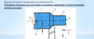
Cutting modes in machining are a set of operating parameters that determine the speed, force and depth to which the cutter is immersed into the part during the process of removing a layer of metal from its surface.
Their basic values are determined by calculation based on the geometry of the cutting edge of the tool and the workpiece, as well as the speed of their approach. Real metal processing processes are influenced by many factors related to the characteristics of the tool used, machine equipment and the material being processed.
Therefore, empirical formulas are used to calculate technological cutting conditions. And the basic values are included in their composition along with such reference values as groups of correction factors, durability values, parameters of processing conditions, etc.
Cutting modes affect not only the specified accuracy and processing class of the product. They determine the force with which the tool edge acts on the metal, which directly affects power consumption, the level of heat generation and the wear rate of the tool.
Therefore, the calculation of their parameters is one of the main tasks of technological services of enterprises. Despite the many varieties of metal-cutting equipment and tools, all machining is based on common principles.
Therefore, methods for calculating cutting modes are unified and systematized into three main groups: for turning, for drilling and for milling. All other types of calculations are derivative.
The second most common type of machining after turning is drilling. It is also equivalent to reaming, countersinking, and drilling. When calculating cutting conditions, one can, neglecting the rigidity of the processing system, imagine that this is simultaneous boring with several cutters, so the calculation principle will be similar to turning. However, for small drill diameters, less than 10 mm, cutting modes are calculated based on the integrity of the drill after processing. In other words, the modes are calculated in such a way that the drill does not break, so the calculation is made based on the strength characteristics of the tool.
However, during experiments with the technique, an error was identified due to which the cutting speed was too high, this was expressed by the duration of drilling, but high tool life, and high quality of processing. Whether this is a plus or a minus must be decided for a certain task, since low feeds can cause the cutting part to quickly become dull (or even stick), but at too high feeds, the tool is likely to break, not to mention reducing the safety of processing.
Our methodology for calculating drilling modes can be found below. In the corresponding forum topic you can download a macro for automatically calculating cutting conditions for drilling work.
Methodology for calculating cutting conditions during drilling operations
When drilling, it is recommended to set modes based on the power of the equipment used. The most convenient cutting tool material is high-speed steel (P18, P6M5). Feed rates during drilling operations are calculated using the formula:
S-feed, mm/rev
D - drill diameter, mm
C-coefficient, depending on the material being processed and other technological factors (surface cleanliness, presence of further processing, etc.) (Table 1)
Kls is the feed coefficient, depending on the chip exit condition (Table 2)
| Processed material | NV | Feed group determined by technological factors | ||
| I | II | III | ||
| Steel | ≤160 | 0,085 | 0,063 | 0,042 |
| 160-240 | 0,063 | 0,047 | 0,031 | |
| 240-300 | 0,046 | 0,038 | 0,023 | |
| >300 | 0,038 | 0,028 | 0,019 | |
| Cast iron | ≤170 | 0,130 | 0,097 | 0,065 |
| >170 | 0,078 | 0,058 | 0,039 | |
| Non-ferrous metals | Soft | 0,170 | 0,130 | 0,085 |
| Solid | 0,130 | 0,097 | 0,065 | |
Table 1
Feed group I - drilling blind holes or drilling without tolerance according to the 5th accuracy class or for subsequent drilling
Group II feed-drilling of blind and through holes in parts of non-rigid structure, drilling for threads and reaming for subsequent processing with a countersink or reamers
Group III feed - drilling of blind and through holes and drilling for further processing
| Hole length in diameters up to | 3 | 4 | 5 | 6 | 8 | 10 |
| Kls coefficient | 1.00 | 0.95 | 0.90 | 0.85 | 0.80 | 0.70 |
table 2
Cutting modes when drilling
The power consumed when drilling depends on the torque. Torque is calculated using the formula:
Mkr - torque perceived by the drill when cutting, N*m
Cm, q, y - coefficients for torque during drilling, depending on cutting conditions (Table 3)
D - drill diameter, mm
S-feed, mm/rev
Kmr is the coefficient for torque, depending on the mechanical properties of the material (Table 4)
| Processed material | Cm | q | y |
| Structural carbon steel, | 0,0345 | 2,0 | 0,8 |
| Gray cast iron 190 HB | 0,021 | 2,0 | 0,8 |
| Copper alloys | 0,012 | 2,0 | 0,8 |
| Aluminum alloys | 0,005 | 2,0 | 0,8 |
Table 3
| Processed material | KMR | Indicator n | ||
| Steel | C ≤0.6% | -1,0 | ||
| 1,75 | ||||
| 1,75 | ||||
| chrome steel | 1,75 | |||
| С>0.6% | 1,75 | |||
| Gray cast iron | 1,7 | |||
| Copper alloys | 1 | — | ||
| Aluminum alloys | 1 | — | ||
Table 4
For normal drills with a diameter above 10 mm there is no danger of breaking from excessively high torque, since for these diameters the highest stresses occurring in the drill are usually limited by the rate of dullness as cutting speed and feed increase. For drills with a diameter less than 10 mm, it is recommended to calculate the torque according to
to ensure instrument integrity.
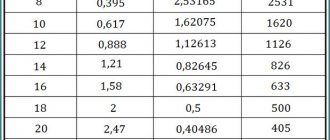
By equating and it is possible to calculate the maximum possible feeds for small-diameter drills when drilling a given material (Table 5).
| Processed material | Steel | Cast iron | Copper alloys | Aluminum alloys |
| Maximum possible feed, mm/rev | 0,01 | 0,019 | 0,037 | 0,11 |
Table 5
To ensure AIDS rigidity when drilling, it is necessary to install the drill in the chuck with the minimum possible overhang (3-5 mm more than the depth of the hole being machined).
The cutting speed when drilling is calculated by the formula:
The rotation speed is calculated using the formula:
Table of calculations of modes when drilling on the 2A135 machine in Appendix 1.
Countersinking and reaming
The feed rate for countersinking and drilling is calculated similarly using the formula:
Torque is calculated using the formula:
Select coefficient values Сm, x, y, q according to Table 6
| Processed material | Cm | q | x | y |
| Structural carbon steel, | 0,09 | 1,0 | 0,8 | 0,8 |
| Gray cast iron 190 HB | 0,085 | 1,0 | 0,8 | 0,8 |
| Copper alloys | 0,031 | 0,85 | 0,8 | 0,8 |
| Aluminum alloys | 0,02 | 0,85 | 0,8 | 0,8 |
Table 6
D - drill diameter
d - diameter of the previously drilled hole
The cutting speed is calculated by the formula:
The rotation speed is calculated using the formula:
Deployment
To determine the reaming torque, each tooth of the tool can be considered as a boring cutter.
sZ - feed per tool tooth (equal to s/Z)
s-feed, mm/rev
Z- number of reamer teeth
Coefficients Сp, x, y in table 7
| Processed material | Cp | x | y |
| Steel | 300 | 1 | 0,75 |
| Gray cast iron 190 HB | 92 | 1 | 0,75 |
| Aluminum alloys | 40 | 1 | 0,75 |
| Copper alloys | 55 | 1 | 0,66 |
Table 7
The cutting speed is calculated by the formula:
The rotation speed is calculated using the formula:
Table of calculations of modes when deploying on a 2A135 machine in Appendix 2.
When introducing the calculation methodology in the TechnoPro system, it is recommended for drilling and reaming to enter the calculated modes into the information database, thereby avoiding programming the calculation conditions and simplifying the operation of the system. To calculate the modes for countersinking and drilling, it is necessary to program the conditions using the coefficients from Table 6.
How to properly drill holes in metal
When working with metal, you cannot do without drilling holes. Working with metal is a complex operation. This is due to the fact that metal parts have high strength, for the processing of which special equipment and technologies must be used.
You may need to drill holes in any field and when performing work in the country, at home or in the garage. Even when repairing a car, you have to drill holes in the metal. If you are going to do the work away from the workplace, you will need an electric drill or hammer drill with an adapter chuck for the drill, as well as a core or tap to center the hole.
If you need to make holes in small parts, it is better to use a drill press. On it you will be sure of the correct direction of the drill and the drilling speed.
Conquering a tree
Before you start drilling wood, you can make a small indentation with an awl in the marked place to prevent the drill from slipping, or use equipment with a centering point.
When working on wood, to prevent chips and burrs at the exit, you can use tape or adhesive tape, sealing the place of the intended exit with them and removing them only after obtaining a hole. For the same purpose, you can place a wooden block under the output surface.
You can also use double-sided counter-drilling, excluding the exit of the drill as such, but in this case it is necessary to accurately calculate the location of the intended exit in order to obtain a hole with a smooth stroke.
We work with glass and tiles
To make holes in glass and tiles, use special drill bits with a conical carbide tip. To prevent slipping from the intended point of starting drilling, stick insulating material on this place; the glaze on the tile may slightly chip off. Cool the drill and surface constantly using water, vinegar or turpentine. Work with glass and ceramic tiles only at low engine speeds, avoiding damage to seams and joints.
Power and speed when working with metal
An important factor is the choice of tool, namely a hammer drill, drill or screwdriver, which will be used to make holes in the metal. If you use a drill with a power of up to 700W, you will not be able to make a large hole right away. A hand drill with a power of up to 700W is best used for drilling holes with a diameter of up to 10-13mm.
It is important to choose the correct speed of the drill or screwdriver. After all, at high speeds, your drill will simply burn out. This way you will ruin it.
You need to drill metal at low or medium speeds, not exceeding 500-1000 revolutions.
The larger the diameter of the drill you are working with, the lower the speed you need to choose.
Basics of drilling
To make holes, two things can be useful - securely securing the workpiece and rigidly fixing the drill. To obtain holes in the workpieces, it is necessary to ensure their reliable fixation in a vice and first mark the location of the intended hole. You need to start this process at low speeds, gradually increasing the speed. It is also better to finish at low speeds.
When manual (not fixed) drilling, you must hold the drill perpendicular to the work surface. The less movement of the drill to the sides, the more the diameter of the hole corresponds to the diameter of the drill.
By securing the drill to a fixing stand, you can prevent unnecessary vibrations of the device. This also allows the use of high-power drills to produce large-diameter holes in materials of various thicknesses and densities.
If the drill jams, stop working. If the drill is equipped with a reverse function, then using it, carefully remove the equipment. If there is no reverse, a stuck drill can be freed using pliers and a hammer. To avoid jamming of the equipment at the exit, use low speeds and reduce the pressure on the drill. The depth of blind holes can be controlled using a drill depth limiter, which most often comes with the drill.
Which drill to choose for drilling metal
One of the first questions that inexperienced craftsmen ask is which drill to drill into metal? In fact, answering correctly is not so easy. For metal processing, you need to use special drills made of high-speed tool steel. The cutting part in them is made with the addition of titanium nitride.
When choosing drills for drilling metals, the main and running ones are drills made of high-speed tool steel; they can be found in the store by the HSS .
When working with cast iron, stainless steel and other metals that are difficult to machine, you should use carbide drills. Their disadvantage is their very high price, which makes the work expensive.
If you choose drills with one of the best cutting properties, it will be a tool with the addition of cobalt, marked P6M5K5. This is the best value for money.
Is it possible to drill metal with a concrete drill?
There may be an urgent need to make a hole in metal, and only a concrete drill is at hand. On such a drill, the tip is made of pobedite, which makes it possible to drill concrete and brick with a hammer. You cannot use such a drill to drill a hole in metal. You may lick off the tip of the drill bit, especially if you try to use a large diameter drill bit or drill through thick metal. To sum it up, you won’t be able to drill through metal with a Pobedit drill.
However, if you sharpen it at the right angle, it is possible to drill into metal.
We are friends with metal
When working with metal, to prevent the drill from wandering at the beginning of work, it is necessary to make a recess with a core (punching), or use drills with a small (stepped) diameter of the cutting head. Such equipment eliminates the need for core punching and does not leave burrs at the exit of the metal.
When working with sheet metal, for convenience, place a wooden board or block under the sheet. This will reduce the indentation of the metal around the hole and reduce the number of burrs at the exit. The sharp edge of the hole (burr) that forms on the exit surface can be removed using a countersink or a special deburring device. To obtain holes of large diameter, you can use a drill of a smaller diameter during the initial passage, and then drill the resulting hole with a drill of the required diameter.
Constant cooling will help extend the life of the drill and prevent overheating and breakage. Use oil or plain water as coolant.
We process concrete
A hammer drill is still recognized as a traditional tool for drilling concrete. However, if the volume of work is not so large, an impact drill can be a successful competitor.
In the absence of one, pliers and a hammer will help us again. Periodically interrupting the process of working with a conventional drill, remove the drill, insert a metal punch into the hole and, holding it with pliers, apply several blows with a hammer. These actions cause microcracks in the concrete at the bottom of the hole and allow the drill bit to pass through the material more easily.
When working with concrete, stone or brick, use special drills with carbide inserts. Be sure to monitor the cooling of the equipment, although, according to some sources, water cooling reduces their service life, so it would be advisable to use dry drilling with temporary breaks for air cooling.
When drilling a heterogeneous material (for example, reinforced concrete), it is better to use two types of drills (for concrete and for metal) to reduce the risk of changing the hole path and damaging the equipment. To prevent drills from overheating, it is necessary to periodically cool them using water or lubricating oil.