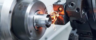
Machining metal and other surfaces using a lathe has become an integral part of everyday life in the industry. Many technologies have changed, some have become simpler, but the essence remains the same - correctly selected cutting modes during turning provide the required result. The process includes several components:
- power;
- rotation frequency;
- speed;
- processing depth.
Key manufacturing points
There are a number of tricks that must be followed while working on a lathe:
- fixing the workpiece into the spindle;
- turning using a cutter of the required shape and size. The material for metal-cutting bases is steel or other carbide edges;
- Removal of unnecessary balls occurs due to different rotation speeds of the caliper cutters and the workpiece itself. In other words, a speed imbalance is created between the cutting surfaces. Surface hardness plays a secondary role;
- the use of one of several technologies: longitudinal, transverse, a combination of both, the use of one of them.
Chemical composition of steel 45
In many ways, performance and other qualities are determined by the chemical composition. This is due to the fact that some elements can significantly increase strength, while others increase fragility. The chemical composition of steel 45 is characterized by the presence of the following elements:
- The main chemical elements of St 45 are iron and carbon. The concentration of the second element largely determines how strong and hard the product is. Established standards specify that the carbon concentration should be from 0.42 to 0.5%. At the same time, the metal composition is about 97%.
- The composition includes a relatively small amount of alloying elements. The main ones can be called magnesium and silicon. Their concentration rate is more than 0.1%.
- The concentration of other elements is maintained within a certain range. For example, GOST defines a small amount of sulfur and phosphorus, since these elements lead to deterioration in performance.
The carbon content, like many other elements, is maintained within a certain range. This element largely determines the main characteristics of the resulting products; too high a concentration can lead to surface hardness and structure fragility.
Types of lathes
For each specific part, one or another unit is used:
- screw-cutting and turning: a group of machines that are in greatest demand in the manufacture of cylindrical parts from ferrous and non-ferrous metals;
- rotary-turning: types of units used for turning parts. Especially large diameters from metal blanks;
- lobe lathe: allows you to turn parts of cylindrical and conical shapes with non-standard dimensions of the workpiece;
- turret-turning group: production of a part, the workpiece of which is presented in the form of a calibrated pond;
- CNC - numerical control: a new type of equipment that allows you to process various materials with maximum precision. Experts can achieve this using computer adjustment of technical parameters. Turning occurs with an accuracy of micron fractions of a millimeter, which cannot be seen or verified with the naked eye.
Selection of cutting modes
Operating modes
A workpiece made from each specific material requires compliance with the cutting mode during turning. The quality of the final product depends on the correct selection. Each specialized specialist in his work is guided by the following indicators:
- The speed at which the spindle rotates. The main emphasis is on the type of material: rough or finishing. The speed of the first is slightly less than the second. The higher the spindle speed, the lower the cutter feed. Otherwise, melting of the metal is inevitable. In technical terminology, this is called “ignition” of the treated surface.
- Feed – selected in proportion to the spindle speed.
Cutters are selected based on the type of workpiece. Grooving using a turning group is the most common option, despite the presence of other types of more advanced equipment.
This is justified by low cost, high reliability, and long service life.
Chemical composition and decoding
Grade 45 is included in the group of high-quality structural steels. The number “45” means the carbon content of the steel in hundredths of a percent.
The quantity and type of chemical elements in its composition are regulated by GOST 1050-72. The main components are carbon and iron. Carbon imparts greater hardness, the ability to be strengthened by heat treatment, and increases machinability.
In addition to the basic elements, grade 45 steel contains the following components:
- Harmful impurities of phosphorus (up to 0.035%) and sulfur (up to 0.04%) have a negative effect on mechanical properties. Their larger molecules are embedded in the crystal lattice of steel and weaken its strength and wear resistance. In addition, the increased content of phosphorus and sulfur causes red brittleness in steels, i.e. formation of cracks during pressure treatment.
- Beneficial impurities of manganese (0.5-0.8%) and silicon (0.17-0.37%) reduce the internal stress of steel, thereby reducing the likelihood of cracks. Helps increase the effectiveness of hardening from heat treatment. In general, their presence has a positive effect on the ductility of steel.
- Also, 45 steel contains impurities of nickel, chromium, copper and arsenic. The total content of all these elements does not exceed 0.7%. For this reason, their influence on the properties of steel is insignificant.
It is worth noting that the presence of the above-mentioned by-products is associated with imperfect smelting technology and the quality of the chemical composition of the charge.
Analogs
Marking 45 is widespread outside of Russia and has many foreign analogues. Among them are:
- 1044, 1045 U.S.
- 1.0503 Germany.
- S45C Japan.
How is speed calculated?
In an engineering environment, the calculation of cutting conditions is calculated using the following formula:
V = π * D * n / 1000,
Where:
V – cutting speed, calculated in meters per minute;
D – diameter of the part or workpiece. Indicators should be converted to millimeters;
n – the value of revolutions per minute of time of the processed material;
π – constant 3.141526 (tabular number).
In other words, the cutting speed is the distance that the workpiece travels in a minute.
For example, with a diameter of 30 mm, the cutting speed will be 94 meters per minute.
If it becomes necessary to calculate the speed, given a certain speed, the following formula is applied:
N = V *1000/ π * D
These values and their interpretation are already known from previous operations.
Recommended feeds when processing metals according to the method of V. A. Kolesov (according to Uralmashplant)
Note. Smaller feed values are given for more durable materials, larger ones for less durable ones.
Cutting speed
The cutting speed depends mainly on the material being processed, the material and tool life, cutting depth, feed and cooling.
Based on the experience of high-speed turners at leading factories and laboratory research, special tables have been developed from which you can select the required cutting speed when machining with carbide cutters.
As an example in table. Table 6 shows the recommended cutting speeds for various cutting depths and feeds when longitudinal turning of structural carbon and alloy steels with tensile strength sigmab = 75 kg/mm² using T15K6 carbide cutters.
Cutting speeds indicated in table. 6, are designed for certain cutting conditions. They provide for the turning of steels σb = 75 kg/mm² using T15K6 carbide cutters with a leading angle φ = 45° with a cutter life T = 90 min.
Under conditions different from those indicated in table. 6, the tabular data on cutting speed should be multiplied by the corresponding coefficients given below.
Coefficients that take into account the strength of the material being processed: Coefficients that take into account the durability of the cutter: Coefficients that take into account the grade of carbide:
Table 6
Cutting modes when turning structural and alloy steels with tensile strength
σb = 75 kg/mm²
with cutters with T15K6 inserts
Requirements for modern lathes
Lathes designed for high-performance turning are subject to higher demands than conventional lathes.
When working at high cutting speeds, there is a danger of vibrations due to insufficient rigidity of the machines, the presence of excessive clearances in the spindle bearings and in the movable joints of the support, and unbalance of individual rapidly rotating parts of the machine, chuck or workpiece.
Consequently, for quiet, vibration-free operation of the machine, its individual parts (spindle, support, tailstock) must have sufficient rigidity, and the rotating parts must be carefully balanced.
The power of a lathe for high-speed cutting must be greater, since the higher the cutting speed, the greater the electric motor power required.
These requirements are met by machines produced by the domestic machine tool industry, for example, the 1A62 screw-cutting lathe, which we examined in detail, the 1K62 machine, etc.
However, for high-performance cutting, in some cases it is possible to use old-model lathes available in factories, with some modification of their main components.
This kind of alteration of machines is called modernization
.
Conversion of existing machines for high-performance cutting in some cases comes down mainly to increasing the spindle speed and replacing the existing electric motor with a more powerful one; in other cases, more complex alterations are required, for example, it is necessary to change the design of the friction clutch, the main drive, add devices for forced lubrication of the spindle, strengthen individual parts of the machine, etc.
Increasing the spindle speed is one of the widely used measures when converting machine tools to high-speed cutting and is achieved by changing the diameters of existing pulleys. At the same time, the electric motor is also replaced with a more powerful one. The flat-belt transmission from the electric motor to the machine is replaced by a V-belt (see Fig. 2, b). This transmission allows you to obtain the required increased power and a higher gear ratio without changing the width of the pulley.
Machines transferred to high-speed processing must be thoroughly checked and, if necessary, repaired. When repairing, you should pay attention to the headstock bearings, friction clutch, caliper, etc. The spindle bearings must be carefully adjusted, and the gaps in the moving parts of the caliper are eliminated by tightening the wedges. The friction clutch must be checked and, if necessary, strengthened accordingly. The machine should always be well lubricated, especially its gearbox.
Secure installation of the machine on the foundation is a prerequisite for avoiding vibrations, especially for machines with unbalanced rotating parts.
Control questions
1. Explain the procedure for selecting cutting depth and feed. 2. Select the cutting speed when turning structural steel σb = 75 kg/mm² at a depth of cut t - 3 mm with a T15K6 carbide cutter, using the table. 6, taking feed s = 0.2 mm/rev. 3. Select the cutting speed when turning σb = 50-60 kg/mm² at a depth of cut t = 2 mm with a T5K10 carbide cutter at a feed s = 0.25 mm/rev. 4. Select the cutting speed when turning alloy steel σb = 100 kg/mm² at a depth of cut t = 1 mm with a T30K4 carbide cutter at a feed s = 0.15 mm/rev and with a cutter life of 30 minutes. 5. What basic requirements must a high-speed cutting lathe satisfy? 6. What is called machine modernization? 7. List the main ways to modernize existing machines for high-speed cutting.
| Previous page | table of contents | Next page |
Additional materials
During manufacturing, most specialists are guided by the following indicators as an additional guide. Strength coefficient table:
| Workpiece material | Strength limit | Brinell hardness scale | Coefficient, MPa |
| alloy and carbon steel | varies from 400–1100 units | – | 1500–2600 |
| cast iron and also gray | – | 1400–2200 | 1000–1200 |
| bronze | – | – | 600 |
| silumin | – | – | 450 |
| duralumin | tensile strength from 250 to 350, but often higher depending on the quality of the workpiece | – | 600–1100 |
Material strength coefficient:
| Steel, kg/mm | Indicator value |
| 50,1–60,1 | 1,61 |
| 60,1–70,3 | 1,27 |
| 70,3–80,1 | 1,1 |
| 80,3–90,1 | 0,87 |
| 90,3–100,1 | 0,73 |
| Cast iron, kg/mm | Indicator value |
| 140,1–160,3 | 1,50 |
| 160,1–180,1 | 1,21 |
| 180,1–200,3 | 1,1 |
| 200,3–220,3 | 0,83 |
Cutter life coefficient:
| Duration value, minutes | Index |
| 27–30 | 1,27 |
| 43–46 | 1,11 |
| 57–60 | 1,09 |
| 83–90 | 1,03 |
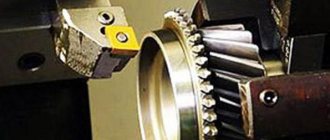
Turning tools: classification
The accuracy of the resulting dimensions and processing productivity largely depend on the quality and reliability of turning tools. They must provide:
- obtaining the required form;
- dimensions;
- surface quality;
- the greatest productivity with minimal power, and therefore energy costs;
- manufacturability in manufacturing;
- possibility of restoring cutting properties;
- minimal consumption of expensive tool materials.
Turning cutters can be classified according to the processing method:
- checkpoints;
- pruning;
- cutting;
- slotted;
- fillets;
- threaded;
- shaped;
- boring
Based on the material of the cutting part there are:
- instrumental;
- high-speed;
- carbide:
- single-carbide (tungsten);
- two-carbide (titanium-tungsten);
- tricarbide (titanium tantalum tungsten);
- mineral ceramic;
- diamonds.
According to their design, turning tools are:
The choice of the type of turning cutter depends on the type of surface being processed (external, internal), the hardness of the workpiece material, the type of processing (roughing, semi-finishing, finishing), geometric parameters and the material of the cutting part and holder.