Here are useful formulas and definitions needed for milling: machining process, cutters, milling methods, etc. Knowing how to correctly calculate cutting speed, feed per tooth, and metal removal rate is critical to obtaining good results in any milling operation.
| Parameter | Meaning | Metric units | Inch units |
| ae | Milling width | mm | inch |
| ap | Axial cutting depth | mm | inch |
| DCap | Cutting diameter at cutting depth ap | mm | inch |
| Dm | Processable diameter (part diameter) | mm | inch |
| fz | Feed per tooth | mm | inch |
| fn | Feed per revolution | mm/rev | inch |
| N | Spindle speed | rpm | rpm |
| vc | Cutting speed | m/min | ft/min |
| ve | Effective cutting speed | mm/min | inch/min |
| vf | Minute feed | mm/min | inch/min |
| zc | Effective number of teeth | PC. | PC. |
| hex | Maximum chip thickness | mm | inch |
| hm | Average chip thickness | mm | inch |
| kc | Specific cutting force | N/mm2 | N/in2 |
| PC | Power consumption | kW | hp |
| Mc | Torque | Nm | lbf/ft |
| Q | Metal removal rate | cm3/min | inch3/min |
| KAPR | Main plan angle | hail | |
| PSIR | Leading Angle (inch) | hail | |
| BD | Case diameter | mm | inch |
| DC | Cutting diameter | mm | inch |
| L.U. | Working length | mm | inch |
Factors affecting machine performance
The choice of appropriate modes depends on a number of factors. For a CNC milling type machine, the most important factors are:
- spindle feed and rotation speed - the permissible rate is calculated depending on the capabilities of the cutting machine, the type of material being processed, as well as the complexity of the part;
- milling width - this indicator is adjusted based on the dimensions of the workpiece (exact data can be found in the drawing);
- milling depth - depends on the number of passes of the cutter (for simple milling on a machine, one pass is usually sufficient);
- cutting speed - the indicator is calculated based on the distance that the cutter travels on wood or other material within one minute (the speed is also set depending on the technical parameters of the workpiece);
- feed – an indicator of spindle movement along three axes;
- feed per minute - calculated to determine the time it will take the spindle to complete the task.
To set up modes and obtain the necessary information, it is recommended to use the instructions for the machine, as well as the permissible values and characteristics of the processed materials in the tables.
Depth
This is what layer the cutter enters the material. Peculiarities:
- Dependence on density and other characteristics of the workpiece.
- During rough metalworking, the cut-in is large, but during finishing and finishing, a minimal layer is removed.
- The natural limitation is the size of the cutting edge.
A correctly selected parameter determines:
- procedure performance, processing speed;
- appearance and quality of the resulting surface.
It's not always fast - it's as deep as possible at one time. In many cases, it will be more productive to make 2-3 passes to a smaller depth. This will improve the cut and also maintain the integrity of the cutter for a longer period.
Ways to improve machine efficiency
If you plan to process plastic on a milling machine, it is recommended to use blanks obtained by casting. The melting point of such parts is higher, which reduces the risk of damage during processing. The most optimal mode for cast plastic workpieces is counter milling.
When working with acrylic or aluminum, cutting fluids should be used. The most acceptable option is a universal technical lubricant. If it is missing, you can cool the instrument using ordinary water. Similar requirements for polystyrene.
If the cutter becomes dull during processing of an acrylic part, it is necessary to reduce the speed. Reduction must be carried out before chipping occurs. The lower the speed, the more load the cutting mechanism receives. Therefore, the described task must be performed carefully, otherwise there is a risk of damage to the milling machine. This must be taken into account by those who have previously cut incorrectly.
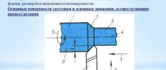
The essence of the process
Milling is a procedure carried out on special machine equipment. During it, a layer (surface or deep, internal part) is removed from the workpiece. During it, various materials can be used, the most popular of which are wood or metal, so we are mostly talking about metalworking.
How the process works. The workpiece is fixed on the bed. Select a suitable cutter or abrasive material, such as a grinding wheel. The equipment produces rotational movements around its axis, as well as movements along two planes. At the same time, longitudinal advancement of the workpiece towards the cutter is possible.
The difference from a lathe is that a milling machine involves rotating the part, that is, circular processing. And in this case, you can grind products of almost any shape, including grinding a smooth surface, making grooves and other holes, including shaped ones. Metalworking can be of two types - rough and finishing. Of course, there are many more stages, but, as a rule, 2 or 3 passes are made. This allows you to create the desired surface profile, such as grooves or teeth.
The movement of the working tool is intermittent. An interesting feature that distinguishes milling from drilling or turning is the position of each tooth during the machining process. They work, come into contact with the surface one at a time, and not all together. This increases the load on each of the edges of the cutter. And only optimization of cutting conditions during milling will help minimize the impact.
Table: cutting speed of materials
| Material | Speed (meters per minute) |
| Aluminum | from 200 to 400 |
| Brass | from 150 to 300 |
| Bronze | from 100 to 150 |
| Bakelite | from 50 to 100 |
| PVC | from 100 to 200 |
| Thermoplastics | from 300 to 500 |
| Various types of wood | from 300 to 500 |
| Stainless steel | from 50 to 90 |
The table contains general values for most machine tools, but they may go beyond the specified scope depending on the modification of the milling machines and the characteristics of the material. For example, plywood has a lower stiffness rating than wood, so standard speed values will not work.
Tips for identifying modes
It is impossible to perfectly select the cutting mode when milling, but you can be guided by the basic principles:
- It is desirable that the diameter of the cutter corresponds to the depth of processing. This will ensure the surface is cleaned in one pass. The main factor here is the material. For those that are too soft, this principle does not apply - there is a risk of removing chips that are thicker than necessary.
- Shock processes and vibrations are inevitable. In this regard, increasing the feed values leads to a decrease in speed. It is optimal to start work with a feed per tooth equal to 0.15 mm/tooth, and adjust it as you go.
- The tool rotation speed should not be the maximum possible. Otherwise there is a risk of reduced cutting speed. Its increase is possible with an increase in the diameter of the cutter.
- Increasing the length of the working part of the cutter and the preference for a large number of teeth reduce productivity and quality of processing.
- Approximate speed values for various materials:
- aluminum – 200-400 m/min;
- bronze – 90-150 m/min;
- stainless steel – 50-100 m/min;
- plastics – 100-200 m/min.
It is better to start at an average speed, and adjust it down or up as you go.
It is important to determine the cutting mode during milling not only mathematically or using special tables. To correctly select and set the optimal parameters for the machine and the desired tool, it is necessary to operate with some features and personal experience
Immersion and cutting edge
Milling should be performed using a drilling method similar to drilling. If the end does not touch the material being processed, it is necessary to reconfigure. Due to differences between the edges of the passage, the quality of processing of the sides differs. Recommended:
- mill internal contours clockwise;
- mill external contours counterclockwise.
Thanks to milling using this system, the lower quality side will be cut off.
Important! The deeper the dive, the higher the likelihood of failure. At high speed, the cutter should plunge to a minimum depth, and cutting should be performed in several passes.
Heating and Lubrication
As the temperature rises and chips stick, the cutter loses its performance characteristics and works worse. To avoid breakage or damage to wood or other materials, it is recommended to lubricate the operating mechanisms.
Required for use:
- alcohol and special emulsions - when cutting or drilling aluminum and non-ferrous metals;
- soapy water - when processing parts that contain plexiglass.
In this case, it is necessary to control the feed and its speed. Determination of optimal values is carried out depending on the material and its thickness. To configure the desired indicator, use the values from the table.
Milling insert parameters
Plate geometry
Important parameters of the insert cutting edge geometry are:
- main rake angle (γ)
- taper angle (β)
Macrogeometry is designed to work in light, medium and heavy conditions.
- Geometry L (for light conditions) has a more positive but weaker edge (large γ angle, small β angle)
- Geometry H (heavy duty) has a stronger but less positive edge (small γ angle, large β angle)
Macrogeometry influences many cutting parameters. An insert with a strong edge can handle higher loads, but it also generates higher cutting forces, consumes more energy, and generates more heat. Optimized geometries have special ISO classification letters.
Plate Top Design
The most important element of the cutting edge for obtaining the required surface quality is the parallel chamfer bs1 or, if applicable, the convex chamfer Wiper bs2, or the corner radius rε.
Tables: feed speed
| Material | Speed for 3mm face tool (in millimeters per minute) | Speed for 6mm face tool (in millimeters per minute) |
| Soft woods | from 1 to 1.5 thousand | from 2 to 3 thousand |
| Solid wood | from 0.5 to 1 thousand | from 1.5 to 2.5 thousand |
| Double layer plastic | 2 thousand | absent |
| Acrylic and different types of polystyrene | from 0.8 to 1 thousand | from 1 to 1.3 thousand |
| PVC | from 1.5 to 2 thousand | from 1.5 to 2 thousand |
| Aluminum alloys | from 0.5 to 0.8 thousand | from 0.8 to 1 thousand |
The values in the table indicate the minimum and maximum values at which milling machines can cut properly without risk of failure.
Milling methods
Linear plunge
Simultaneous translational movement of the tool in the axial and radial directions.
Circular interpolation
Moving the tool along a circular path at a constant z coordinate.
Circular milling with plunging
Moving the tool along a circular path with plunge-in (helical interpolation).
Milling in one plane
Milling with constant z coordinate.
Point contact milling
Shallow radial cutting with round insert or ball end cutters, in which the cutting zone is offset from the center of the tool.
Profile milling
Formation of repeating protrusions during profiling of surfaces with a spherical tool.
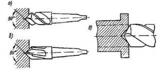
Cutter selection
Setting the required modes largely depends on the characteristics of the cutting mill used. The most suitable option is a large diameter solid carbide cutter. It is expensive, but has a number of advantages:
- high accuracy rate;
- high-quality heat dissipation;
- high cutting and feed speed.
For a specific machine model, it is necessary to use cutters made by the manufacturer. Less expensive manual options can only harm the machine tool.
The classification of cutters depends on the purpose of cutting modes during milling
There are more than 1000 different types of cutters, which can be divided according to numerous parameters and sizes. Its choice directly depends on the rules of movement (rotation speed, direction, presence of counter feed and its power) of the tool. They are also directly determined by the type of metalworking - roughing or finishing. So, let's look at what classifications are carried out:
- according to the workpiece material - there are separate cutters for metal (different for different alloys), wood, plastic and other synthetic substances;
- in the direction of rotation - right-handed and left-handed, by the way, the ease of chip removal depends on this;
- according to design features - alloy, monolithic, folding with the ability to replace cutting parts, etc.;
- in shape - there is a lot of variety here, so listing them all is almost pointless; note that there are round, cylindrical, and conical disk cutters;
- according to the material of manufacture - it can be tool or high-speed steel, carbide metal, carbon or other alloys;
- by purpose - the largest division, which should include end, end, cutting, shaped, and so on.
When choosing the recommended cutting mode, you should especially pay attention to what material the cutting edge is made of, as well as what the cutter is intended for