Principle of operation
What is a voltage stabilizer
The principle of operation of an electric choke is to restrain a sharp increase in current and smooth out the voltage drop line. How an electric choke works can be seen in the example of a fluorescent lamp. To prevent the gas in the flask from burning, but gradually warming up, the coil gradually brings the current to the nominal value.
The incoming current “wastes” its strength to induce a magnetic field around the coil. When the magnetic flux reaches its maximum, the current will begin to flow unhindered through the coil.
The principle of operation of the throttle
Important! Chokes are found in all electrical circuits. Smoothing out the initial electrical voltage protects the radio and electrical components from critical overloads.
How does a transformer work?
Let's consider the operation of a choke assembled on a closed magnetic circuit and connected as a load to an alternating current source. The number of turns and the magnetic permeability of the core are selected in such a way that its reactance is high, but the current flowing in the circuit is correspondingly not.
The current, periodically changing its direction, will excite an electromagnetic field in the winding of the coil (let's call it coil number 1), the direction of which will also periodically change - reversing the magnetization of the core. If an additional coil is placed on the same core (let’s call it number 2), then under the influence of the alternating electromagnetic field of the core, an induced variable E.M.F. will appear in it.
If the number of turns of both coils is the same, then the value of the induced E.M.F. very close to the value of the voltage of the power source applied to coil number 1. If the number of turns of coil number 2 is halved, then the value of the induced E.M.F. will decrease by half, if the number of turns is the opposite, increase - the induced E.M.F. will also increase. It turns out that for each turn there is a certain part of the voltage.
The winding of the coil to which the supply voltage is applied (number 1) is called primary, and the winding from which the transformed voltage is removed is called secondary.
The ratio of the number of turns of the secondary (Np) and primary (Ns) windings is equal to the ratio of their corresponding voltages - Up (primary winding voltage) and Us (secondary winding voltage).
Thus, a device consisting of a closed magnetic circuit and two windings in an alternating current circuit can be used to change the supply voltage - transformation. Accordingly, it is called a transformer.
If you connect any load to the secondary winding, a current (Is) will arise in it. This will cause a proportional increase in current (Ip) in the primary winding. The following ratio will be correct:
Transformers can be used both for converting the supply voltage and for decoupling and matching amplification stages
When working with transformers, you need to pay attention to a number of important parameters, such as: 1. Permissible currents and voltages for the primary and secondary windings
2. The maximum power of the transformer is the power that can be transmitted through it for a long time without causing overheating of the windings. 3. Operating frequency range of the transformer.
Inductive coil device
Magnetic field energy density
The device suppresses pulsations occurring in alternating current. Electrical circuits carry electricity of different frequencies, so low-frequency and high-frequency coils are used to suppress interference.
Low frequency devices
The coils are large. The wire in them is wound around a transformer steel core. In equipment powered by powerful voltage, low-frequency choke units are installed. Inductive coils in cascade design resist sudden changes in current characteristics.
Every electrician knows what electrical throttling is. In industrial enterprises, not a single electrical equipment can do without this.
High frequency elements
The high-frequency electronic choke is much smaller than its low-frequency counterpart. The coil can be made of single-layer or multi-layer winding. For high-frequency chokes, ferrite cores or rods made of magnetic dielectric material are used.
How to calculate the interturn capacitance of the inductor winding?
In the inductor, between the turns, layers and metal objects around the inductor, there is some potential difference that creates an electric field. To assess the influence of this field, the concept of interturn capacitance or the inductor’s own capacitance is introduced, the value of which depends on the size and design features of the inductor.
The interturn capacitance C of the winding, being a parasitic parameter, together with the leakage inductance and the inductor’s own inductance form various types of filters and oscillatory circuits. Although this parameter is of small importance, nevertheless, in certain conditions it has to be taken into account, but accurate calculation is difficult due to the large influence of various design parameters, primarily, the relative position of the turns of the wire among themselves. So, bulk-wound coils have the greatest interturn capacitance, and coils with “Universal” type winding or sectional coils have the smallest.
The interturn capacitance Cc of the inductor can be represented as the sum of the capacitances between the inner layer of the winding and the magnetic circuit C1 and the interlayer capacitance inside the winding C2
The capacitance between the inner layer of the winding and the magnetic core can be determined from the empirical formula
where εа is the absolute dielectric constant of the medium around the conductor, εа = εεr,
εr – relative dielectric constant,
ε – electrical constant, ε = 8.85 * 10-12 F/m,
r – radius of the cross section of the wire,
a is the distance between the magnetic core and the axis of the wire,
n – number of turns in the layer,
р1 – perimeter of the turn of the inner layer of the winding.
The relative dielectric constant is taken for the material of the inductor frame; if the design is frameless, then, accordingly, the permeability of air or conductor insulation, depending on the required accuracy.
The capacitance between the winding layers is also calculated using the empirical formula
where рср is the perimeter of the middle turn of the winding,
b – distance between the axes of turns in adjacent layers,
m – number of layers.
In this case, the dielectric constant is taken for the interlayer insulation material.
In all cases, it is necessary to reduce the interturn capacitance of the winding. For this purpose, various types of windings and materials for frames and interlayer insulation with a low dielectric constant are used.
Application area
Inductors are used as:
- current limiters;
- saturation coils;
- anti-aliasing filters;
- magnetic amplifiers (MU);
- resonant circuits;
- electronic choke in radio, - and computer circuits.
Current limiters
Calculation of the inductor
Why chokes are needed as current limiters can be found in the following list:
- Coreless coils have low resistance, so they effectively limit the amount of short circuit current. Even the slightest reduction in short circuit arc power is of great importance.
- When starting powerful electric motors, the inductors are switched on. After the device reaches maximum speed, the coil is turned off by the starting device.
- In fluorescent lamps, electric chokes prevent the sudden switching on of maximum current. As a result, the mercury gradually warms up and passes into a vapor state. For DRL 250 lamps, the chokes are located inside the bulb. The chokes of the HPS lamps are located inside the casing separately from the bulb.
Note! The abbreviation DRL stands for Mercury Arc Lamp. HPS – Arc Sodium Tube.
Saturation coils
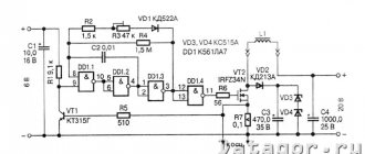
After the magnetic field is saturated, the coil resistance stops increasing. Previously, saturation coils formed the basis of voltage stabilizers. Today they have been replaced by electronic systems.
Antialiasing filters
What is a throttle in electronics? These are smoothing filters that straighten the AC voltage ripple line. As a result, the stability of the electronic equipment is ensured. This filter looks like a barrel on a USB cable. Inside it is a single-turn coil. Electronic boards use chokes of the r68 brand.
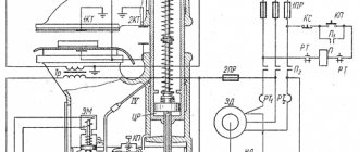
Magnetic amplifiers (MU)
They were included in the electric motor control system. Magnetic induction in the core was saturated by magnetization of the core steel. The starter used several windings at once. Today, instead of magnetic starters, thyristor systems are used.
Magnetic starter circuit
Resonant circuits
A resonant circuit is used in tuners. An inductive coil in parallel with a capacitor is combined into a single system, which constitutes a resonant circuit. The circuit provides low resistance with a fixed frequency.
Electronic choke in radio, - and computer circuits
Inductors of the r68 type are used in circuit boards to isolate currents of a certain frequency. They also play the role of protection from both external and internal interference of parts of the circuit.
Connection diagram
Chokes are often found in power supplies and fluorescent lamps. Connection to the inductor circuit for such options will be presented below in the article.
Fluorescent lamp
In such a circuit, the inductor acts as a starting and smoothing device. It is connected in series with the lamp. In this case, a starter is also used in conjunction with it. With this connection, the inductor uses the following operating principle:
- Alternating current flows through the circuit.
- A fluorescent lamp does not turn on when cold due to its high resistance. The flowing current does not start the lamp, but heats its cathodes, and then flows to the starter.
- The moving contact heats up inside the starter. After heating, the contact closes the circuit.
During the heating of the cathodes and the starter, current accumulates in the inductor circuit. When the starter closes, the current is displaced by the choke and the starter itself is discharged. During discharge, electrons at the cathodes of the lamp begin to move. They come into contact with the gas, and the lamp lights up. The diagram of a fluorescent lamp, consisting of a choke, two starters and two fluorescent lamps, is presented below.
power unit
Beginner radio amateurs often have this question: why do you need a choke in the power supply? It is necessary for two reasons:
- To smooth out the alternating current component.
- To smooth out pulsations.
As a rule, the chokes in these blocks are installed after the diode bridge directly at the output, which means they already work with direct current. When the voltage increases or there is a short circuit, the inductor smoothes out a significant part of the ripple. With stable operation of the power supply, the device smoothes out high-frequency interference by passing only direct current into the circuit without any fluctuations. Such a damper also acts as an additional resistance, which significantly reduces the voltage at the bridge output. The choke and such a connection diagram are shown in the figure below.
Main characteristics
The main characteristics include the following indicators:
- induction value;
- loss of resistance;
- core loss;
- losses due to eddy currents;
- parasitic capacitance;
- TCI (temperature coefficient of inductance).
Additional Information . The characteristics of inductors are needed to calculate new device models. Parameters are also used in PCB design.
Parallel oscillatory circuit.
If you connect an inductor and a capacitor, you get a very interesting element of radio engineering - an oscillatory circuit. If you charge a capacitor or induce E.M.F. in the coil using an electromagnetic field, the following processes will begin to occur in the circuit: The capacitor, when discharged, excites an electromagnetic field in the inductor. When the charge is depleted, the inductor returns the stored energy back to the capacitor, but with the opposite sign, due to the E.M.F. self-induction. This will be repeated again and again - electromagnetic oscillations of a sinusoidal shape will appear in the circuit. The frequency of these oscillations is called the resonant frequency of the circuit, and depends on the values of the capacitor capacitance (C) and the inductance of the coil (L).
A parallel oscillatory circuit has a very high resistance at its resonant frequency. This allows it to be used for frequency selection (selection) in the input circuits of radio equipment and intermediate frequency amplifiers, as well as in various master oscillator circuits.
Marking of small devices
Devices for electronic boards have dimensions of no more than 2-3 cm. It is almost impossible to apply readable markings in digital or letter designations. For this purpose, color coding of electronic chokes is used. Chokes in the diagrams are depicted in the form of a spiral with a parallel line.
Several colored rings are applied to the cylindrical body of the radio component. The first two bars (from left to right) indicate the inductance value, measured in mHenry. The third bar indicates the multiplier by which the inductance number should be multiplied. The fourth ring expresses the permissible deviation in % from the nominal value. If it is not on the body of the part, then the tolerance is considered to be within 20%.
Color coding table
For example, the colors of the rings are in the following order: brown, yellow, orange and silver. This means an inductance value of 14 mH, where the deviation tolerance is 10%.
Technological progress does not stand still. Every year new analogues of outdated models appear. The development of new technologies in all areas of human activity requires the improvement of radio components, including chokes.
Examination
Before this, we found out what a choke is for, what this device consists of, where it is used and on what principle it works. Now let's try to find out how to test this element for functionality. Using a multimeter, you can always check the integrity of the element and the value of its inductance.
Inductance
To measure inductance, you will need a tester with a mode for measuring this parameter. Such capabilities of the multimeter are indicated by the letters “N” or “Gn”. This parameter is measured as follows:
- You need to set the multimeter to inductance measurement mode.
- Next, you will need to make sure that the device being tested is disconnected from electricity.
- Connect the measuring probes to the contacts of the element.
The device should show an inductance value close to those indicated on the device body.
Resistance
Measuring the resistance will help you find out the condition of the coil. The check in this case looks like this:
- The choke must be disconnected from the circuit.
- Switch the tester to resistance measurement mode.
- Connect the measuring probes to the contacts of the device.
An infinitely large resistance will indicate a break in the internal winding. If there is no resistance at all, this indicates a short circuit. The resistance value should be close to the characteristics indicated on the device body.
You can make sure that there is no short circuit by switching the tester to the “continuity” mode. The tester beeps to indicate the presence of a short circuit.
The design of the throttle and its purpose using the example of a railway track
AC track circuits are installed on some sections of railways. In these (electrified) sections, the contact wire is the direct conductor of current to electric locomotives, and the return lines are the rail threads and the ground.
In the case when current is passed through both rail threads, the AC rail circuit being installed is called a two-thread one. In this case, the purpose of the inductor transformer is to pass the reverse traction current bypassing the insulating joints on each side. Each device has two windings: main and additional.
While the train is moving, current flows through both halves of the inductor transformer winding, then the currents collide at the midpoint and branch out again in the direction of the traction substation. Correct installation of devices ensures that traction current does not influence the equipment.
Electronic analogues
The bulk of chokes are fairly large devices. To reduce their size, but not change the parameters, it is necessary to replace the inductor with a semiconductor stabilizer, which, in principle, is a high-power transistor. That is, the end result is an electronic throttle.
In fact, the installed transistor stabilizes voltage surges (fluctuations) and reduces its ripple. But you have to take into account the fact that the electronic choke is still a semiconductor device. So there is no point in using it in high-frequency devices.
Calculation method
DT is calculated using the method of fuzzy logic, neural networks, La Grange resolvent and others. Special programs have been developed that calculate device parameters in a matter of minutes. Main stages of calculation:
- entering the required data for calculation;
- the program outputs magnetization curve values and corrects errors;
- calculation by the system of geometric parameters of the core model.
By using a special formula, you can calculate the air gap in the device on your own. It looks like this: L*I²/V. the inductance of the inductor winding is L, and the direct current on the winding is I. The letter V denotes the volume of the iron core.