How to make a battery at home
Our first experiment is a simple homemade battery. First, let's decide what materials we will make the electrodes from. The efficiency of our current source will depend on the correct composition.
What elements can electrodes be made from?
Almost all metals are suitable for making electrodes; the main thing is to choose a pair, since each metal has its own electrode potential; examples are given in the table below.
Electrode potential of some metals
| Metal | Potential, µV |
| Chromium | +0.23 |
| Silver | +0.20 |
| Copper | +0.04 |
| Nickel | -0.13 |
| Tin | -0.25 |
| Cadmium | -0.58 |
| Iron | -0.52 |
| Aluminum | -0.53 |
| Zinc | -0.83 |
Expert opinion
Alexey Bartosh
Specialist in repair and maintenance of electrical equipment and industrial electronics.
Ask a Question
The table clearly shows that some metals have a negative electrode potential, while others have a positive one. So what materials are the batteries made from? The answer is simple - you need to choose materials such that the difference in their electrode potentials is maximum. The ideal solution is zinc (negative electrode) and chromium (positive electrode). With zinc it’s a little easier - you can try to find it. But chrome... Replace with silver? It will be a rather expensive item.
Let's focus on copper. Although it is much inferior to silver, it will not be difficult to find. We won’t look for zinc for the negative electrode either, but will take aluminum. So, the positive electrode will be copper, the negative electrode will be aluminum. Theoretically, our design requires a copper rod with a diameter of 8–10 mm and a length of 100–150 mm. But we will not look for it, but will limit ourselves to a copper winding wire with a diameter of 1–2 mm.
We take a piece of winding wire 1 m long, peel off the varnish insulation from it, fold it 10 times and twist it. We wrap our electrode in a porous cloth and wind aluminum wire over this structure. This will be the negative electrode. We use a 15% solution of table salt as an electrolyte. We pour the electrolyte into a suitable container and lower our element into it, having first soldered or screwed (aluminum is difficult to solder) wires to its electrodes.
Important! We do not lower the element completely - the current-carrying wires, if they are both copper, should not be in the electrolyte.
We connect a voltmeter to our battery. The display shows 0.8 V. Not bad. What current will such an element produce? We connect an ammeter to it and measure the short circuit current. 10 mA. Not enough, but we will assume that the experiment was more likely to succeed than not. In any case, a battery of several such elements will be able to power an LED. Well, let's go ahead and do the simplified Daniel-Jacobi element.
The voltage produced by the cell depends on the material of the electrodes and the type of electrolyte, and the current is proportional to their area. Let's increase the area of the electrodes, and take a solution of copper sulfate (copper sulfate) + a solution of table salt as the electrolyte, since our electrode is not zinc, but aluminum.
The electrodes will be larger, so we will use a liter jar. We take the same copper wire and roll it into a flat spiral. The diameter of the spiral is equal to the diameter of the bottom of the jar. We solder a copper mounting insulated (this is important) wire to the spiral. We roll a cylinder from a sheet of aluminum. The diameter of the cylinder is the diameter of the neck of the jar. Height - 40 mm less than the height of the can. We place a copper spiral on the bottom of the jar, install an aluminum cylinder on which we made “ears” in advance so that it hangs on the neck and does not fall to the bottom.
Pour 30 g of crystalline copper sulfate onto a copper spiral (you can find it at a hardware store). Prepare the electrolyte - dissolve 100 g of table salt in 1 liter of water. Carefully pour the electrolyte along the wall of the jar so that it is 10 mm below the top edge of the aluminum cylinder.
Now our element needs to be launched. When the copper sulfate dissolves slightly and a thin layer of blue liquid appears at the bottom of the container, close it for 10–20 seconds. element conclusions. The battery is ready for use. We measure the voltage - 0.9 V. Current - 80 mA. Better, but still not enough.
Expert opinion
Alexey Bartosh
Specialist in repair and maintenance of electrical equipment and industrial electronics.
Ask a Question
Important! Apparently, the current is small due to the fact that the electrolytes are not separated properly, and the copper sulfate electrolyte is generally full of table salt. And the copper electrode has a small area.
You will have to make a diaphragm that will prevent electrolytes from mixing, but will allow ions to pass through. Let's move on to option 3. Using a jar neck diameter of 5 mm, we make a copper cylinder, the height of which is 50 mm less than the height of the jar. We make two ears on the upper edge of the cylinder and bend them so that the cylinder hangs on the neck and does not fall into the jar.
Now an ion-permeable glass. Let's make it from ordinary thick cardboard (not corrugated). We roll up the cylinder with a diameter 2–3 mm smaller than the diameter of the copper cylinder and stitch it. The height of the cylinder is the height of the copper one. We sew the bottom to it.
We seal the seams of the glass in any convenient way - with waterproof glue, a heat gun, etc. We glue a ring of the same cardboard to the upper edge of the glass-membrane. It will prevent the membrane from failing and at the same time will serve as an insulator. We make two small holes in the cylinder from the very edge - one for the stirrer, the other for pouring water into the compartment with vitriol. We check our work for leaks - pour water and wait a few minutes. The walls of the glass should become damp, but without visible leaks.
Healthy! To check for leaks, it is better to use not water, but a salt electrolyte - 100 g of table salt per 1 liter of water.
We will make a stirrer from a thin plastic rod, bending it over a gas burner in the shape of a hockey stick. The aluminum electrode remains. Again, a cylinder of the same height with a diameter 1–2 mm less than the diameter of the glass. We also make and bend the ears. That seems to be all, you can start assembling the battery. We install the stirrer and copper electrode. Pour 100 g of crystalline copper sulfate into the bottom of the jar. We place an ion-permeable membrane-glass on top, passing the stirrer handle through one of the holes in the ring. We lower the aluminum cylinder into it.
Expert opinion
Alexey Bartosh
Specialist in repair and maintenance of electrical equipment and industrial electronics.
Ask a Question
Healthy. If there is no sheet copper, then you can use a winding wire with stripped insulation, winding it directly onto the membrane glass. While winding, it is better to insert a mandrel of the appropriate diameter into the glass so as not to crush it.
Pour water into the hole of the ring. The level is 1 cm below the edge of the neck of the jar. In a glass - a salt solution (100 g of salt per 1 liter of water). We connect an ammeter to the battery terminals and use a stirrer, stirring the copper sulfate, until the short circuit current reaches 500–600 mA. That's all, turn off the ammeter and measure the voltage. As required - 0.9 V. A completely different matter. This element can already be used.
What characteristics does this battery have? The structure worked for a month and a half, delivering full load for 4 hours a day. After this, it had to be disassembled and recharged with vitriol and saline solution. When recharging, it does not hurt to inspect the aluminum electrode, since during operation not only copper sulfate is consumed, but also aluminum. It will also have to be changed periodically, although much less frequently. The approximate capacity of the 6-cell galvanic battery was 550 Wh, the output voltage was 5.4 V.
Important! When operating such a battery, it is necessary to monitor the discharge current. If it decreases, we use a stirrer.
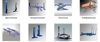
Acid and lead
The simplest design is the lead-acid design for storing electricity. To assemble it you need:
- stable container, with the possibility of tightly closing it with a lid;
- electrolyte – a solution of battery acid and distilled water;
- lead plate - you can use a flattened piece of lead from cable insulation or purchased at a hunting or fishing store;
- two metal pins - electrodes, which must be driven vertically into the lead plates.
Next, we present the manufacturing process of this device. Lead plates are placed on metal pins, with a small distance between them. After which the structure is immersed in a container filled with electrolyte. The lead must be completely under the solution. The contact ends of the pins are passed through the lid of the container and securely fixed to it. An electricity consumer can be connected to the ends of the electrodes. The container is placed on a stable surface, after which the device is charged. By complicating the design, rolling the lead plates into a roll and, accordingly, increasing their area, with a small volume, you can achieve good performance of such a device. The same principle is used to make rolls in modern gel energy storage devices.
Plates prepared for immersion in a jar
Important! When working with homemade electronic storage devices, follow safety rules: the acid used in the electrolyte is a rather aggressive substance.
Making a battery
Now let’s solve the question of how to make a battery with your own hands at home. More precisely, not yet a battery, but a single battery. Let's start with the most interesting design in terms of operating principles - a gas battery. To assemble such a current source, we will need:
- two carbon rods;
- Activated carbon;
- opaque container;
- cotton fabric;
- needle and thread;
- salt.
Carbon rods can be obtained from salt batteries, and those that have expired will also be suitable. Activated carbon is sold in pharmacies in tablets. A plastic cup painted or covered with opaque paper is suitable as an opaque container.
Unlike galvanic cells, both electrodes in gas batteries are made of the same materials and have the same design. But let's get down to business. Let's start with the extraction of electrodes. It is better to take D-size salt batteries - they have larger cores. It will not be difficult to get graphite out of them. We flare the upper side of the upper part of the battery, pry up the metal cover with an awl and remove it. There is a plastic gasket under the cover. We remove it with an awl too.
We see a graphite rod stuck into a black dense mass. We pick out the mass with an awl and remove the rod.
Now we take two mined graphite rods, attach wires to their ends in one way or another - these will be current leads. We sew two bags from cotton fabric of such a size that they contain approximately 80–100 grams of powdered activated carbon.
It's coal's turn. It is sold in tablet form, but we need it in powder. We crush the tablets in a mortar and mortar for a long time until we get very fine dust. We pour it into bags, insert coal rods, tamp it down, add more if necessary. We sew up our bags as carefully as possible and wrap them tightly with thread. The better we wrap it, the better the contact between the coal and the graphite rod will be.
We install the electrodes in a cup and separate them with some kind of separator. In the photo below, ordinary wood chips are used as a separator, but it is better to make something more ion-permeable. For example, thick batting.
The electrodes are in place, the electrolyte is ready
Fill in the electrolyte (100 g of salt per 1 liter of water), but not to the top - the contacts should remain dry. The battery is ready, but it still needs to be charged. Since we have the same electrodes, we arbitrarily choose which one will be positive and which negative. You can start charging. To do this, you will need a DC source with a voltage of 4.5–5 V. For example, a charger from any five-volt gadget will do. We connect it to the terminals and start charging.
Healthy! Before charging, it is better to wait 10–15 minutes so that the coal in the bags is properly saturated.
During the charging process, electrolysis of the electrolyte (sodium chloride + water) begins. As a result of electrolysis, hydrogen accumulates on one of the electrodes, and chlorine on the other. It is stored in the pores of activated carbon in its pure form and does not interact with anything. As soon as the “containers” are filled, a violent release of gases will begin (the battery will “boil”, since hydrogen and chlorine have nowhere else to accumulate). By that time, the voltage at the battery terminals will be 2.2–2.4 V.
With these dimensions, our rechargeable battery will have a capacity of approximately 1 Ah, and the short circuit current will be approximately 300 mA. As the discharge progresses, the voltage will decrease until it drops to zero - the device is not afraid of a complete discharge. And if desired, you can even reverse the polarity by charging it the other way around. While we discharge the battery, gases will leave the electrodes, reducing salt and water. What are the disadvantages of gas batteries? The main one is high self-discharge. Even if the load is completely turned off, the electrodes will lose gas, and literally after a couple of days the source will have to be charged again.
Expert opinion
Alexey Bartosh
Specialist in repair and maintenance of electrical equipment and industrial electronics.
Ask a Question
Important! To reduce self-discharge, it is necessary to completely protect the electrodes from light - take an opaque body and make a light-proof cover.
Now about lead batteries. Of course, good performance can be achieved from a battery of this type (as well as from an alkaline one). But the process of manufacturing a high-capacity lead battery is so expensive and labor-intensive that it makes no sense to manufacture a current source of this type. Therefore, we will not bother with making a lead-acid battery, but will simply watch an entertaining video. And if there is a desire, everyone can repeat this experiment on their own.
Homemade lead-copper battery
Everything seems simple, but, as we see, the results are disappointing. But there is no point in casting the plates yourself, applying lead oxide and dioxide on them, as noted above.
High-quality Li-ion 18650 charging systems
Lithium-ion electricity sources of this type are widely used with various devices. For their long-term operation, constant recharging is required. When charging, the voltage on the element reaches 4.2 V, after which it decreases to 2-3 V. With deep discharges (below 3 V), the service life of Li-ion 18650 is significantly reduced.
Important! Durability is affected by the number of charge-discharge cycles. This is the optimal number of cycles in which the battery capacity at the first charge (nominal) differs from the current capacity after charging by no more than 20%. The normal indicator is 350-500 charge-discharge cycles.
There are special chargers for such batteries, but you can make them yourself using a circuit.
The current is adjusted by selecting resistor R4 to the initial value of the charging current. It depends on the battery capacity. For example, if the battery capacity is 3000 mAh, then the charging current is 2-3 A.
Factory charge control systems independently adjust this parameter throughout the entire charging time.
Schemes for connecting batteries to a battery
We experimented with batteries and galvanic cells. Now let's move on to batteries, because most often the voltage of one element - be it a galvanic cell or a battery - is not enough to solve our problems. First of all, let's figure out in what ways you can connect individual elements and what this will give. For clarity, we will work with popular and very efficient industrial 18650 batteries.
This current source has the following characteristics:
- type - lithium-ion;
- output voltage - 4.2–2.8 V (depending on the degree of rarefaction);
- electrical capacity - from 1,800 mAh to 3,500 mAh, depending on the model;
- dimensions (height/diameter, mm) - 66.8/18.5;
- built-in controller (see section below) - depends on the model.
Suppose we have 3 batteries with a capacity of 2,200 mAh each and 1 with a capacity of 1,800 mAh. First, let's connect them in series:
When current sources are connected in series, their voltage is added, and the electrical capacity will be equal to the capacity of the lowest-power battery in the circuit. Thus, we received a battery with an output voltage of 3.7 x 4 = 14.8 V and a capacity of 1,800 mAh.
Important! Voltage 14.8 V is typical. Depending on the state of charge, this voltage can range from 16.8 to 11.2 V. Typically, a 4-cell assembly is considered a 12 V battery.
Now let’s connect our batteries in parallel:
When connecting elements in parallel, the voltage does not change, but the electrical capacitance is added. This means that our battery will still produce the same 3.7 V, but its capacity will be 2,200 x 3 +1,800 = 8,400 mAh. More than 8 Ah!
Safety precautions
Assembling a battery for an electric bicycle yourself is a feasible task, but when doing it, you must follow safety rules. The batteries and the battery assembled from them must be protected from falls, heating, deformation, damage, overcharging, short circuit, deep discharge and reverse polarity.
If significant heating is observed during battery assembly or testing, the process must be stopped. When using a soldering iron, the impact on the cells should be short-term - up to 2 seconds, to eliminate the risk of overheating. The soldering iron must have a power of at least 80 W and thermal stabilization. The solder must be fusible.
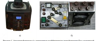
Simple automatic charger
For those who don’t have time to “bother” with all the nuances of charging a car battery, monitoring the charging current, turning it off in time so as not to overcharge, etc., we can recommend a simple car battery charging scheme with automatic shutdown when the battery is fully charged. This circuit uses one low-power transistor to determine the voltage on the battery.
Scheme of a simple automatic car battery charger
List of required parts:
- R1 = 4.7 kOhm;
- P1 = 10K trimmer;
- T1 = BC547B, KT815, KT817;
- Relay = 12V, 400 Ohm, (can be automotive, for example: 90.3747);
- TR1 = secondary winding voltage 13.5-14.5 V, current 1/10 of the battery capacity (for example: battery 60A/h - current 6A);
- Diode bridge D1-D4 = for a current equal to the rated current of the transformer = at least 6A (for example D242, KD213, KD2997, KD2999...), installed on the radiator;
- Diodes D1 (in parallel with the relay), D5.6 = 1N4007, KD105, KD522...;
- C1 = 100uF/25V.
- R2, R3 - 3 kOhm
- HL1 - AL307G
- HL2 - AL307B
The circuit lacks a charging indicator, current control (ammeter) and charging current limitation. If desired, you can put an ammeter at the output at the break of any of the wires. LEDs (HL1 and HL2) with limiting resistances (R2 and R3 - 1 kOhm) or light bulbs in parallel with C1 “mains”, and to the free contact RL1 “end of charge”.
Changed scheme
A current equal to 1/10 of the battery capacity is selected by the number of turns of the secondary winding of the transformer. When winding the transformer secondary, it is necessary to make several taps to select the optimal charging current option.
The charge of a car (12-volt) battery is considered complete when the voltage at its terminals reaches 14.4 volts.
The shutdown threshold (14.4 volts) is set by trimming resistor P1 when the battery is connected and fully charged.
When charging a discharged battery, the voltage on it will be about 13V; during charging, the current will drop and the voltage will increase. When the voltage on the battery reaches 14.4 volts, transistor T1 turns off relay RL1, the charging circuit will be broken and the battery will be disconnected from the charging voltage from diodes D1-4.
When the voltage drops to 11.4 volts, charging resumes again; this hysteresis is provided by diodes D5-6 in the emitter of the transistor. The circuit's response threshold becomes 10 + 1.4 = 11.4 volts, which can be considered to automatically restart the charging process.
This homemade simple automatic car charger will help you control the charging process, not track the end of charging and not overcharge your battery!
Website materials used: homemade-circuits.com