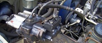
A transformer that has an electrical connection between the windings is called a laboratory autotransformer, or LATR. The load circuit voltage is directly proportional to the secondary circuit winding. Depending on the design, obtaining the desired output voltage is done by connecting to the appropriate terminals or rotating a manual regulator (Fig. 1). This article describes how to make LATR at home.
Preparation of material
To assemble the LATR you will need the following materials and devices:
- Copper winding;
- Toroidal or rod magnetic circuit. Can be purchased at a specialized store or removed from damaged equipment;
- Heat-resistant varnish;
- Rag tape;
- Housing with fixed connectors for connecting load and power.
For a laboratory LATR with a variable transformation ratio, you may additionally need:
- Digital or analog voltmeter.
- Rotary mechanism, including a handle and a slider with a carbon brush. It will regulate the voltage.
Advantages and disadvantages
To the advantages described above, we can add the low cost of products, due to the reduction in the cost of non-ferrous metals used and the cost of transformer steel. Autotransformers are characterized by insignificant energy losses of currents circulating through the windings and cores, which makes it possible to achieve efficiency levels of up to 99%.
To the disadvantages should be added the need for solid neutral grounding equipment. Due to the existing probability of a short circuit and the possibility of transmitting high voltage through the network, there are certain restrictions on the use of autotransformers.
Due to the galvanic connection of the windings, there is a danger of atmospheric overvoltages passing between them. However, despite their disadvantages, autotransformers still find wide application in a wide variety of fields.
Wire calculation
It is not advisable to use an autotransformer for large transformations for the following reasons:
- There is a high risk of receiving currents close to a short circuit. This is compensated by special electronic circuits or additional resistance. For small loads it is more profitable to use an electronic LATR.
- The advantages over transformers are lost: high efficiency, saving on conductor and steel, small dimensions and weight, cost.
We are determining within what limits the LATR will operate. We select 220 V for the network supply. We select 127, 180 and 250 V as secondary voltages. We limit the power to 300 W. You can choose your own values and make similar calculations using the example of this article.
The winding is calculated based on the larger current. The highest current will be when converting a voltage of 220 to 127 V. The autotransformer in this case is a step-down one, and circuit 1 is suitable for it. Based on the provided circuit, we calculate the maximum current I passing in the winding of both circuits:
I = I2 – I1 = P / U2 – P / U1 = 300 / 127 – 300 / 220 = 1 A
- where I, I2, I3 are currents in the corresponding sections of the circuit, A;
- P – power, W;
- U1, U2 – primary and secondary circuit voltages, V.
The wire diameter is calculated using the formula:
d = 0.8 * √I = 1 mm.
From Table 1, select the wire type and cross-section. We make the choice taking into account the calculated current and the average current density for transformers - 2 A/mm².
The LATR transformation coefficient n is calculated using the formula:
n = U1 / U2 = 220 / 127 = 1.73
For further calculation, we calculate the design power Pр:
Pр = P * k * (1 – 1/n) = 300 * 1.2 * (1 – 1/1.73) = 151.92 W
where k is a coefficient that takes into account the efficiency of the autotransformer.
To determine the number of turns per 1 volt, it is necessary to calculate the cross-sectional area of the core S and determine the type of magnetic circuit:
S = √ Pр = √ 151.92 = 12.325 cm²
W0 = m / S = 35 / 12.325 = 2.839
- where W0 is the number of turns per 1 volt;
- m – 50 for rod and 35 for toroidal magnetic cores.
If the steel is not of very high quality, it is worth increasing the W0 value by 20-30%. Also, when calculating turns, their number should be increased by 5-10% to avoid voltage sag. We calculate the number of turns for selected voltages 127, 180, 220 and 250 V:
w = W0 * U
We get 360, 511, 624 and 710 turns.
To calculate the length of the wire, we wrap one turn around the magnetic circuit and measure its length. Then we multiply by the maximum number of turns and add 25-30 centimeters for each terminal to the terminal.
About the principle of operation of devices
An adjustable laboratory autotransformer, abbreviated LATR, is a device based on a magnetic core with a copper winding, where an electrical connection occurs. A carbon brush moves along the winding, thereby creating contact with the connected electrical consumer. Depending on the position of the brush, the transformation ratio changes, which, in turn, affects the value of the output voltage. Thanks to the rotary regulator, which changes the position of the brush, you can adjust the value of the current voltage supplied to the load on a scale.
Electrical consumers are connected to the laboratory autotransformer through the output terminals, in turn, the device itself is connected to the central electrical network either through the input terminals or by connecting the electrical plug to the socket.
The main difference between laboratory autotransformers and conventional ones is that the movable contact in the winding allows you to change the number of turns connected to the circuit and thereby makes it possible to set the voltage in a wide range, for example, in a single-phase network - from 0 to 250 V, in a three-phase network - from 0 up to 430 V. The number of turns changes smoothly, so it is possible to obtain the most accurate voltage values and a pure sine wave at the output. In addition, this device is lighter and more compact than analogues made according to the traditional design, and has a much higher efficiency (up to 98%). To monitor operation, there is a voltmeter on the control panel, and ventilation grilles in the case promote natural cooling of the device and prevent overheating.
Examination
To ensure the smooth and reliable operation of the device, we perform the following points:
- We connect the autotransformer to a 220 V network;
- We check for the absence of smoke, burning smell, strong noise;
- We use a voltmeter to check the compliance of the output values;
- After 10 - 20 minutes of operation, turn off the LATR. Check to see if the winding is overheated.
- We turn the LATR back into the network and connect the load for a long time.
If there are no problems, the autotransformer is ready for operation.
A transformer that has an electrical connection between the windings is called a laboratory autotransformer, or LATR. The load circuit voltage is directly proportional to the secondary circuit winding. Depending on the design, obtaining the desired output voltage is done by connecting to the appropriate terminals or rotating a manual regulator (Fig. 1). This article describes how to make LATR at home.
Safety precautions when working with LATR
I would also like to add a few words about safety precautions. There are LATRs without galvanic isolation . This means that the phase wire from the network goes directly to the output of such a LATR. The LATR circuit without galvanic isolation looks like this:
In this case, a network voltage of 220 Volts may appear at the output terminal of the LATR with a probability of 50/50. It all depends on how you plug the LATR mains plug into a 220 Volt socket.
If you look closely at the circuit diagram on the front panel of the LATR Resanta, you can see that the “X” and “x” terminals (the two bottom ones) are connected to each other by a conductor.
That is, if there is a phase on the “X” terminal, then there will also be a phase on the “x” terminal! You won’t measure the phase in the socket every time to insert the plug correctly, will you? Therefore, BE extremely CAREFUL! Try not to touch the LATR output terminals with your bare hands!
In principle, I touched it and nothing like that happened to me. The problem turned out to be that I have a wooden floor, which is almost a dielectric. I measured the voltage between me and the phase - about 40 Volts came out. That's why I didn't feel these 40 Volts. If I grabbed the battery with one hand or stood with my bare feet on the ground, and with the other hand grabbed the output “x” of the LATR, then I would be shaken very, very hard, since all the full 220 Volts would pass through me.
Preparation of material
To assemble the LATR you will need the following materials and devices:
- Copper winding;
- Toroidal or rod magnetic circuit. Can be purchased at a specialized store or removed from damaged equipment;
- Heat-resistant varnish;
- Rag tape;
- Housing with fixed connectors for connecting load and power.
For a laboratory LATR with a variable transformation ratio, you may additionally need:
- Digital or analog voltmeter.
- Rotary mechanism, including a handle and a slider with a carbon brush. It will regulate the voltage.
Application area
The features of the autotransformer allow it to be used in everyday life and various areas of industry.
Metallurgical production
Regulated autotransformers in metallurgy are used to check and adjust the protective equipment of rolling mills and transformer substations.
Utilities
Before the advent of automatic stabilizers, these devices were used to ensure the normal operation of televisions and other equipment. They consisted of a winding with a large number of taps and a switch. He switched the output of the coil, and the output voltage was controlled using a voltmeter.
Currently, autotransformers are used in relay voltage stabilizers.
Reference! In three-phase stabilizers, three single-phase autotransformers are installed, and adjustment is made in each phase separately.
Chemical and petroleum industry
In the chemical and petroleum industries, these devices are used to stabilize and regulate chemical reactions.
Production of equipment
In mechanical engineering, such devices are used to start electric motors of machine tools and control the rotation speed of additional drives.
Educational establishments
In schools, technical schools and institutes, LATRs are used to perform laboratory work and demonstrate the laws of electrical engineering, and experiments on electrolysis.
Wire calculation
It is not advisable to use an autotransformer for large transformations for the following reasons:
- There is a high risk of receiving currents close to a short circuit. This is compensated by special electronic circuits or additional resistance. For small loads it is more profitable to use an electronic LATR.
- The advantages over transformers are lost: high efficiency, saving on conductor and steel, small dimensions and weight, cost.
We are determining within what limits the LATR will operate. We select 220 V for the network supply. We select 127, 180 and 250 V as secondary voltages. We limit the power to 300 W. You can choose your own values and make similar calculations using the example of this article.
The winding is calculated based on the larger current. The highest current will be when converting a voltage of 220 to 127 V. The autotransformer in this case is a step-down one, and circuit 1 is suitable for it. Based on the provided circuit, we calculate the maximum current I passing in the winding of both circuits:
I = I2 – I1 = P / U2 – P / U1 = 300 / 127 – 300 / 220 = 1 A
- where I, I2, I3 are currents in the corresponding sections of the circuit, A;
- P – power, W;
- U1, U2 – primary and secondary circuit voltages, V.
The wire diameter is calculated using the formula:
d = 0.8 * √I = 1 mm.
From Table 1, select the wire type and cross-section. We make the choice taking into account the calculated current and the average current density for transformers - 2 A/mm².
The LATR transformation coefficient n is calculated using the formula:
n = U1 / U2 = 220 / 127 = 1.73
For further calculation, we calculate the design power Pр:
What is an autotransformer?
From a school physics course we know that the simplest transformer consists of two coils wound on iron cores.
The magnetic field of alternating current, powered through the terminals of the primary windings, excites electromagnetic oscillations in the second coil, with a similar frequency. When a load is connected to the terminals of the working winding, it forms a secondary circuit in which an electric current arises. In this case, the voltage in the formed electrical circuit is directly proportional to the number of turns of the windings. That is: U1/U2 = w1/w2, where U1, U2 are voltages, and w1, w2 are the number of full turns in the corresponding coils.
Figure 1. Diagram of a conventional transformer and autotransformer
The autotransformer is designed a little differently. It essentially consists of one winding, from which one or more taps are made, forming secondary turns. In this case, all windings form not only an electrical, but also a magnetic connection with each other. Therefore, when electrical energy is supplied to the input of the autotransformer, a magnetic flux arises, under the influence of which an emf is induced in the load winding. The magnitude of the electromotive force is directly proportional to the number of turns forming the load winding from which the voltage is removed.
Thus, the formula given above is also valid for an autotransformer.
A large number of leads can be drawn from the main winding, which allows you to create combinations for removing voltages of different magnitudes. This is very convenient in practice, since voltage reduction is often required to power several units of electrical appliances using different voltages.
The difference between an autotransformer and a conventional transformer
As can be seen from the description of the autotransformer, its main difference from a conventional transformer is the absence of a second coil with a core. The role of secondary windings is performed by separate groups of turns having a galvanic connection. These groups do not require separate electrical insulation.
This device has certain advantages:
- the consumption of non-ferrous metals used for the manufacture of such equipment has been reduced;
- energy transfer is carried out by the influence of the electromagnetic field of the input current, and thanks to the electrical connection between the windings. Consequently, energy loss is lower, which is why autotransformers have higher efficiencies;
- light weight and compact dimensions.
Despite the design differences, the operating principle of these two types of products remains unchanged. The choice of transformer type depends, first of all, on the goals and tasks that have to be solved in electrical engineering.
Types of autotransformers
Depending on which networks (single-phase or three-phase) the voltage needs to be changed, the appropriate type of autotransformer is used. They are single-phase or three-phase. To transform current from three phases, you can install three autotransformers designed for operation in single-phase networks, connecting their terminals with a triangle or an asterisk.
Transformer winding connection diagram
There are types of laboratory autotransformers that allow you to smoothly change the output voltage values. This effect is achieved by moving a slider along the surface of the open part of a single-layer winding, similar to the operating principle of a rheostat. Turns of wire are applied around a ring-shaped ferromagnetic core, along the circumference of which the contact slider moves.
Autotransformers of this type were widely used throughout the USSR during the era of mass distribution of tube televisions. At that time, the network voltage was unstable, which caused image distortion. Users of this imperfect technology had to adjust the voltage to 220 V from time to time.
Before the advent of voltage stabilizers, the only way to achieve optimal power parameters for household appliances of that time was the use of LATR. This type of autotransformer is still used today in various laboratories and educational institutions. With their help, electrical equipment is adjusted, highly sensitive equipment is tested, and other tasks are performed.
In special equipment where the loads are insignificant, DATR autotransformer models are used.
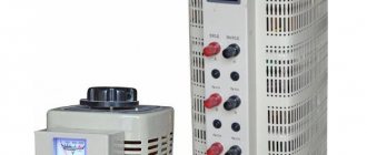
Autotransformer LATR
There are also autotransformers:
- low power, for operation in circuits up to 1 kV;
- medium-power units (more than 1 kV);
- high-voltage autotransformers.
It should be noted that for safety reasons, the use of autotransformers as power transformers to reduce voltages exceeding 6 kV to 380 V is limited. This is due to the presence of a galvanic connection between the windings, which is not safe for the end user. In case of accidents, it is possible that high voltage will reach the powered equipment, which is fraught with unpredictable consequences. This is the main disadvantage of autotransformers.
Designation on diagrams
It is very easy to distinguish the autotransformer in the diagram from the image of a conventional transformer. A sign is the presence of a single winding connected to one core, indicated by a thick line in the diagrams. Windings are shown schematically on one or both sides of this line, but in an autotransformer they are all connected to each other. If the turns are shown autonomously in the diagram, then we are talking about a regular transformer.
Build process
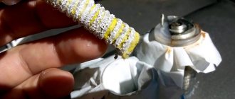
To assemble an adjustable LATR, we select a toroidal magnetic core (Fig. 2). We insulate the place where the winding is applied with rag tape. We bring out the wire for the first power terminal. We bring out all subsequent wires without breaking them. We fix the first turn on the magnetic core and begin to wind the calculated amount. When a turn corresponding to one of the selected voltages is reached, we remove the loop and continue winding the wire. Figure 3 shows the winding process on a wooden frame.
After applying the winding, we varnish LATR. We fill the container with the selected varnish and dip the autotransformer into it. Leave to dry for a long time.
After drying, place the autotransformer in the housing. We connect the first output wire to the power connector. This connector must be electrically connected to the common load terminal, so we connect them together with some kind of conductor. We connect the loop output for 220 V to the second power terminal. We connect the remaining wires to the corresponding terminals of the secondary circuit. “Scheme” 2 shows the wire terminals.
For a laboratory autotransformer with a variable transformation ratio, we add a housing and make a mount for the regulator handle. We attach a slider with a carbon brush to the handle. The brush should touch the top of the winding tightly. We mark the area over which the brush will move, and in this place we get rid of the insulation. This way the brush will have direct electrical contact with the secondary winding. We replace the secondary voltage terminals, in addition to the common one, with one connected to a carbon brush (diagram 3). When connecting, secure the voltmeter.
If you follow the written article, you can easily make LATR with your own hands.
Where are they used?
The main areas of application of the devices are:
- Compensation for potential drop in distribution systems, which is produced by increasing supply voltage values.
- Control systems for asynchronous and synchronous motors, where the presence of an autotransformer with several taps makes starting easier.
- In research laboratories, when it is necessary to vary electrical variables within wide limits.
These devices are also used to adjust the brightness of light; Such devices are called dimmers. In these cases, special attention is paid to the correct selection of fuses, otherwise a higher supply voltage may end up at the secondary terminals.
Examination
To ensure the smooth and reliable operation of the device, we perform the following points:
- We connect the autotransformer to a 220 V network;
- We check for the absence of smoke, burning smell, strong noise;
- We use a voltmeter to check the compliance of the output values;
- After 10 - 20 minutes of operation, turn off the LATR. Check to see if the winding is overheated.
- We turn the LATR back into the network and connect the load for a long time.
If there are no problems, the autotransformer is ready for operation.
The main reason for creating an electronic LATR with your own hands is the abundance of unreliable regulators on the electrical goods market. A way out of the situation may be an industrial-type sample, but such specimens are expensive and have impressive dimensions, which makes it difficult to use at home.
Electronic LATR device diagram.
Important selection options
First of all, you need to determine what the autotransformer will be used for. For example, to test the performance of power equipment at a factory, you will need one model; to provide power supply when repairing car radios, you will need a completely different one. To make it easier to formulate requirements for the device, consider the following parameters:
Power. You can select an LATR with a power from 0.45 to 10 W (and even more), but first you need to calculate the load of all connected electrical consumers. Their total power should not exceed the power of the autotransformer.
Voltage adjustment range. It depends on how the device operates - to lower or increase voltage parameters. Most models are of the step-down type, especially single-phase; their operating range can be from 0 to 250 V or from 160 to 220 V. Depending on what voltage value is needed to operate the equipment, choose an LATR with the appropriate range. Three-phase models have a wider range: the lower limit can be at a level of 200-220 V. A laboratory autotransformer with a wide operating range is not always needed, for example, if the voltage in the network drops to 180 V (not higher or lower), then you can buy transformer with adjustment within 180-220 V.
Supply voltage. If you plan to connect the device to a single-phase network, then you need to buy a 220 V model, if to a three-phase network - 380 V (in this case, the adjustment range for such a model can go far beyond the nominal values of a three-phase network, for example, it can be from 0 to 430 IN).
So, have you already decided to buy a laboratory autotransformer? With this device, you yourself can adjust the voltage in the network and set the values that are necessary for a specific type of energy consumer. You can quickly select and order suitable equipment on our website. Don't delay your purchase - take control of your stress!
What is the device
It is worth mentioning that laboratory autotransformers (LATR) were widely used half a century ago. Previous versions of the device had a current-collecting contact, which was located on the secondary winding. This made it possible to smoothly change the output voltage (its value).
If all kinds of laboratory instruments were connected, there was an option to quickly change the voltage. For example, if necessary, it was easy to influence the degree of heating of the soldering iron, adjust the brightness of the lighting, the speed of the electric motor, and much more. This is a kind of regulating power supply.
Figure 1. Scheme of a simple version of LATR.
The current version of LATR has various modifications. In general, it can be considered a transformer in which an alternating voltage of one value is transformed into an alternating voltage of another. The device is widely used as a voltage stabilizer. The main feature is the ability to change the voltage at the output of the device. LATRs come in several versions:
Types of LATRs
Single-phase
This type of LATR produces single-phase alternating regulated voltage. It is very often used by radio amateurs, as it allows you to select any low-voltage alternating voltage.
Three-phase
This type of LATR is used in industrial electronics. A three-phase voltage is supplied to its input, and at the output we get the same three phases, but with a smaller amplitude. This LATR allows you to change the voltage amplitude of all three phases simultaneously . Roughly speaking, these are three single-phase LATRs, which are located in the same housing and which change the voltage equally.
A simple device for regulation
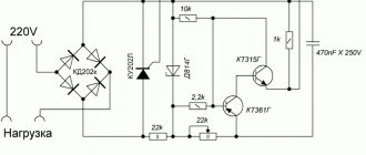
There is a very simple version of LATR, which is available even for beginners; its diagram is shown in Fig. 1. The voltage range regulated by such a device is within 0-220 volts. This homemade regulator has a power of 25-500 W. The power of the device can be increased by installing thyristors VD1 and VD2 on radiators.
Semiconductor devices (we are talking about thyristors VD1 and VD2) should be connected in parallel with the load R1. The current they pass has opposite directions. When the device is connected to the network, the thyristors remain closed, unlike capacitors C1 and C2, which are charged by resistor R5. If there is a need, using resistor R5 you can change the voltage that is obtained during load. The resistor and capacitors create a phase-shifting circuit.
Figure 2. LATR with a bipolar transistor.
A phase-shifting circuit is an electrical four-port network, the harmonic signal at the output of which is shifted in phase relative to the input signal. They are common in self-propelled guns as adjustment devices that provide stability and the necessary quality of control. Special cases are differentiating and integrating chains.
This technical solution allows you to use not half the power for the load, but full power. This is achieved due to the fact that both half-cycles of alternating current are used.
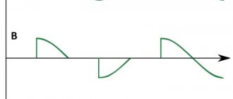
The disadvantages include the form of alternating voltage at the load. In this version it is not strictly sinusoidal. The specific operation of semiconductor devices is the main reason. The presence of such a feature can cause interference in the network. But they can be eliminated by additionally installing chokes (series load filters) on the circuit. Such filters can be found even in a faulty TV.
How LATR works in practice
Let's conduct experiments with a 95 Watt 220 Volt incandescent light bulb. To do this, connect it to the output terminals on the right.
I wonder at what voltage the light bulb filament will start to glow? Let's find out! We turn the regulator until we notice a faint glow of the light bulb.
We look at the regulator scale. 35 Volts!
Did you know that in the USA the mains voltage is 110 Volts? I wonder how our light bulb would glow then? We set it to 110 Volts.
It glows, as they say, at full incandescence.
Now compare how it glows at 220 V
There is no point in increasing the voltage further. The light bulb may burn out.
If you want to set the voltage with great accuracy, then, of course, you can’t do without a multimeter. To do this, set the multimeter knob to the AC voltage measuring position.
We cling and measure the alternating voltage. At the same time, we adjust it using the LATR regulator. Exactly 110 Volts!
Exploitation
Laboratory autotransformers are mostly used in laboratories and various research centers.
The main purpose is to test various AC equipment. Quite often, such units are used to ensure stabilization of the mains voltage. For example, in case of insufficient indicators at the current moment in the power grid.
The scope of operation of a laboratory transformer is very limited:
- in case of rare voltage drops in the electrical network, the device guarantees its stable, uninterrupted operation;
- in the presence of regular voltage drops or even surges, the use of a transformer does not provide any efficiency. In this case, it becomes necessary to additionally purchase a stabilizer.
The main purpose of a laboratory autotransformer is considered to be the ability to fine-tune voltage indicators to achieve the assigned tasks:
- conducting experiments;
- testing various equipment, etc.
The type of equipment under consideration may well be needed during commissioning of devices (with increased voltage sensitivity) in industry. It is often used by radio electronics, which with the help of the device makes it possible to provide proper power to equipment (for example, if it operates exclusively at low voltage) or to charge the battery.
Key Features
The definition of LATR means one of the types of autotransformers. A distinctive feature is considered to be:
- low power levels;
- there is no need for a state register.
The operating principle of a laboratory regulating autotransformer is to adjust the AC voltage of a single-phase or three-phase network.
Laboratory autotransformer circuit
The autotransformer circuit contains a toroidal steel core. It has only one contour:
- two separate windings are missing;
- the contours are combined. One part may well belong to the coils of the primary type, and the second to the secondary.
Help : the laboratory autotransformer has a very simple circuit that anyone can master. The user has the right to independently adjust the number of turns from the secondary winding.
This is precisely what distinguishes LATR from other types of transformers.