SCART, as a unified connector, was first introduced by a French company. It was created to optimize signals from devices from various manufacturers. Thanks to the creation of a single format, users had the opportunity to buy models of household appliances from different brands, thereby allowing them to make a choice in favor of comfort, convenience, reliability and practicality.
There are other types, but these are the most common. Practical example: Connecting a VCR. Most VCRs have a "modulator". Often they would "modulate" on channel 37, but this could usually be changed. Below is general information about equipment with modulators.
I have a box that doesn't have a modulator!
All is not lost - there are three options. So, what do we need to know about this type of communication and when should we use it? It is not compatible with modern digital signals. You may not use it right away, but it may be useful later. Adding one later is very difficult, if not impossible!
The introduction of the universal connector was carried out intensively, by banning, starting in 1981, the production of equipment with other types of connections. New format
was introduced as mandatory for all manufacturers without exception. But at the same time, SCART began to be actively used throughout Europe only 3 years later, becoming a standard regulated by EN 50049-1. Due to its format and design, the connector has received many common names, such as comb and ratchet.
They come in several varieties. Typically these cards come with special cables that convert the connector to a more generic connector, such as a tulip connector for composite video. Some cards have a tulip connector. This is typically a composite video signal in which the color and sync signals are mixed into 1 signal.
Antenna. Antenna connectors - these two. You will usually find it on the back of your equipment. The downside is that you will need to build or buy a separate cable. Note. Note: The core of the tulip connector is a signal. The silver ring around it protects.
Scart pinout - correct pinout
Scart pinout - in the early 80s, the French joint company of radio and television developers designed a multi-pin SCART connector.
Using this audio-video interface, it became possible to broadcast data received from RGB signal sources. This device, which provides excellent video quality, quickly became a fairly popular connector in Europe. Somewhat later, this 21-pin connector found its application in players and video recorders produced by famous world brands. There are currently many popular systems for exchanging information using SCART.
In terms of design, the connector was developed to perform switching of various types of data in digital and analog format. This includes the transmission of audio and video signals, with the help of just one such connector it has become possible to record and play video content. In addition, a command transmission function is available to control the multimedia device during its setup.
Design features and scart pinout
The pinout of the scart connector is made according to a 2-component asymmetrical circuit; double-row spring-loaded male contacts transmit signals (20 are signal paths and 1 for protection). The outer housing of the contact connector has a characteristic shape that serves as a kind of key. It is this structural protrusion that guarantees the correct connection of the SCART; if it is unfolded during connection, the connection will be impossible.
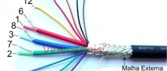
The pinout of the SCART connector is carried out by installing odd numbers of contact blades at the bottom of the connector, while the cable key will be on the right side. The upper row of contacts, which have even designation numbers, is made with some offset relative to the lower row. It is this arrangement of the “knives” that prevents the connector from being connected in the opposite direction. The order of signal data through the contacts is shown in the table below. The protective wire, placed in a braided shield, is connected to 21 contacts.
| Contact no. | Purpose | Signal level, circuit resistance |
| 1 | Right channel audio output (mono) | Veff. = 0.2-2.0V, R 10kOhm |
| 3 | left channel audio output | Veff. = 0.2-2.0V, R 10kOhm |
| 7 | “BLUE” signal input/output | swing 0.7 V VDC = 0-2.0 V, R=75 Ohm |
| 8 | TV/VIDEO switching voltage input/output | Voff = 0 - 2.0 V, Von. = 9.5 - 12V, Rinput. > 10kOhm, Rout. Making a SCART cable with your own hands |
The need to manufacture a connector with a SCART connector at home may be caused by the need to create a multimedia complex for the home. And the pinout of the scart connector is done according to the table presented. When making a SCART connector yourself, it is not necessary to use all the contacts; you can connect only the ones you need. The place where the wire is soldered to the contact should be placed in a casing, possibly with heat-shrinkable properties.
SCART, as a unified connector, was first introduced by a French company. It was created to optimize signals from devices from various manufacturers. Thanks to the creation of a single format, users had the opportunity to buy models of household appliances from different brands, thereby allowing them to make a choice in favor of comfort, convenience, reliability and practicality.
The introduction of the universal connector was carried out intensively, by banning, starting in 1981, the production of equipment with other types of connections. The new format was introduced as mandatory for all manufacturers without exception. But at the same time, SCART began to be actively used throughout Europe only 3 years later, becoming a standard regulated by EN 50049-1. Due to its format and design, the connector has received many common names, such as comb and ratchet.
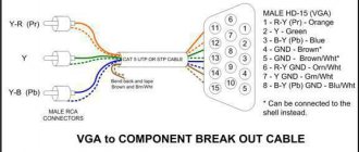
VGA-SCART pin assignments
To understand the functioning of the following VGA SCART adapter circuits, let's look at the different types of signals that need to be transmitted from the computer to the TV.
RGB signal
The main signal that is transmitted through the cable from the computer to the TV is an RGB signal divided into three components (R-red, G-green, B-blue). Fortunately, in this case, the standard VGA connector and the SCART connector are fully compatible (outputs: amplitude 0.7V, resistance 75 Ohm). Therefore, you can directly connect the corresponding contacts without resorting to the use of special circuits or devices (we will consider this option later).
Common wire
VGA and SCART connectors have several pins connected to a common wire (ground), which are often connected to each other inside the cable. Their common connection makes it possible to eliminate various interferences (especially in relation to the three RGB lines). The same applies to shielded cable.
Note: there is essentially only one common wire, so it is normal that all contacts marked with ground are connected together.
Signal Audio
In order to output sound to the TV, you need to take a cable with a standard 3.5 mm connector for a PC and connect it directly to the SCART connector. You can output both mono and stereo sound without resorting to the use of special devices and circuits. Just be careful not to confuse the audio output with the audio input, since SCART has them next to each other.
Switching signals
As mentioned earlier, the SCART input can accept different types of signals. In order for the TV to understand what type of signal is supplied to the input, there is a special “RGB Blanking” contact (pin 16). If a voltage of 0...0.4V is applied to this contact, then the TV will expect a “Composite signal”; if 1...3V, then the signal will be “RGB”. The use of this type of signal is extremely important for the functioning of the VGA-SCART adapter, and as we will see later, there are various ways to obtain it.
Another pin that might interest us is “Swtch” (pin 8). This pin is intended for switching TV/AV mode. Also on some TVs, this pin allows you to set the aspect ratio of the image:
- TV mode - from 0 to 2 V.
- AV mode with 16:9 ratio – 5 to 8V.
- AV mode with 4:3 ratio - 9.5 to 12V.
If we do not send a signal to this pin, the TV will remain in its default state (TV mode), and then to switch to AV mode we will need to use the remote control.
Synchronization signals
This is where the most difficult part about building a VGA-SCART adapter begins. The synchronization of signals on a computer's video card is very different from the synchronization system that is used in a regular TV, so you need to resort to some tricks to make them compatible. The difference between most VGA-SCART adapter circuits is based on ways to solve this problem.
In a computer, standard VGA uses two different signals for synchronization, one vertical (60 Hz) and one horizontal (31 kHz). Both signals operate according to TTL logic and hence have a peak value of 5V. Finally, the signals can be either positive or negative depending on the video operating mode used.
However, the TV only needs one composite sync signal with a peak value of about 1...3V. Also, the horizontal frequency is much lower, about 15 kHz (vertical, but 50...60 Hz is almost the same). Finally, the signal should always be negative.
The main problem we face is horizontal synchronization. Assembling a circuit for this transformation is quite a difficult task. In this case, as a rule, changes are made to the signal source itself (video card), using special software or even a modified VGA (like the famous ArcadeVGA) to directly obtain 15 kHz at the VGA output. We will consider this question further.
Pros and cons of TVs with a scart port
Connecting a computer to a TV via an RCA cable
The advantages of TVs with a scart port include:
- High quality color images.
- Great control possibilities.
- Clarity of pictures, since colors are transmitted separately, through the appropriate contacts.
- The connectors are coated with a special agent that helps eliminate interference.
- Using pinouts, it is possible to automatically turn on/off the television receiver and additional equipment simultaneously. For example, if you turn on a tape recorder or other device that is connected to the TV, they will start working together.
- Possibility to enable automatic widescreen image function.
The scart connector also has some disadvantages:
- With a very long cable, the signal is gradually lost until it reaches the desired point.
- To make the signal clearer, the braiding on the wire must be shielding. This means that the cable, in this case, will be too thick, and this is not entirely convenient.
- More recently, new DVI and HDMI interfaces for digital data transmission have entered the market, with a density much higher than that of a scart port.
- The scart connector cannot be used to connect some modern video entertainment centers, for example, such as Dolby Surround. To enjoy this privilege, more advanced special equipment is required.
- The quality of functioning of the scart connector depends directly on the type of television receiver. Plasma liquid crystal devices transmit high quality signals. But TVs equipped with a kinescope are too far from this and cannot boast of good data transmission, even modern models of this type.
- Not all types of video cards have the ability to support connections to scart ports. This paragraph applies exclusively to computers.
But, despite these disadvantages, scart connectors are still installed on many TVs.
How to use?
But even the negative aspects do not interfere with the popularity of such a standard. The fact is that the connection is quite simple - and this is what is primarily required for most TV owners. Let's say you need to connect a TV to a personal computer using a Euro SCART connector. Then one end of the cable is connected to where the video card is located.
If the procedure is performed correctly, the TV will automatically turn into an external computer monitor. You just need to wait until the pop-up window appears. It will notify the user about a new device found.
It will take some time to install the drivers. They may be placed incorrectly if:
- no signal;
- the video card is not configured correctly;
- outdated software versions are used;
- The horizontal sync signal is too weak.
In the first case, you must first turn off all devices that may be a source of interference. If this does not help, then the problem is related to the operation of the connector itself. Video card failure is usually resolved by manually updating drivers. But sometimes it turns out that it does not support SCART in hardware. And if the signal is too weak, you will definitely have to resolder the connector itself; a new setting at the software level is often necessary.
Contact distribution
USB pinout
The SCART connector is equipped with several groups of contacts that provide transmission of certain signals from the TV and back:
- 5 lines for transmitting and receiving audio;
- 9 lines for receiving and transmitting video signals;
- 2 lines for selecting modes;
- 3 lines for digital data transmission.
All lines are marked in different colors, which greatly facilitates the process of installation and connection of various devices. SCART is still very popular among a large number of users.
The scart implemented the ability to transmit stereo audio signals, which was later transferred to other more modern types of HDMI connectors. Due to the design features of the connector, data transfer is possible when controlled remotely. You can also connect unmodulated signals:
- composite;
- component;
- S-Video.
Component video signals include RGB and YPbPr. And S-Video includes 2 lines. The function of switching video signal reception modes and waking the TV from sleep mode upon command from an external device was added to the connector only in the late 80s. In the same years, SCART was supplemented with 2 video signal transmission lines S-Video.
Although the interface is large and inconvenient, many manufacturers still install it in their equipment with the expectation of using it to connect to old TV receivers. And in order to connect other types of devices to it, for example, a video camera, you will need a special adapter.
How to connect a computer to a TV via RCA?
| How to connect a computer to a TV via RCA? |
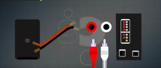
RCA is a special three-connector output on the external panel of modern TVs. The RCA output contains three colored connectors - white (black), yellow and red. All modern TVs and almost all modern video cards are equipped with RCA connectors. To connect external devices to RCA connectors, a special cord is used - “tulip”, which has a triple branching at both ends: 3 colored plugs (white or black, yellow and red) come out of each end of the wire, each for a special connector.
The RCA interface is an American novelty that appeared in our markets along with the first digital TVs. For the first time, our users learned that the TV can receive signals not only from the antenna output. This connector is very convenient for connecting game consoles, decoders and other external devices to the TV due to its convenient location on the panel: you do not need to reach behind the TV to plug the cord into the socket. In addition, even a child can connect an external device to the TV: you just need to insert the yellow “cord” into the yellow connector, the white (black) into the white (black), and the red into the red.
Even a child can connect an external device to the TV
The RCA interface does not provide the highest quality color reproduction compared to other interfaces (HDMI, S-Video, VGA, DVI). The same S-Video input/output provides a brighter and more stable picture. And this interface cannot be compared with HDMI and DVI: a digital connection always provides richer colors than a composite one.
But, given the availability of RCA to most owners of TVs and computers, sometimes it is better to connect the TV to the computer using RCA connectors.
The “tulip” cord is available in any home appliance store, and by purchasing it, we can connect the RCA connectors of the TV to the RCA connectors of the computer directly. And connecting directly is always better than connecting through a converter (adapter). So, we connect the TV to the computer via RCA.
Connection sequence
1. Turn off the TV and computer. Connecting an unfamiliar device to a working TV will do nothing. Early on, Windows does not recognize a device suddenly connected to the computer. 2. Connect the TV and computer with a “tulip” cable. When both devices are turned off, insert one branch of the cord into the RCA connectors of the TV, and the second branch into the RCA connectors of the computer. The panel of the computer system unit usually contains not three, but many more RCA connectors. But you shouldn’t get confused: just insert the “tulip” into the 3 color connectors closest to the video card. There is no need to turn off the monitor. The TV should not replace the monitor. On the contrary, it should serve as a second, additional monitor. The main monitor will remain our “native” monitor, and it is through it that we will manage the settings of the connected TV.
3. Turn on the TV first, then the computer. This sequence is necessary. When the TV is turned on, when Windows boots up, its screen should blink slightly - a sign of recognition of an external signal. At the same time, when Windows boots, it recognizes the TV as an external device (as an additional monitor). This means that the video card will send signals to the TV (as a second monitor). Switch the TV to AV mode.
4. Setting up the video card. The video card settings for each connection are the same. Right-click on the computer screen, select “properties”, “Options” tab, click on the “Advanced” button.
If your video card is from ATI (usually the RADEON series), wait until the installation of the Control Panel for the TV is completed, and then follow the instructions that appear on the screen (select the Displays tab, click on the TV field, click on the Apple button, in the window that opens, select our region , then go to the Overlay tab and put a dot on the Theater Mode item).
If the video card is from Nvidia (Ge-Force), go to the Ge-Force nnnn (model name) tab, in the open left Ge-Force window, click on NView, click on Apply, in the “Display” field, select and set the name of our TV. After this, an image of our desktop should appear on the TV screen: with folders and a mouse cursor.
The video card is often configured only once. Having connected the computer to this TV a second and third time, the image will probably appear immediately: the video card will save the settings. But there are also exceptions: sometimes the settings got lost and the video card had to be configured again.
www.lamer-stop.ru
SCART availability
How to solder an hdmi cable
Many older TV sets have 2 SCART sockets. One is usually uses previous pinout table and the other uses following pinout table. The first can switch from a composite input to RGB input. The second can switch from a composite input to an S-Video input, pin 20 being either composite in or luminance in. Usually the second socket outputs a selectable composite signal on pin 19
| Pin | Signal | Level | Impedance |
| 1 | Audio Out Right | 0.5 V rms | <1k ohm |
| 2 | Audio In Right | 0.5 V rms | >10k ohm |
| 3 | Audio Out Left + Mono | 0.5 V rms | <1k ohm |
| 4 | Ground Audio | ||
| 5 | RGB Ground Blue | ||
| 6 | Audio In Left + Mono | 0.5 V rms | >10k ohm |
| 7 | — | — | — |
| 8 | Function Select | High (9.5-12V) AVmode Low (0-2V) TVmode | >10kohm |
| 9 | RGB Ground Green | ||
| 10 | Comms Data 2 | ||
| 11 | — | — | — |
| 12 | Comms Data 1 | ||
| 13 | Ground (chrominance) | ||
| 14 | Ground Data | ||
| 15 | Chrominance input | 0.3V | 75 ohm |
| 16 | — | — | — |
| 17 | Ground (luminance) | ||
| 18 | — | — | — |
| 19 | Video output (composite) | 1V including sync | 75 ohm |
| 20 | Luminance input | 1V including sync | 75 ohm |
| 21 | Ground/Shield (Chassis) |
Getting to know the interface
So what is it? This is an interface recognized in Europe for connecting equipment such as a TV, game console, CD/DVD player, early models of computers, and VCR.
Now it is already somewhat outdated, although such an input can still be seen on the back panels of some devices. By the way, it often occurs on TVs.
The main feature of the interface is that it combines all the necessary signals for picture and audio playback in one plug. It consists of 21 contacts (20 signal lines and 1 protection line). The devices are connected naturally using a cable. The body of its tip has a curly bend, making it impossible to insert it incorrectly.
HDMI adapter tulip. Review, characteristics, application. How to choose the right HDMI adapters
Of course, you won't be able to buy an adapter on this page. But we have prepared for you a complete guide on the use and features of HDMI - this information should help you in your choice!
Since the HDMI interface has gained popularity and is now used in many multimedia devices, we could not help but write about it. Or rather, let’s look at one of the connection options - to be precise, we’ll talk about the hdmi tulip adapter. We will figure out what it is, its characteristics, price and other details.
Here's a quick overview:
Why is it so difficult? But why!
Unlike conventional “tulips”, the SCART RCA connector has a number of advantages that provide extensive control capabilities, better color reproduction and even digital broadcasting, unthinkable in the early 80s (it was developed in 1983).
Today, even consumers who are little educated in electronics know that the variety of colors on the screen is created by only three components: red, green and blue. Their separate supply to the color module eliminates a number of interferences and makes the picture clearer. This opportunity is provided by the SCART connector, in which the 7th, 11th and 15th pins are designed to supply an RGB signal, and the 5th, 9th and 13th, alternating with them, are intended for shielding shells.
But this is not all the capabilities that the SCART connector has. The pinout assumes the ability to automatically turn on and off the TV simultaneously with a low-frequency signal source (DVD or VCR), regardless of which company manufactured the equipment. The widescreen display mode also turns on independently.
In addition to these functions, there are two digital contacts - the 12th and 14th, prophetically identified by French engineers back in 1983, when almost all consumer electronics were analog. There is also a connector for connecting a timer, it is number ten.
So, 20 contacts and one common one (21 in total) - this turns out to be not so much. For modern entertainment video centers they are still sufficient, although they are no longer enough to enable Dolby Surround...
| SAMSUNG | KOCOM 804
| MYTHOS
|
| WOOJU 500, 501
| COMMAX CCM 052
|
Wiring out SCART and S-VIDEO connectors
The simplest wiring
Wiring the SCART connector itself is not difficult, especially since the first video enthusiasts required the simplest functions. For those who only wanted to watch already recorded programs, three main contacts were enough: the second and sixth (a jumper was placed between them) were responsible for sound, the twentieth for video, and, of course, a ground contact (a plate surrounding the entire connector) was needed. The same applied to those who bought a player - the device is relatively inexpensive compared to a “full video recorder”. It should have been used with a 75-ohm frequency impedance, but in practice, given the short length, many manufacturers neglected this condition, especially since the recording quality of most cassettes left much to be desired, and the picture clarity was the least affected by the properties of the connector.
In order to provide the ability to record to the device from an external low-frequency source (another VCR or TV) in audio mono mode, the number of pins needed to be doubled, adding the 1st, 3rd (sound) and 19th (video) contacts.
Quality side
rc=»https://instanko.ru/wp-content/uploads/perehodnik-adapter-scart.jpg»/>
Using SCART contacts, not only audio, but also video and RGB signals are transmitted. The frequency range of audio channels in this case is approximately 20-20000 Hz, while the video signal occupies a frequency band from 6 MHz to 8 MHz.
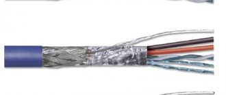
It's hard to imagine that a multi-pin connector that is made from standard polystyrene has nearly the same frequency response as a custom coaxial BNC or even a tulip. However, in fact, an attempt was made to increase the frequency properties of the connector, and in the SCART adapter, each individual transmission channel is equipped with its own shielded conductor, which allows for much more efficient isolation between signals.
Almost any cord that you buy inexpensively "on the corner" will significantly degrade the image quality. Since they usually use cheap shielded wires, while for high-quality video signal transmission a full-fledged coaxial cable must be used. The characteristic impedance of such a device is 75 Ohms.
Well-known manufacturers of cable products are actively offering their customers to purchase a SCART cable, which they are trying in every possible way to eliminate the inherent shortcomings of this standard. Such devices are significantly different from those that you can purchase in some small local stores. After all, instead of the standard black insulation on a regular wire, they use a thick, shiny harness that includes completely separate video and audio cables, as well as gold-plated contacts and metal or metallized connectors. The cost of such products is an order of magnitude higher compared to conventional products, but it is worth mentioning right away that purchasing it does not guarantee you a better image, because, in addition to the cable, the connector itself also affects the quality.
SCART-S-Video adapter
One type of connector format cannot exist, because over time technology develops and more advanced methods of transmitting information without loss appear. But the most important thing is that many manufacturers strive to reduce the size of their products, so they equip them with smaller connectors. One of these was a round format with 4 pins
S-Video. This is a small connector with a screen and two pairs of contacts. Such connectors have become used in modern types of equipment of almost all models.
Due to the emergence of new formats, it was necessary to create universal adapters to organize communication between an external device and an old generation TV. This adapter is a shielded connecting cable that combines SCART connectors with S-Video. On SCART, the wiring diagram is presented above; it does not have any particular difficulties for implementation.
SCART-RCA wiring (tulip)
An adapter such as SCART-RCA was very popular not long ago. As for televisions, VCRs and DVD players, not only all European-made equipment was equipped with a SCART connector, but much of the Asian equipment also had this connector. In Asian (Japan, South Korea) equipment, the mandatory switching connectors are composite RCA connectors, which are colloquially referred to as “tulip”. The SCART-RCA connector has not completely lost its popularity even now, since many televisions are equipped with this connector, and there is no possibility (and need) to connect analog equipment to the TV. In addition, if you need to digitize from a VCR or from old cameras, then digital cords will not help you. There is a possibility that the SCART connector with the required pinout for your case will no longer be available for sale. However, you can assemble such a connector yourself.
SCART-6RCA pinout
The composite connector (RCA) has only two contacts. The central contact goes to the signal, and the side contact goes to the ground. Therefore, knowing the pinout of the SCART connector, it will not be difficult to solder such an adapter. Let's look at an example:
In this case, we capture audio/video signals from an analog video camera and feed them to a VCR or DVD recorder, which is equipped with a SCART connector. The audio output of the VCR (DVD recorder) is fed to the receiver, and the video output is fed to the TV. In this case, you will need an adapter with SCART on one end and 6 composite connectors on the other; three of them will serve as input, and the other three will serve as outputs. It should be noted that this is the usual SCART-6RCA wiring diagram. As for colors, there are usually 2 options - three-color and six-color.
For the three-color option:
yellow—video signal; red - audio signal (right channel);
white — audio signal (left channel).
In this case, the designation input or output is written on the cord or on the tulip itself.
For the six-color option:
yellow - video input signal; red - audio output signal (left channel); white — audio input signal (left channel); black - audio output signal (right channel); green - audio input signal (right channel);
blue - video output signal.
https://01010101.ru/kommutaciya/raspajka-scart-rca-tyulpan.htmlPinout SCART-RCA2014-09-16T23:07:55+00:00adminSwitchingswitching An adapter like SCART-RCA was very widely popular not long ago. As for televisions, VCRs and DVD players, not only all European-made equipment was equipped with a SCART connector, but much of the Asian equipment also had this connector. In Asian (Japan, South Korea) equipment, compulsory switching connectors are composite connectors...admin
01010101.ru
What is scart on TV
The scart connector is needed so that you can easily connect other devices to the main information receiver. Video and audio signals come from it through the plugs. Today, almost all televisions are equipped with scart connectors. With their help, incoming digital and analog signals enter the device to reproduce images and sounds.
A scart port consists of twenty pins, each of which transmits or receives a specific signal. The edge of the scart, covered with a layer of metal, is the 21st pin, and is connected to the shielding braid of the cable. This design protects transmitted signals and neutralizes various types of interference.
Application
SCART unifies the connections between different devices; it combines all the necessary signals in one multi-pole plug. Most LCD/LED TVs available in the market are equipped with at least one SCART connector.
Through SCART it is possible to transmit analog and digital commands. For example, if you turn on the VCR, the TV automatically turns on. The CEC video equipment control protocol, transmitted via the SCART connector, has made it possible to simplify the setup of various equipment using one remote control. For example, you can use your TV remote to program your VCR to record at a specified time from your satellite or cable digital receiver.
The design of the connector makes it impossible to connect the plug incorrectly. The disadvantage of the connector is that it requires physical force to connect and disconnect it.
Contact distribution
The SCART connector has several groups of contacts
, providing the transmission of certain signals from the TV and back:
- 5 lines for transmitting and receiving audio;
- 9 lines for receiving and transmitting video signals;
- 2 lines for selecting modes;
- 3 lines for digital data transmission.
All lines are marked in different colors, which greatly facilitates the process of installation and connection of various devices. SCART is still very popular among a large number of users.
The scart implemented the ability to transmit stereo audio signals, which was later transferred to other more modern types of HDMI connectors. Due to the design features of the connector, data transfer is possible when controlled remotely. also connect unmodulated signals:
- composite;
- component;
- S-Video.
Component video signals include RGB and YPbPr. And S-Video includes 2 lines. The function of switching video signal reception modes and waking the TV from sleep mode upon command from an external device was added to the connector only in the late 80s. In the same years, SCART was supplemented with 2 video signal transmission lines S-Video.
Although the interface is large and inconvenient, many manufacturers still install it in their equipment with the expectation of using it to connect to old TV receivers
. And in order to connect other types of devices to it, for example, a video camera, you will need a special adapter.
Implementations
Multi-AV (2-channel audio, S-Video and CVBS) SCART adapters with input/output switch
Almost all modern DVD players and set-top boxes with SCART connectors can output an RGB signal, which provides superior picture quality compared to a composite signal . However, on many devices, RGB output is not enabled by default, instead defaulting to composite video: RGB often has to be adjusted manually in the menu or using switches on the back of the device.
The Nintendo GameCube, Wii, Neo-Geo, Dreamcast, PlayStation, PlayStation 2, PlayStation 3, Xbox and Xbox 360 can output RGB, component video, S-Video or composite video. These consoles come with a standard composite video connector, but manufacturers and third parties sell connectors for component video and RGB SCART connections. If the Nintendo GameCube and Xbox automatically switch to the corresponding mode, the PlayStation 2 must be told via a system menu selection whether to use YP BPR or RGB video. RGB is only available on GameCube and Wii consoles in the PAL region, while S-Video is only available on NTSC consoles.
Some versions of legacy consoles such as the Sega Master System, Mega Drive/Genesis and Nintendo's SNES are capable of outputting RGB signals, and many older home computers (Amstrad CPC, later ZX Spectrum, MSX, Commodore Amiga, Atari ST, BBC Micro and Acorn Archimedes, etc.) output RGB with composite timing suitable for SCART use, but most commonly use non-standard DIN connectors. Standard definition arcade monitors use RGB signals with SCART-compatible composite timing.
Distribution of the new format
The French connector received universal approval and became the same for almost all European and Japanese manufacturers, which is why it is still used to this day to equip various household and specialized equipment, in particular, televisions:
- video recorders;
- TVs;
- DVD players;
- digital TV set-top boxes;
- special video editing equipment and much more.
The universal connector is easy to maintain due to the separation of contacts over fairly large distances, which greatly simplifies the process of diagnosing signals and performing other manipulations. The main feature of the scart is that when using it, the connection error factor is completely eliminated. What does its special asymmetrical body shape indicate? The universal French connector is still used today as the main one for many types of equipment.
The site editors advise you to familiarize yourself with the most popular WAGO terminal blocks from the company’s official website.
Receiving a 15 kHz clock signal using software
As mentioned in the previous section, the solution to the main task when building a VGA SCART adapter is to obtain a horizontal sync signal at 15 kHz. As a rule, the solution is achieved by changing, mainly in the field of software, the settings of the video card of the personal computer. In addition, the synchronization signals must be negative, i.e. with a constant level of up to + 5V, which goes to zero during the pulse itself.
Soft-15kHz program
This interesting software for Windows XP/Vista, created by a German programmer, allows you to obtain a negative 15 kHz clock signal in a very simple way. It is compatible with most video cards and is very easy to use.
Its only drawback is that while the operating system is starting, the signal from the video card remains at 31khz, so you cannot see anything until the end of Windows loading.
Using the Soft15khz program is quite simple: after downloading, simply unpack the rar archive with the program and run it (no installation required), then click on “Install 15kHz” and restart your computer. Download Soft-15kHz (1.4 Mb, downloaded: 2,389)
PowerStrip program
This is powerful software for editing all video card parameters, including obtaining a 15 kHz clock signal. The program is not free, although it can be successfully used in the shareware version (the only drawback in this case is the presence of a splash screen that lasts about six seconds upon startup). You can download the PowerStrip program from the official website.
Scart to HDMI adapter
If the scart connector can be converted to a tulip or S-Video, then one conductor will not be enough when implementing the same manipulation to obtain an adapter for HDMI. The fact is that HDMI is a digital interface, and analog signals come out of the scart. Therefore, the adapter must be able to convert one signal to another. Special converters are used for this, so it will be difficult to make such a device yourself. It is much easier and safer for yourself to buy a ready-made scart-HDMI adapter
with power supply. The device is implemented in a small case that easily fits in the palm of your hand, so it does not require much space to be placed on the back of the T-receiver.
In computing, a serial port is a serial communication interface through which information is transmitted or output at a time. For most of the history of personal computers, data was transferred through serial ports to devices such as modems, terminals, and various peripherals.
Although interfaces such as Ethernet, FireWire, and USB all send data as a serial stream, the term "serial port" usually identifies hardware more or less compatible with the RS-232 standard, designed to interface with a modem or similar communication device.
Modern computers without serial ports may require serial converters to ensure compatibility with RS-232 serial devices. Serial ports are still used in applications such as industrial automation systems, scientific instruments, point-of-sale systems, and some industrial and consumer products. Server computers can use the serial port as a management or diagnostic console. Network equipment (such as routers and switches) often use the serial console for configuration. Serial ports are still used in these areas because they are simple, cheap, and their console functionality is highly standardized and widespread.
SCART pinouts
Different pin-configurations exist. Which confations are available depends on the video device used. Sometimes one can choose the configuration (like composite or S-video) by changing a software setting.
Two status signals define (partly) which video signals are active. A video device can use these status signals to automatically switch between internal or external audio/video signals.
| Pin | Name | Description | Signal Level | Impedance |
| 1 | AOR | Audio Out Right | 0.5 V rms | <1k ohm |
| 2 | AIR | Audio In Right | 0.5 V rms | >10k ohm |
| 3 | AOL | Audio Out Left + Mono | 0.5 V rms | <1k ohm |
| 4 | AGND | Audio Ground | ||
| 5 | B GND | RGB Blue Ground | ||
| 6 | AIL | Audio In Left + Mono | 0.5 V rms | >10k ohm |
| 7 | B | RGB Blue In | 0.7V | 75 ohm |
| 8 | SWTCH | Audio/RGB switch / 16:9, slow switch (10-12v), to force tv to switch on a mode (depends of the tv(old), sometimes set tv to AUX) | ||
| 9 | G GND | RGB Green Ground | ||
| 10 | CLKOUT | Data 2: Clockpulse Out, used in the 80s by old videotapes | ||
| 11 | G | RGB Green In | 0.7V | 75 ohm |
| 12 | DATA | Data 1: Data Out (Unavailable??) | ||
| 13 | R GND | RGB Red Ground | ||
| 14 | DATAGND | Data Ground, remote control, wired and used by old videotape recorders | ||
| 15 | R | RGB Red In/Chrominance | 0.7 V (Chrom.: 0.3 V burst) | 75 ohm |
| 16 | BLNK | Blanking Signal, fast switch (1-3v), to force tv to switch on a mode (depends of the tv(recent), sometimes set tv to AUX) | 1-3 V=RGB, 0-0.4 V=Composite | 75 ohm |
| 17 | VGND | Composite Video Ground or S-video luminance Ground | ||
| 18 | BLNKGND | Blanking Signal Ground — ground for slow or fast switch (ground for pin 8 or 16) | ||
| 19 | VOUT | Composite Video Out | 1 V | 75 ohm |
| 20 | VIN | Composite Video In / Luminance / RGB Sync | 1 V | 75 ohm |
| 21 | S.H.I.E.L.D. | Ground/Shield (Chassis) |
Two pins provide switching signals. Pin 8, the function switching pin, carries a low frequency (less than 50Hz) signal from the source that indicates the type of video present.
0V-2V means no signal, or internal bypass 4.5V-7V (nominal 6V) means a widescreen (16:9) signal 9.5V-12V (nominal 12V) means a normal (4:3) signal
Pin 16, the fast switching pin, carries a signal from the source that indicates that the signal is either RGB or composite.
0V-0.4V means composite. 1V-3V (nominal 1V) means RGB only.
The original specification defined pin 16 as fast blanking, a high frequency (up to 3MHz) signal that blanked the composite video. The RGB inputs were always active and the fast blanking signal punches holes in the composite video. The SCART connector uses this to overlay subtitles from an external Teletext decoder. 0V-0.4V means composite with a transparent RGB overlay. 1V-3V (nominal 1V) RGB only.
There is no switching signal to indicate S-Video. Some TVs can autodetect the presence of the S-Video signal but more commonly the S-Video input needs to be manually selected.
Technology and development
For those who are interested in the technical side of the issue, I’ll tell you that initially several signals were combined in scart:
- Composite (low frequency, unmodulated);
- Video (input and output);
- RGB (red, green, blue video signals);
- Bidirectional "input-output";
- Stereophonic;
- Digital (all of the above are analog).
With just one cable, it became possible to simultaneously play sound, image, record video and connect to an RGB source. This provided the highest quality picture at that time. By introducing a digital signal, it became possible to change the screen proportions, control turning equipment on and off, etc. In short, it was cool :).
A few years after its introduction, the standard received new control commands. For example, I “learned” how to wake up the TV from sleep mode or switch the method of receiving a video signal.
By the way, a component (on line 2) S-Video video signal was also added to it, where the first letter hides the word “Separate”. It broadcasts 2 signals - brightness and chrominance. I’ll make a separate post about it someday.
Later, some manufacturers of equipment with this interface began to replace RGB (analogue) with YСbСr (digital), but this was not accepted as a standard.
After so many years and in our time, SCART does not want to leave the market. Due to the fact that modern equipment is equipped with HDMI connectors, special adapters have appeared that convert the outdated standard to the new one. They are not cheap, but they can significantly improve the image - the maximum resolution is 1080p.
I bought just such a thing for myself, in the future I will also write about it in more detail, because the device is quite interesting and useful.
I will end here. I think it’s now clear to you what a scart connector is.
Please know that you are always welcome on this blog.
Advantages and disadvantages of the connector
Thanks to the connector, a clear and bright picture is available
The advantages of SCART include:
- the quality of the transmitted image is close to HD;
- control of devices connected via the SCART port using one remote control (simultaneous switching on, for example)
- clear and bright picture thanks to the component output and noise-suppressing braided cables connected to 21 contacts;
- availability of SCART-RCA cables (component or composite) or SCART-S-Video, eliminating the need to purchase additional adapters or signal converters.
The disadvantages include:
- The quality of the signal is directly dependent on the length of the cable - the longer it is, the worse it is.
- Cables with braided shielding on each wire are bulky and expensive.
- Limited digital signal transmission capabilities compared to HDMI and DVI.
- It is impossible to connect modern equipment through this port.
To summarize, we can say that SCART is a connector that was actively used 15 years ago and is “alive” now, but it is being replaced by other interfaces for connecting devices.
Therefore, the presence of SCART on the back of the TV when purchasing can be considered a pleasant bonus rather than one of the key criteria for choosing a specific model.
TV screen resolutionWhat is a CAM module for digital televisionTV or computer monitor - which is better?What to do if the TV does not connect to Wi-Fi?
Description RCA
| RCA plug |
|
RCA jack or composite (also called phono connector, or CINCH/AV connector, and also colloquially “tulip”, “bell”, AV connector) is a connector standard widely used in audio and video equipment.
The big disadvantage of such connectors is that when connecting, the signal contact pair (with voltage) is connected first, and only then the housing contacts. This can cause damage to devices at the time of connection if there is a potential difference between the cases, which often happened when connecting TVs to the TV output on video cards.
A standard RCA plug (in slang for “male”) looks like a central metal protruding contact pin with a diameter of 3.2 mm (3.18 for a 0.25 inch size), an outer open length of 9.0 mm (9.52/7. 92 mm for 0.375/0.312 inch sizes), with an internal closed length of 6.0 mm (5.56 for 0.219 inch size), surrounded by a metal round rim (8.0 mm minimum inner diameter; 8.33 for 0.328 inch size). The outer diameter of the rim depends only on its thickness and is not standardized.
The RCA (slang for "female") jack, typically a panel connector that the bezel fits over, has an outer diameter of 8.0 mm (8.33 for the 0.328-inch size) and a depth of 7.50 mm (7.14 for the 0.281-inch size). ), so the rim crimping jaws must have a slightly larger internal diameter.
In inexpensive versions, the space between the connector/collet and the rim/housing (internal insulator) is filled with simple plastic or polyethylene, in mid-price ones - with textolite washers or similar ones made of pressed fiberglass, in expensive ones - with heat-resistant Teflon or ceramics.
One of the main disadvantages of inexpensive connectors is their low heat resistance. Soldering cables with a cross-section of 0.823 mm² (18 awg) or larger requires a very long warm-up time at standard solder melting temperatures of 250 ° C - or much higher temperatures of the soldering iron tip, in order to increase the cumulative heat capacity of the tip, sometimes up to 500 ° C.
Equipment
Product contents Cable Philips SWV2255W/10 SCART-3RCA, 1.5 m
depends on the specific delivery and may be changed by the supplier without prior notice!
The technical characteristics of the product may differ from those indicated on the website; please check the technical characteristics of the product at the time of purchase and payment. All information on the site about products is for reference only and is not a public offer in accordance with paragraph 2 of Article 437 of the Civil Code of the Russian Federation. We kindly ask you to check the availability of the desired functions and characteristics when purchasing.
The Philips SWV2255W/10 SCART-3RCA Cable, 1.5 m is covered by the official PHILIPS warranty for a period of 2 years.
Scheme
SCART pinout (female)
| Pin no. | Group | Signal | General | Purpose (TV side) | Signal level (span), V | Input and output impedance | RCA connector color |
| 1 | Audio | Right OUT | 4 | Right audio output | 0.2—2 (0.5 effective) | < 1 kOhm | Green |
| 2 | Audio | Right IN | 4 | Right audio input | 0.2—2 (0.5 effective) | > 10 kOhm | Red |
| 3 | Audio | Left/Mono OUT | 4 | Left audio output (or mono) | 0.2—2 (0.5 effective) | < 1 kOhm | Black |
| 4 | Audio | GND | — | Common ground for audio channels | |||
| 5 | RGB | GND (Blue) | — | Ground for blue signal | |||
| 6 | Audio | Left/Mono IN | 4 | Left audio input (or mono) | 0.2—2 (0.5 effective) | > 10 kOhm | White |
| 7 | RGB | Blue | 5 | Blue signal input B | Spread 0.7 | 75 Ohm | |
| 8 | S&AR | Status & AR | 14 | Switching the TV to an AV source and setting the aspect ratio | 0—2 → TV5—8 → AV/9.5—12 → AV/ | input > 10 kOhm, output < 1 kOhm | |
| 9 | RGB | GND (Green) | — | "Ground" for green signal | |||
| 10 | Data2 | SCL | 14 | Data2 (I2C) clock line | |||
| 11 | RGB | Green | 9 | Green signal input G | Spread 0.7 | 75 Ohm | |
| 12 | Data2 | S.D.A. | 14 | Data2 (I2C) data line | |||
| 13 | RGB/S-Video | GND(Red/C) | — | "Ground" for red signal / Common C-channel S-Video | |||
| 14 | Data2/S&AR | GND | — | Data/Clock I2C, common | |||
| 15 | RGB/S-Video | Red/C | 13 | Red signal input/output R/C channel S-Video | Spread 0.7 | 75 Ohm | |
| 16 | FastSwitch | RGB Select | 18 | CVBS/RGB switching signal (FastSwitch), blanking signal | 1—3 (log “1”) → RGB 0—0.4 (log “0”) → CVBS | 75 Ohm | |
| 17 | CVBS/S-Video | GND(CVBS/Y) | — | Common for CVBS/Y-channel S-Video | |||
| 18 | FastSwitch | GND | — | Common for FastSwitch (pin 16) | |||
| 19 | CVBS/S-Video | CVBS/Y OUT | 17 | Composite Video Output / S-Video Y-Channel Output | Spread 0.7 | 75 Ohm | Blue |
| 20 | CVBS/S-Video | CVBS/Y IN | 17 | Composite Video Input / S-Video Y-Channel Input | Spread 0.7 | 75 Ohm | Yellow |
| 21 | Chassis | GND | — | Chassis Grounding |
Receiving a 15kHz clock signal in hardware
Let us now turn to the study of various VGA SCART adapter circuits, ranging from the simplest to the most complex. Let's start with the pinout of the VGA and SCART connectors:
Basic circuit with composite timing (ATI RADEON video cards only)
- Pros : Easy to implement, does not require any special components.
- Cons: Requires external 5V and 12V power supply, only works with certain ATI Radeon video cards.
Basically, three RGB lines are used (VGA pins 1, 2, 3) connected to the corresponding SCART pins (pins 15, 11, 7). It is also necessary to connect the common wires of each channel (of course, one common wire is enough, but for high-quality shielding it is better to use all of them). To do this, the VGA pins (6,7,8) must be connected to 13, 9, 5 SCART.
Note: these connections are always the same in all adapter circuits. The dotted brown wire that connects pins 10 VGA and 17 SCART is the common sync signal wire. The black wire connects the shielded cable sheaths of both connectors. And finally, the brown wire that goes from VGA pin 13 to SCART pin 20 transmits the composite clock signal.
ATTENTION: In order for this VGA SCART adapter circuit to work, it is very important that the video card supports the clock signal mode on pin 13, which is usually absent in most video cards and only some video cards belonging to the ATI RADEON family can support this mode of operation.
What it is?
It is quite easy to answer the question of what SCART is on a TV. This is one of the connectors designed to ensure that the television receiver is used in close conjunction with other devices.
It is equally important that the domestic radio-electronic industry quickly picked up this idea. Already in the 1980s, SCART was used very widely
These ports were connected to in different years:
- video recorders;
- DVD players;
- set-top boxes;
- external audio equipment;
- DVD recorders.
But at the initial stage of its development, SCART was not perfect enough. Even the most advanced developments of this kind in different countries suffered from interference. Remote control often caused difficulties. And for a long time it was not possible to ensure the production of cables of the appropriate standard in the required quantity. Only by the mid- or even late 1990s were SCART’s “childhood diseases” defeated and the standard gained the trust of consumers.
Nowadays such connectors are found in almost all manufactured TVs. The only exceptions are certain models that focus on newer versions of interfaces.
The port is divided into 20 pins. Each pin is responsible for a strictly defined signal. In this case, the perimeter of the SCART port, covered with a layer of metal, is conventionally considered the 21st pin; it does not transmit or receive anything, but only cuts off interference and interference.
The 8th pin is designed to transfer the internal signal of the TV to an external signal source. Using pin 16, the TV changes the composite mode to RGB or switches back. And pin inputs 15 and 20 are responsible for processing the S-Video standard signal.
Additional features
However, this turned out to be not enough, as a result of which the developers also included a large number of potential features in the interface, reserving space for new functions for the future. Since the time when the VGA-SCART adapter became one of the most popular in Europe, this standard has only just begun to acquire new properties. For example, using this interface today, you can control various TV modes, such as switching it to monitor mode and back, switching the mode of working with RGB signals, and much more. Moreover, these capabilities were previously very simple, while today SCART has the ability to transmit digital data, as a result of which the total number of commands has become almost unlimited.
Today you can find a large number of systems that provide information exchange using SCART, as a result of which the VGA-SCART adapter, as well as many others, have become very popular.
Connector pinout
Even such an attractive connector as SCART cannot be used indefinitely. It was replaced by an S-Video connection. It is still widely used in various technologies. To connect to SCART, you can use widely used adapters. The wiring diagram is shown in the picture below.
But an even simpler solution is becoming more widespread - RCA. Separate connection involves the use of yellow, red and white plugs. The yellow and white lines are responsible for stereo audio. The red channel supplies the video signal to the TV. Wiring into “tulips” is carried out according to the diagram shown in the following photo.
Quite often you have to solve another problem - how to connect the old connector and modern HDMI. In this case, you won’t be able to limit yourself to conductors and adapters. You will have to use a device that will “translate” HDMI digital signals into analog and vice versa. Independent production of such equipment is impossible or extremely difficult.
For SCART connectors, see below.
Step-by-step instructions for connecting an old TV to a set-top box
Before you begin, you need to make sure you have the connectors you need. Tulips are usually included with the digital set-top box. In this case, you can save a little and buy a SCART connector of the following type:
Another option for a SCART adapter for a tulip
The step-by-step process for connecting an old TV will be as follows:
- Connect the antenna connector to the set-top box.
- We connect the tulip type plugs to the corresponding inputs, by color.
- Find available inputs on your TV. Older devices will most likely have tulip connectors. If not, then all this can be connected to the SCART input by purchasing the appropriate adapter.
- After that, plug in the TV and set-top box. After loading, press AV mode on the TV remote control. The corresponding menu should open in which you can search for digital channels. We looked at how to do this earlier.
If, when purchasing, you notice that the tulip-type connectors do not match the colors of the inputs, then do not be upset. In this case, connect the matching forks, and try to rearrange the remaining ones when playing the console.
Today, Russia is abandoning analog television, replacing it with digital television. Not everyone is in a hurry to connect it, because for this you need to pay a monthly subscription fee, as well as buy new TVs that support innovations. However, many are wondering how they can connect an old TV to digital television while spending a minimum of money.