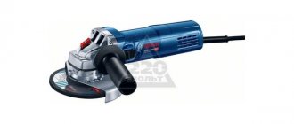
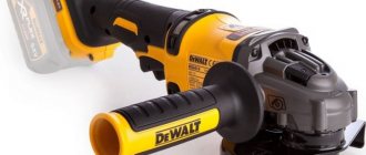
Cordless angle grinder Metabo W18 LTX 125 + 3.5 Ah LiHD + charger ASC 55 T0333 with soft start. Photo VseInstruments.ru
Grinders that are not equipped with a soft start device when starting up require additional effort from the user to eliminate dynamic loads that arise due to a sharp increase in speed of the spindle with the nozzle. Working with an angle grinder of high power, and therefore having a larger inertial mass, has safety problems during operation. Therefore, the presence of a soft start device on angle grinders is associated with a reduction in traumatic risk. The absence of high current values and, for this reason, increased forces arising in the gearbox of a power tool, significantly increases its service life .
Device, what is this element?
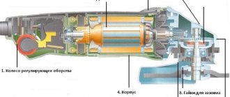
The soft starter is an electronic unit mounted into the electrical part of the angle grinder. In industrial designs, it is made in the form of an electronic board, the basis of which is a special microcircuit. The most famous and popular of them are K1182, LM358 .
The output characteristics of the electronic unit make it possible to avoid a sharp increase in starting current , thereby ensuring a smooth increase in spindle speed to operating speed. A minor disadvantage is a slight delay in the start of the technological operation.
Speed controller
Makita 9565CV angle grinder with soft start and speed control. Photo 220Volt
To increase the functionality of an angle grinder, the presence of a speed controller on it is a determining factor. require certain rotation modes of the working tool for effective execution For example, wood or plastic should not be processed at high speeds due to the increased amount of heat that can destroy the structure of the material. Grinding and polishing of various surfaces require selection of the required tool rotation speeds to obtain high-quality roughness indicators.
The speed controller, as well as the soft starter, is an electronic unit. The difference is that during a soft start, the parameters are changed automatically using a microcircuit, while the speed is adjusted manually . Such an electronic unit is called a dimmer.
How to disable the speed controller in a Bosch angle grinder
We have an angle grinder Bosch 8-125 CE (green). How to disconnect (eliminate) the speed controller board (obviously burned out) on which there are three wires? I will attach screenshots of the article, where they say that you can pull out the supply wires and install a jumper. I also provide a screenshot of my version of the regulator. The black and white wires are connected to the brushes. Blue is connected to the winding.
is it obvious?
Mutru4, checked the path starting with power. successfully moves from the switch to the windings, etc. Today the angle grinder turned on once, which means the engine is normal. but a dozen yesterday and further attempts today without results. There is no understanding where the power break is on the motor or regulator.
Alex B. wrote: Mutru4, checked the path starting with power. successfully moves from the switch to the windings, etc. Today the angle grinder turned on once, which means the engine is normal. but a dozen yesterday and further attempts today without results. There is no understanding where the power break is on the motor or regulator.
Alex B., is the cord 100% intact?
Alex B. wrote: How to disconnect (eliminate) the speed controller board (obviously burned out) which has three wires?
There are 4 wires coming out of the motor (stator), two for brushes, two for power, and connect the switch to them. Check the switch for operation; often the rod does not turn on.
I understand everything, but I don’t collect everything.
Falkon58, turned off the regulator and powered it directly. The angle grinder is working. Is it worth picking out the regulator? Perhaps not the compound itself, but a plastic wall behind it, where a view of the reverse side of the board will open. Is it possible to call and identify something without soldering it?
Alex B. wrote: turned off the regulator and powered it directly.
the direction of rotation of the disk in the direction of the arrow?
Alex B. wrote: turned off the regulator and powered it directly. The angle grinder is working
and the revolutions could grow to 14-15 thousand.
The speed is high according to the arrow. I opened it up and cleaned the regulator as best I could. Look, can you reveal something in this form? Does the simister ring when it is soldered?
Alex B. wrote: Opened it up and cleaned the regulator as best I could.
Without a switch, through the block, did you check the engine?
I understand everything, but I don’t collect everything.
rem273 wrote: and the revolutions could increase to 14-15 thousand.
Alex B., is it really not clear that at such speeds the disk can simply rip apart? And in a completely different topic you will share your impressions.
Alex B. wrote: Opened it up and cleaned the regulator as best I could.
Without a switch, through the block, did you check the engine?
Falkon58, The switch is connected and only works with the regulator unit disconnected. Accordingly, it is necessary to repair the regulator unit, since I do not plan to operate at maximum speed. That’s why the regulator cleared it for the public to see (no diagrams, no dialing skills).
Tell me, can a possible breakdown on the soldered-in red regulator block be detected? I'm afraid I'll just break it off, maybe because of the poured compound, but if I can definitely detect its breakage.
Alex B. wrote: can a possible breakdown on the soldered-in red regulator block be detected?
Connect the tester, turned on in resistance testing mode, to the two terminals of the variable resistor and begin to rotate the red wheel. If connected to the extreme terminals, then the resistance should not change. If connected to the extreme and middle terminals, then the resistance should change. Judging by the regulator diagram you provided, the resistance should change smoothly from 0 to 50 kOhm. If the regulator is worn out, then the resistance may not change smoothly, but in jerks.
Alex B. wrote: When the simister is soldered in, does it ring?
The triac cannot be checked with any testers. A simple circuit with a light bulb is assembled.
Crosser CR8E Mantis TS-350 with Lombardini diesel engine
friends, can I close the three contacts of the resistor (red regulator wheel) on the board in any way to check the functionality of the resistor? In my understanding, by closing a pair of contacts I will get the maximum resistor range (or minimum). I expect that if I close the correct contacts of the resistor, the angle grinder will start, or I will exclude the resistor option.
p/s/ Let me remind you that now when I removed (disconnected) the regulator board and ran the wires past it, my angle grinder works in the normal direction, but at very high speeds, which is not acceptable for me.
Experience with the tester I set the tester to 200 ohms. Above is a screenshot with dots. I close the legs 1.3 - the indicator does not change from rotation - it is always 1 on the screen.
I close 2.3 - the indicator on the screen is 02.1 - I start rotating slowly and see an increase in the indicator, but after 2-3 mm of rotation (I didn’t even reach the nearest number 2 - the value on the wheel) the indicator is set to -1 on the tester
I close 1.2 - I begin rotation and only at the very end (!) of rotation of the wheel the indicator changes from one and reaches 0.19, but after 2-3 mm the extreme point of rotation.
Judging by the diagram given in the first post, the resistance of the variable resistor is 50 kOhm. So you need to set the tester to the limit of 100 kOhm or higher.
rem273 wrote: Is it really not clear that at such speeds the disk can simply rip apart?
Why do you think so? If for each diameter of an abrasive reinforced cutting disc a linear speed of 80 m/s is indicated, this does not mean at all that in the manufacture of sheets for cutting blanks f 115 (15,000 rpm max.) and f 230 (7,500 rpm max.) are used different binders: this is NOT technologically advanced - and therefore NOT economical. Otherwise, the mounting dimensions of the holes for each diameter would be different - as is done on toothed disks for circular saws. It follows from this that the “recommendations” of angle grinder manufacturers about the inadmissibility of using worn-out cutting discs f 230 on 125 grinders are nothing more than a source of receiving a share of profit from the sales of disc manufacturers! On 230-k casings, I specially make cuts on both edges (“fork” on ff 120 and 125 mm) - in order to use them for finishing cleaning of 125-k: the grain size of the grinding wheels is finer than 24 units. (this is stripping, not stripping!) did not come across. If you put the cores in a bag, it won’t break during cleaning!
Block diagram of Interskol, Lepse and others, thyristor diagram, photo
As noted earlier, the basis of any soft starter is a special microcircuit . On grinders with this option, they are installed by the manufacturer. If the user wants to modify the angle grinder to equip it with a soft start function, you can purchase a separately sold unit. The DIY option also has a right to exist. Below is one of the soft start unit diagrams from the manufacturer.
The main elements of the scheme are:
- the actual microcircuit itself is based on semiconductor control thyristors;
- capacitors of various capacities;
- resistances affecting the duration of control signals;
- a power triac controlled by a microcircuit and limiting the power (speed) at the output.
The operating principle of the circuit is as follows.
- Alternating voltage from the network is supplied to the microcircuit.
- It should be noted that the thyristors from which the microcircuit is assembled begin to operate at a certain voltage. The voltage across it is formed through a capacitor, which charges with some delay. It takes some time for it to charge fully.
- The power triac will also work with a delay, since it is controlled using a microcircuit.
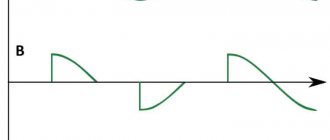
- With alternating mains current, the processes described above are carried out in half-cycles, which decrease due to the presence of residual voltages on the circuit elements. Therefore, the voltage to the electric motor of the angle grinder will be supplied smoothly, without a sharp jump.
Methods for connecting the regulator inside the angle grinder body
The speed control unit is a very compact device that easily fits inside the body of the angle grinder. On the Internet you can easily find diagrams and manuals for making such regulators. But how advisable it is to make it yourself is something everyone decides for themselves, because in online stores a ready-made block can be purchased for only 300–500 rubles. The photo below shows an electronic rotation speed controller for voltages up to 250 V and a rated current of 12 A with six-position step adjustment, standard for angle grinders. Its price without delivery is about 200–300 rubles, depending on the seller.
There is more than enough space in the grip part (rear handle) of the grinder to install a regulator with such dimensions. For low-power angle grinders, the free space is usually located closer to its end, while for more powerful ones, it is between the handle and the motor or in the handle itself (see photo below). No special skills are required to install such a regulator, since it simply needs to be connected to the power supply circuit of the electric motor of the angle grinder.
The video below shows the resuscitation of an old grinder by equipping it with a rotation speed controller. Interesting is the push-button control of the speed with memory of the value after turning off the supply voltage.
How the system works
a commutator electric motor as an electric . When it starts, a strong magnetic field is required in the windings to spin the static rotor. Therefore, the starting current is several times higher than its rated value. The soft starter is distinguished by the presence of a so-called acceleration time , during which the electronic unit smoothly spins the electric motor rotor without sudden jerks. A microcircuit based on semiconductor devices can change the phase regulation of the parameters of an electrical circuit and influence the transient electromagnetic processes that cause the rotor to rotate.
Advantages of soft starting angle grinders
Angle grinder Bosch GWS 17-150 CI Professional 0.601.798.0R6 with soft start. Photo VseInstruments.ru
Grinders with a soft start option are distinguished by the absence of the following disadvantages present in power tools without this function.
- The brush commutator pair is characterized by increased sparking, which leads to burnout of the commutator lamellas.
- For the same reason, brushes wear out faster .
- Due to the increased value of the starting current, the stator and rotor windings fail much more often .
- The general electrical network perceives the inrush current by possibly tripping the protective fuse . However, if the work is carried out, for example, from a generator, then it may fail.
- The mechanical part of the angle grinder in the form of bevel gears and support bearings , experiencing increased loads, has a risk of premature failure .
- A strong jerk when starting an angle grinder (especially high power) can tear it out of your hands and, in some circumstances, cause injury.
Do I need a soft start for power tools?
Considering the above advantages of a smooth start of an angle grinder, the answer suggests itself - it is definitely necessary . However, small household grinders belong to a category where low price is one of the priority parameters. Therefore, it does not always make sense to equip them with a start-up unit , which increases their selling price. Such inexpensive grinders are used mainly for work that does not require professional skill.
Starters for angle grinders with a 20 A triac
Devices with 20 A triacs are suitable for professional grinders. Many models use contactor resistors. First of all, they are able to operate at high frequencies. The maximum temperature of the starters is 55 degrees. Most models have a well-protected case. The standard device circuit involves the use of three contactors with a capacity of 30 pF or more. Experts say that the devices stand out for their conductivity.
The minimum frequency for starters is 35 Hz. They are capable of operating in a DC network. Modifications are connected via adapters. Such devices are well suited for 200 W motors. Filters are quite often installed with triodes. Their sensitivity indicator is no more than 300 mV. Quite often there are wired comparators with a protection system. If we consider imported models, they have an integrated converter that is installed with insulators. Current conductivity is ensured at around 5 microns. With a resistance of 40 Ohms, the model is capable of stably maintaining high speeds.
How to make a field-effect transistor and more, connect, check
The soft start method based on the use of semiconductors is the most widely used in practice. The following can be used as semiconductor devices :
- thyristors (pass current in one direction) and triacs (as if two thyristors were assembled together, as a result of which they work in both directions);
- field effect transistors;
- IGBT bipolar transistors.
In grinders, a circuit based on thyristors and triacs . In general, other options are rarely used for making soft starts and only in the case of powerful power tools.
A detailed description of how to make, connect and check a soft start yourself can be found at the link “Do-it-yourself soft start of an angle grinder”.
Models for angle grinder 600 W
For 600 W angle grinders, starters with contact triacs are used, in which the overload does not exceed 10 A. It is also worth noting that there are many devices with plates. They are distinguished by their security and are not afraid of elevated temperatures. The minimum frequency for 600 W angle grinders is 30 Hz. In this case, the resistance depends on the installed triode. If it is used of the linear type, then the above parameter does not exceed 50 Ohms.
If we talk about duplex triodes, then the resistance at high speeds can reach up to 80 Ohms. Very rarely, models have stabilizers that operate from comparators. Most often they are attached directly to the modules. Some modifications are made with wired transistors. Their minimum frequency starts from 5 Hz. They are afraid of overloads, but are able to maintain high speeds at a voltage of 220 V.

