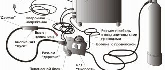
Application of butt plates
Butt plates are elements that connect the ends of the rails to each other using bolts. All linings are divided into three main groups:
- Double-headed linings are used when connecting rails of the same type. For example, only linings of the same marking are suitable for P43 rails. This greatly simplified the task of selecting linings for a particular type of rail. Identical markings help avoid confusion in names and functionality.
- Special overlays for insulating joints. A distinctive aspect of these products is the presence of an MPE 65 polymer coating. The purpose of this type of overlay is to provide impeccable electrical insulation in various areas.
- Transition pads are used when it is necessary to connect rails of different brands. During manufacture they are marked based on the types of rails for which they are used. In some cases, when it is not known which rails will need to be joined, it is possible to produce overlays without bolt holes. This is an ideal option that eliminates problems when laying railway tracks.
Any cover is provided with holes for bolts, most often their number varies from 4 to 6 pieces. The holes are made round and oval. For what? To be able to place bolts in opposite directions to ensure a tight connection.
How to find out the number of holes by marking? It's easy to do. Remember an example: linings 2Р65 , intended for rails marked P65, have four mounting holes, and linings 1Р65 - six holes, allowing you to firmly connect the rails.
Photo gallery
Basic quality requirements
The pads must be made of high-strength steel, subjected to firing and various tests in order to serve well as an element for fastening the ends of the rails. You can start checking with an external inspection of the product. The presence of dirt or uneven surfaces is strictly prohibited. Slag cannot be added to the metal composition. Cracks, delaminations, and holes at the end of the lining are not allowed. The edges of the linings that are adjacent to the base and head of the rails must be extremely smooth without any bulges.
Quality control during reinforcement works
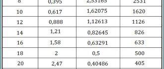
Acceptance inspection of reinforcing elements includes checking their installation, the size of the protective layer and permissible deviations. The installed reinforcement elements must comply with standard parameters (Table 2).
Table 2. Permissible deviations in the installation of reinforcing elements
Butt joints of rods made by bath or bath-seam welding, as well as T-joints of embedded parts, are partially or completely checked using ultrasonic flaw detection with possible subsequent scanning of doubtful areas with X-rays or gamma rays.
The following defects are allowed in welds:
- in joints accessible for welding on both sides, lack of penetration is up to 5% of the metal thickness, but not more than 2 mm;
- in joints accessible for welding on one side without the use of backings - lack of penetration up to 16% of the metal thickness, but not more than 3 mm;
- slag inclusions or single and group pores with a size of no more than 10% of the metal thickness and no more than 3 mm;
- a chain of slag inclusions with a total length of no more than 200 mm per 1 m of weld;
- slag inclusions or single and group pores no more than 5 pcs. per 1 cm2 of seam.
Reinforcement works are classified as hidden, therefore their acceptance is documented in acts for hidden work.
Use of used butt plates
If the pads have been repaired, their use is not permitted. Even with the use of welding, it will not be possible to restore defects to their former strength for use in the construction of railway tracks. The special requirements for manufacturing are not accidental, because the functions that are assigned to this element of the railway are very important. Connecting spans of rails to each other, while not every product is capable of withstanding large dynamic loads. Quality and compliance guarantee excellent rail connections.
Implementation of VSP elements
The railway track consists of many elements, and the overall strength and safety during future transportation of goods and people depends on each of them. Transportation by rail in Russia and other countries has significantly reduced delivery time between remote regions of our country. This is the main stage of development, which has opened up many new opportunities for the world, remaining relevant and in demand to this day. Now this system is the safest, second only to air transport in terms of transportation duration. We have not yet come up with another optimal solution. But technology does not stand still and it is not worth denying the emergence of something new or the modernization of standard railway transportation in, say, 50-100 years.
Our company offers a wide range of butt plates and other fasteners, as well as rails of various markings for the successful implementation of the plan when laying railway tracks in a wide variety of purposes and places - from underground mines to connecting roads between factories and other production enterprises.
Reinforcement of reinforced concrete structures
Reinforcement of slabs, bottoms and other similar structures begins with chalk markings based on the position of the longitudinal and transverse rods. Then the rods are laid out and connected to each other. The finished mesh is raised onto pads to provide a protective layer. With double reinforcement, the second mesh is assembled similarly to the first.
Reinforcement of structures with meshes and flat frames is carried out using cranes, which ensure the supply of reinforcement packages with a weight of up to 100 kg directly to the structure, and with a weight of more than 100 kg - laying in the design position. Flat reinforcement cages are installed in the formwork and connected to each other by distribution reinforcement. Rolled or flat meshes are installed in the formwork and secured in the design position. The joints of the mesh are mainly overlapped. In the direction of the working rods, the overlap of the mesh of smooth round rods is l > 250 mm with at least two transverse rods located in the joint area. In meshes made of periodic profile reinforcement, the presence of transverse rods in the joint area is not necessary, but the overlap length should be equal to l + 5 diameters of the working rods. In the direction of the distribution rods, the meshes can be laid either without overlap, or overlapping, or with the installation of an additional mesh covering the junction of the main meshes.
Reinforcement of structures with spatial frames and reinforced concrete blocks is carried out by laying them in fully or partially installed formwork. The reinforcement outlets of the base are preliminarily straightened and aligned according to the design and the alignment axes are applied. Then, a crane using slings or traverses lifts the reinforced elements, installs them in the design position according to pre-made markings, aligns them and temporarily secures them with guy wires. After this, the fittings are adjusted and connected, and the crane slings are released.
When installed in a structure, reinforcing bars, meshes, frames and other elements are connected by welding (electric arc and contact), tied with wire, secured with spring or plastic clamps.
Rice.
6.12. Methods for connecting reinforcing bars : a - joining bars using manual electric arc welding: I - with overlays and double-sided seams;
II - the same, with one-sided seams; III - overlap; b - arc welding with forced formation of a seam of cross-shaped horizontal connections of rods; c - the same, horizontal with vertical; d - resistance spot welding when connecting rods with an overlap; d - the same, with a cruciform connection; e - knitting with wire the intersections of the rods: 1 - at the beginning of welding: II - the same, at the end; I - connecting rods; 2 — round pads; 3 — electrodes; 4 - inventory (copper or graphite) forms; 5 - knitting wire; g - connection of rods at intersections with spring clamps: I - winding of the clamp; II - lock in working position; I - spring clamps; h - plastic clamps: I - connection of parallel rods; II, III - the same, intersecting rods. Symbols: h - the amount of settlement of the rods; a is the thickness of the connection; c' and c" - dents of the lower and upper rods, respectively; g - burr; d' and d" are the diameters of the lower and upper welded rods, respectively; lн - overlap length The connection of rods along the length by electric arc welding (except for butt welding) is done with an overlap or with overlays (Fig. 6.12, a). An overlap connection with one- or two-sided seam welding is used for reinforcement with a diameter of at least 20 mm. The total length of the seam is determined by calculation. The connection with linings is used for almost all diameters of fittings.
To make cross-shaped connections of reinforcing bars with a diameter of more than 10 mm, manual electric arc welding is used in copper or graphite forming elements (Fig. 6.12, b).
Resistance welding is used to connect reinforcing bars both lengthwise and transversely. When connecting along the length, the ends of the rods are first overlapped one on the other by 1..1.5 times the diameter of the reinforcement, and then, during the welding process, they are upset until the rods are in a coaxial position (Fig. 6.12, d). With a cross-shaped connection, the amount of settlement of the rods is taken to be about 0.5 of the diameter of the rod with a smaller area (Fig. 6.12, d). Resistance welding is performed using mobile butt welding machines.
Manual knitting of reinforcement with wire is used for small volumes of work or in cases where contact and arc electric welding is not allowed. Wire knots are knitted using reinforcement cutters or hooks (Fig. 6.12, e). For knitting, soft wire with a diameter of about 1 mm is used.
In order to speed up the connection of the rods, spring wire clamps with a diameter of 1.6...2.8 mm are used, with their help one- and two-way connections are made (Fig. 6.12, g).
TsNIIOMTP has developed methods for connecting parallel and intersecting rods using plastic clamps (Fig. 6.12, h), which simultaneously fix the thickness of the protective layer of concrete.
To ensure the required thickness of the protective layer during reinforcement, rectangular tiles made of concrete or mortar, reinforcement stops, stands, etc. are used as fasteners.
In prestressed reinforced concrete structures, rods, wire and wire bundles, wire bundles and ropes are used for reinforcement. Two methods of tensioning reinforcement are used: on stops and on concrete. In construction site conditions, tension is most often applied to concrete. With this method, reinforcement from bundles of wire is used. To secure and tension wire reinforcement, anchors of various designs are used: conical, sleeve, glass and blind. During the process of concreting a structure, channels are installed in it with a diameter of 10...15 mm larger than the diameter of the reinforcement beam being passed through. When the length of the reinforcement is up to 10 m, it is tensioned from one end, and when the length is more than 10 m - from both ends. To ensure the solidity of the structure and protect the reinforcement from corrosion, the channel is sealed by injecting a cement mortar of at least M300 into it.
Pre-tensioning of the reinforcement of tanks and other cylindrical structures is carried out using special coiling machines, which cover the walls of the structures from the outside with reinforcement after the concrete has reached its design strength. After winding the reinforcement, the outer surfaces of the walls are shotcrete or plastered with high-strength cement mortar.