The introduction of plasma processing into industry marked a technological breakthrough and a transition to a qualitatively new level of production. The scope of application of the beneficial properties of plasma is very wide. First of all, this is the production of electronics and semiconductor devices. Without plasma-chemical etching, the light would hardly be seen by modern high-performance personal computers. But that's not all.
Ion plasma processing is also used in optics and mechanical engineering for polishing products, applying protective coatings, diffusion saturation of the surface of metals and alloys, as well as for welding and cutting sheet steel. In this work, the main focus is on welding and cutting technologies using plasma.
General provisions
From school physics lessons, everyone knows that matter can exist in four states: solid, liquid, gas, and plasma. The most questions arise when trying to imagine the last state. But in reality, everything is not so difficult. Plasma is also a gas, only its molecules are, as they say, ionized (that is, separated from electrons). This state can be achieved in different ways: as a result of exposure to high temperatures, and also as a result of electron bombardment of gas atoms in a vacuum.
Such plasma is usually called low-temperature. This process physics is used when carrying out plasma spraying (etching, saturation) in a vacuum. By placing plasma particles in a magnetic field, they can be given directional movement. As practice has shown, such processing is more effective in a number of parameters of classical operations in mechanical engineering technology (saturation in powder media, flame cutting, pouring with chromium oxide-based paste, and so on).
Types of plasma treatment
Currently, plasma is actively used in almost all sectors of industry and the national economy: medicine, mechanical engineering, instrument making, construction, science, and so on.
Instrumentation was a pioneer in the use of plasma technologies. Industrial applications of plasma processing began by using the properties of ionized gas to atomize all kinds of materials and deposit them on pads, as well as to etch channels to produce microcircuits. Depending on some features of the design of technological installations, plasma-chemical etching, ion-chemical, and ion-beam etching are distinguished.
The development of plasma is an incredibly valuable contribution to the development of technology and, without exaggeration, improving the quality of life of all humanity. Over time, the scope of application of gas ions has expanded. And today, plasma processing (in one form or another) is used to create materials with special properties (heat resistance, surface hardness, corrosion resistance, etc.), for effective metal cutting, for welding, for polishing surfaces and eliminating micro-irregularities.
This list does not limit the use of technologies based on the effect of plasma on the surface being treated. Currently, means and methods of plasma spraying are being actively developed using various materials and processing modes in order to achieve maximum mechanical and physical properties.
Principle of operation
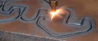
For plasma cutting of metal, a plasma jet is applied to the workpiece. Plasma is a stream of ionized gas heated to a temperature of thousands of degrees, which is electrically conductive and moves at high speed. The formation of a plasma arc from an electric one is carried out using a plasma cutter. The operating principle of the plasma cutter and the stages of the cutting process:
- A pilot electric arc is formed, which is ignited between the electrode of the plasma cutter and its nozzle or the metal being processed.
- After the pilot arc is formed, compressed gas is supplied to the chamber. It expands in volume and heats up to a temperature of 20,000 °C.
- The electric arc ionizes the gas, it becomes a conductor of electricity and turns into a plasma jet. This jet heats the metal in the processing zone, melts it and produces cutting.
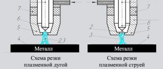
Different principles of gas plasma cutting are used for metals and non-metallic materials. There are two ways to process materials:
- The arc burns between the plasma torch and the product. This is how a direct action cutter works. The product must be conductive. If it is necessary to cut non-metallic products, the indirect method is used.
- The arc is ignited in the plasmatron itself between the electrode and the nozzle. The electrode is the cathode, and a positive potential is applied to the nozzle.
The essence of plasma welding
Unlike installations of ion-plasma saturation and sputtering, in this case plasma treatment is carried out using high-temperature plasma. The efficiency of this method is higher than when using traditional welding methods (gas flame, electric arc, submerged arc welding, and so on). As a rule, ordinary atmospheric air under pressure is used as the working gas mixture. Thus, this technique is characterized by the absence of costs for consumable gases.
Add a link to a discussion of the article on the forum
RadioKot >Laboratory >Amateur Radio Technologies >
| Article tags: | Add a tag |
Plasma cutter
Author: pnp_machinist, Published 10/30/2016 Created using KotoEd. Participant of the Competition “Congratulate the Cat as a Human 2016!”
A simple plasma cutting machine.
The importance of a plasma cutting machine for the national economy is difficult to overestimate. For example, metal savings alone when cutting are 10-15%. Not to mention the ability to cut holes and different shapes into sheet metal. The appearance on the market of welding inverters and consumables for plasma torches has made this method of metal processing accessible to the general public. In our case, dried atmospheric air with a pressure of 3.5 – 4 Atm is used as the plasma working medium. Plasmatron CUT-40 is one of the most affordable. And a welding current inverter with an output voltage of 100-140 volts, 10-40 A. This is quite enough for cutting metal 0.5 - 6 mm thick. Based on the data, the cutting current is 1 mm. metal thickness should be approximately 6 A
Theory.
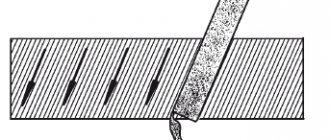
As can be seen in the conventional image of the burner, atmospheric air is both a working medium for the formation of plasma and cools the burner elements. At the first moment, the arc is ignited by a high-voltage discharge between the electrode and the nozzle, provided that the latter is in contact with the anode, i.e. metal. Next, the resulting plasma is blown out by a stream of air. To maintain a stable arc, it is necessary to maintain a gap between the torch nozzle and the metal of about 1 mm. , which is very difficult. Special attachments are available for this purpose. But according to experts, they only get in the way. I completely share their opinion and therefore simply move the torch nozzle over the workpiece without pressing. It is noticed that when there is insufficient current, the nozzle “sticks” to the metal. A successful cutting process can be judged by visible sparks on the back of the metal. At the end of cutting, you should not remove the torch; it is better to interrupt the process by releasing the tension. This extends the service life of the electrode with a hafnium insert.
Inverter
The AVT-200 inverter circuit is well suited for the power part. This inverter has already been repeated many times and is well known on the Internet. The original author’s article is available in the AVT-200.rar archive. The changes affected the unit for generating a sawtooth voltage at the current input of the comparator and the current setting circuits. Changed printed circuit board. The current setting unit is powered by a stable voltage of 15 V, which improves repeatability. To reduce the level of noise in the current comparator circuits, a resistor R90 is installed. The large inductance of the output choke makes it possible to simplify the “saw” formation circuit. Otherwise, the scheme differs little from the original. For a current shunt it is necessary to use manganin wire. In my case, with a diameter of 0.9 mm, the length of the shunt is 20 mm. Separately, I would like to note that in the diagram there is no protection unit against overcurrent and short circuit. under load. Of course, such nodes are necessary. But a short circuit is not possible in a properly assembled CUT-40 burner. Unless, of course, the nozzle completely melts and only the electrode remains.
Oscillator
In most cases, a high-voltage discharge of 20-22 kV is sufficient to successfully ignite the plasma. direct current. The spark gap circuit is the easiest to implement. To reduce the requirements on the step-up transformer, a voltage multiplier is used. The arrester is made of relay contacts, the gap is 1 – 1.5 mm. The high-voltage transformer is wound on a ferrite core with a diameter of 8 mm. 80 mm long Primary winding 7-8 turns with MGTF-0.35 wire. Secondary copper wire PEV-2 with a diameter of 1.5 mm. Impregnated with epoxy resin. Insulation between windings is required. The storage capacitor was taken from a USSR-era starter for a fluorescent lamp with a power of 80 W. As it turned out, other capacitors are 10n 6.3 kV. burn out after the 3rd ignition attempt.
Control circuit.
A simple control sequence is implemented for operation. When you press the operator button S3, 1- Air supply occurs sequentially. 2- Pause 0.5-1 sec. (this time is necessary for purging the plasma torch) 3- Turning on the inverter. 4- Turn on the oscillator for 2 seconds. When the button is opened, the inverter turns off and with a delay of 3-4 seconds. the tension is removed from the air valve. This time is enough for the burner to cool down.
In the initial state, all relays are de-energized and the operator button S3 is depressed. When S3 is closed, relay REL 2 will operate and with its contacts will close the base circuits of transistors T1, T3, T4, T6. to the common wire. Moreover, the voltage at the base of transistor T1 will appear with a slight delay due to the RC circuit R4, C1. The zener diode in the collector circuit T1 determines the threshold voltage when the transistor opens, which is also a kind of protection against interference in control circuits. Next, transistor T2 opens and the inverter turn-on relay is activated. When the S3 button is pressed, transistor T3 is closed and does not affect the operation of the circuit. At the same time, voltage is applied to the oscillator switching circuit. Positive voltage from the collector of transistor T1 through the zener diode ZD4 reaches the base T8, the opened transistor turns on the voltage supply relay to the oscillator. After the charging time of capacitor C5 has expired, transistor T7 closes transistor T8. So the operating time of the oscillator is limited to 1-2 seconds. Which is quite enough for reliable ignition of the arc in the plasma torch. The implementation of time delays for the oscillator and the air valve are implemented using similar schemes. When the S3 button is opened, the voltage is removed from the relay coil REL 2. Next, the positive voltage through resistor R16 opens transistor T3 which blocks transistor T2 and the inverter control relay is de-energized. At the same time, capacitor C4 is discharged through resistor R23 and the base-emitter junction. This way the air valve is switched off with the required delay. When you press button S3 again, the process repeats.
Details.
As it turned out, the biggest problem was blocking the air flow. For these purposes, an instrumentation valve from the times of the USSR was installed. Despite the inscription 1 atm. DN 2.5mm. It covers 4 atm with honor. The 1/4″ Intrtool PT1412 air purification filter was chosen as the most affordable. Ring inverter transformer CF138-T6325-C primary and secondary windings are wound in two wires with a diameter of 1.2 mm. Output choke on a 46x25x18 alsifer ring with 1.5 mm wire until filled in one layer. This particular throttle was selected because in my case, there is no need to use currents of more than 20 A. The high-voltage transformer is wound with 1.5 mm wire for the same reasons. The oscillator transformer is wound on an ETD-39 core with PEV-2 -0.45 layer-by-layer wire and insulation between the windings is required.
Checking the inverter.
While checking the power section, the oscillator and control circuit must be turned off. Of course, the contacts of the inverter blocking relay must be closed. Before switching on, you must check the correct installation. The power supply is checked first; it is possible to connect it separately via the JMP2 connector. Then you need to ensure the presence and correct shape of pulses with a frequency of 50 kHz. on the gates of the inverter power transistors. The "decay" time should not exceed 0.25us. The next step is to check the operation of the inverter for the equivalent load. I used two 5 kW water heating elements. connected in parallel. The maximum current is set by resistor R78. The minimum current with this circuit does not need to be adjusted. Its value is close to 10 A. At the end of the article, files SDS00003 and SDS00004 show the voltage waveforms on the collector of transistor T8 of the inverter in the absence of current and a load of 10 A.
During testing, the current in the load circuit is controlled by a dial ammeter with a measuring shunt. The ignition of the arc and the operation of the oscillator are checked with an improvised simulator. Two copper wires with a diameter of 0.8 -1 mm. connected to the anode and cathode, providing a gap of 2-3 mm. The electric arc must be reliably ignited from the first time the oscillator is turned on. In this case, the copper naturally burns and the arc goes out.
Next is a test cut of thin metal. It is advisable not to use painted ones. Use the regulator located on the filter to set the air pressure to 4 atm. Blow air through the cutter for 3-4 seconds. To do this, force open the air valve by pressing button S2. After touching the nozzle to the workpiece, press the button on the cutter handle. At the same time, for 2 sec. the oscillator turns on. And cut with the resulting plasma torch, moving the nozzle along the intended line without much pressure.
Do not neglect the basic safety rules. The magnitude of the output voltage and current can be life-threatening! Eye protection is required!
Traditionally, everything not written here is discussed on the forum.
Files:
Original article “AVT” Boards LAY6 format power circuit diagram
All questions in the Forum.
| What do you think of this article? | Did this device work for you? | |
| 99 | 0 | 3 |
| 0 | 1 |
Advantages of plasma welding
Compared to traditional types of welding, using a plasma welding machine is safer. The reason is quite clear - the use of atmospheric oxygen under pressure as a working gas. Currently, occupational safety receives very close attention from business owners, managers and supervisory authorities.
Another very important advantage is the high quality of the weld (minimum sagging, lack of fusion and other defects). Although, in order to learn how to skillfully use a plasma welding machine, many months of practice are required. Only in this case will the weld and joints as a whole meet high standards.
This technology has a number of other advantages. Among them: high speed of the welding process (productivity increases), low energy consumption (electricity), high joint accuracy, absence of deformation and warping.
What is the process of plasma metal cutting?
Plasma is a conductive ionized gas of high temperature. A jet is formed in a special device - a plasmatron. It consists of the following main elements:
- Electrode (cathode) – is equipped with an insert made of a material with high thermionic emission (hafnium, zirconium), which burns out during operation and requires replacement when more than 2 mm is produced.
- Gas flow swirl mechanism.
- The nozzle is usually isolated from the cathode by a special bushing.
- Shroud – Protects internal components from molten metal splashes and metal dust.
The air plasma cutting power source has 2 wires - the anode (with a positive charge) and the cathode (with a negative charge). The “positive” wire is connected to the rolled metal being cut, the “negative” wire is connected to the electrode.
At the beginning of the process of plasma cutting of metal, a pilot arc is ignited between the cathode and the tip, which is blown out of the nozzle, and when it touches the workpiece, it forms a cutting arc.
When the forming channel in the plasma torch is filled with an arc column, a plasma-forming gas begins to be supplied into the arc chamber under a pressure of several atmospheres, which is subjected to heating and ionization, which contributes to its increase in volume. This leads to its flow out of the nozzle at high speed (up to 3 km/sec), and the arc temperature at this moment can reach from 5000 to 30000 °C.
A small hole in the nozzle narrows the arc, which helps direct it to a specific point on the metal, which is almost instantly heated to the melting point and blown out of the cutting zone.
After passing the plasma torch along a given contour, a workpiece of the required size and shape is obtained with smooth edges and a minimum amount of scale on them.
Plasma cutting equipment
The process itself is very sensitive to the current sources used. Therefore, it is allowed to use only very high-quality and reliable transformers that demonstrate the constancy of the output voltage. Step-down transformers are used to convert high voltage input to low voltage output. The cost of such equipment is several times less than the cost of traditional converters for electric arc welding. In addition, they are more economical.
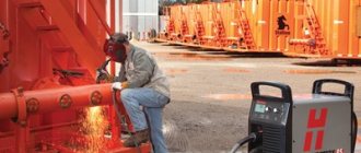
Plasma cutting equipment is characterized by ease of use. Therefore, if you have at least minimal experience and skills, you can carry out all welding work yourself.
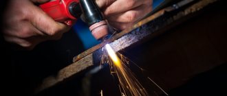
Plasma cutting
Plasma cutting is a process in which metal is cut into its component parts by a directed flow of high-temperature plasma. This technology ensures a perfectly straight cut line. After using a plasma cutter, there is no need for additional processing of the product contour (be it sheet material or tubular products).
The process can be carried out either using a manual cutter or using a plasma cutting machine for cutting rolled steel sheets. Plasma is formed when the working gas flow is exposed to an electric arc. As a result of significant local heating, ionization occurs (the separation of negatively charged electrons from positively charged atoms).
Application area of plasma cutting
A jet of high-temperature plasma has very high energy. Its temperature is so high that it literally evaporates many metals and alloys with ease. This technology is mainly used for cutting steel sheets, aluminum sheets, bronze, brass and even titanium. Moreover, the thickness of the sheet can be very different. This will not affect the quality of the cut line - it will be perfectly smooth and even, without streaks.
However, it should be taken into account that in order to obtain a high-quality and even cut when working with thick-walled materials, it is necessary to use a plasma cutting machine. The power of a hand cutter will not be enough to cut metal with a thickness of 5 to 30 millimeters.
Plasma cutting equipment
Devices for industrial and domestic use are produced for cutting metal with plasma. All plasma cutting units include:
- power supply;
- plasmatron;
- compressor for pumping compressed gas;
- cables and hoses used to connect equipment elements.
The power source may be an inverter or a transformer.
Inverter units are lightweight, economical, and have a high efficiency. They are often used in small industries. They have a current limitation of 70 A and are capable of cutting only small material up to 30 mm thick. Transformer devices are more powerful, have greater weight and size. They are more resistant to voltage surges, capable of long continuous operation and are often used in CNC machines. Equipment with a water cooling system is capable of cutting metal up to 100 mm thick. Power supplies for cutting using oxygen have a current strength in the range of 100-400 A. When using nitrogen as a plasma gas, this range increases to 600 A.
The plasma torch is the main unit of all installations. It includes:
- internal electrode;
- working nozzle;
- insulating housing with cooling;
- plasma-forming substance supply device.
Depending on the processing conditions, different gases are used for plasma cutting. For steels and alloys, oxygen and air are used. Air plasma cutting is used for processing low alloy steels. When processing non-ferrous metals, plasma-forming gases can be argon, nitrogen, and hydrogen. This is due to the fact that in an oxygen environment, non-ferrous metals begin to oxidize. A mixture of argon and hydrogen is most often used for cutting stainless steel and aluminum.
Gas cutting or plasma?
What type of cutting and cutting of metal should you prefer? Which is better: oxygen-gas cutting or plasma cutting technology? The second option is perhaps more universal, as it is suitable for almost any material (even those prone to oxidation at elevated temperatures). In addition, plasma cutting is carried out using ordinary atmospheric air, which means it does not require the purchase of expensive consumables. And the cut line turns out perfectly smooth and does not require modification. All this together significantly reduces the cost of the product and makes the product more competitive.
Flaws
Like the advantages, the disadvantages are best demonstrated in comparison with gas cutting. The disadvantages of plasma cutting include:
- More complex and bulky equipment. The so-called plasma torch, even in a portable (manual) version, is a rather large block, and it serves only as an intermediate link between the gas supply system and the cutter with a nozzle.
- Relatively small cutting thickness. This parameter directly depends on the operating current. For portable devices, the maximum thickness of a steel part is on average 20-25 mm, for industrial devices - 80-100 mm.
- Limited duration of continuous operation. Plasma torches have such a characteristic as “PV”, which is measured as a percentage at maximum current. And if the duty cycle is 80%, this means that at maximum current the device can work for 8 minutes out of 10, and cool down the rest of the time.
Plasma cutting materials
It should be taken into account that the maximum permissible thickness of the metal or alloy being processed depends on the material itself or its grade. Based on many years of production experience and laboratory research experience, experts give the following recommendations on the thickness of the materials being processed: cast iron - no more than nine centimeters, steel (regardless of the chemical composition and the presence of alloying elements) - no more than five centimeters, copper and alloys based on it - no more than eight centimeters, aluminum and its alloys - no more than 12 centimeters.
All listed values are typical for manual processing conditions. An example of such a domestically produced unit is the Gorynych plasma apparatus. It is much cheaper than its foreign analogues, but is in no way inferior, and perhaps even superior to them in quality. The market offers a wide range of devices from this manufacturer, which are designed to perform various jobs (household welding, cutting and welding of metals of various thicknesses, inclusive). Sheets of greater thickness can only be processed using high-power machine tools.
Existing plasma cutting methods
All existing plasma cutting methods can be divided into jet and arc. Moreover, it does not matter at all whether a manual cutter is used or a CNC plasma cutting and cutting machine. In the first case, all the necessary conditions for gas ionization are implemented in the cutter itself. Such a device can process almost any material (metals and non-metals). In the second case, the material being processed must have electrical conductivity (otherwise an electric arc will not occur and gas ionization will occur).
In addition to differences in the method of plasma formation, plasma processing can also be classified according to the technological features of cutting into simple (without the use of auxiliary substances), processing with water and processing in a protective gas environment. The last two methods allow you to significantly increase the cutting speed without fear of metal oxidation.
Main advantages
Plasma cutting of metals is one of the most modern and technically advanced methods of working with various metals.
This technology has emerged relatively recently, but has become widespread due to the number of advantages it offers over classical instrumental methods of working with metals.
The main advantages of plasma metal cutting are:
- cutting speed;
- versatility (you can work with any metals and alloys);
- there are no restrictions on the shape of the processed parts and the complexity of the cut out shapes;
- the cut that is formed during the cutting process has high surface cleanliness and quality.
In order to make the most of all the advantages of plasma cutting of metals, it is necessary to correctly and accurately select the operating modes of the installation for a specific material, and it is necessary to take into account many factors, such as:
- material properties;
- its thickness;
- plasma speed and temperature;
- cutting speed.
With the correct selection of these, as well as some other specific parameters, plasma cutting will be carried out quickly and with high quality.
Cutting metal using plasma is safer than conventional flame cutting, since the cutting process does not use cylinders with oxygen or flammable gases.
Plasma cutting speed table
Plasma cutting machines can have different dimensions and purposes.
Devices for manual plasma cutting are produced, but automatic plasma cutting of metal is most often used, due to the higher speed and accuracy of such equipment.
Devices for manual plasma cutting can be produced with various design features of the nozzle and cooling systems.
The most compact and versatile of them can work outdoors, in open construction or installation sites.
At the same time, plasma can be created both directly - from air, and from supplied gases, such as hydrogen or argon.
Another difference in such devices is the cooling system of the plasma torch; it can be either liquid or air.
The air system is better suited for working in open areas, but is less efficient and does not allow the device to develop truly high power.
If 20-30 years ago cutting metal with plasma was not widespread and was considered an exotic method of working with metals, today you can easily find companies that provide such services, or you can independently purchase equipment for manual plasma cutting.