GOST 23279-2012
INTERSTATE STANDARD
WELDED REINFORCEMENT MESH FOR REINFORCED CONCRETE STRUCTURES AND PRODUCTS
General technical conditions
Welded reinforcing meshes for reinforced concrete structures and products. General specifications
MKS 91.190
Date of introduction 2013-07-01
Preface
The goals, basic principles and basic procedure for carrying out work on interstate standardization are established by GOST 1.0-92 “Interstate standardization system. Basic provisions" and GOST 1.2-2009 "Interstate standardization system. Interstate standards, rules, recommendations for interstate standardization. Rules for development, adoption, application, updating and construction"
3 ADOPTED by the Interstate Scientific and Technical Commission on Standardization, Technical Standardization and Conformity Assessment in Construction (Appendix B to the Protocol dated June 4, 2012 N 40) The following voted for the adoption of the standard:
| Short name of the country according to MK (ISO 3166) 004-97 | PoMK country code (ISO 3166) 004-97 | Abbreviated name of the national construction management body |
| Azerbaijan | AZ | State Committee for Urban Planning and Architecture |
| Armenia | A.M. | Ministry of Urban Development |
| Kyrgyzstan | KG | Gosstroy |
| Moldova | M.D. | Ministry of Construction and Regional Development |
| Russia | RU | Ministry of Regional Development |
| Tajikistan | T.J. | Agency for Construction and Architecture under the Government |
| Uzbekistan | UZ | Gosarchitectstroy |
4 By Order of the Federal Agency for Technical Regulation and Metrology dated November 29, 2012 N 1306-st, the interstate standard GOST 23279-2012 was put into effect as a national standard of the Russian Federation on July 1, 2013.
5 INSTEAD GOST 23279-85 Information about changes to this standard is published in the annual information index “National Standards”, and the text of changes and amendments is published in the monthly information index “National Standards”. In case of revision (replacement) or cancellation of this standard, the corresponding notice will be published in the monthly information index “National Standards”. Relevant information, notifications and texts are also posted in the public information system - on the official website of the Federal Agency for Technical Regulation and Metrology on the Internet
1 area of use
This standard applies to welded flat and rolled meshes (hereinafter referred to as meshes), manufactured at construction industry enterprises from reinforcing steel with diameters from 3 to 40 mm inclusive, with rods located in two mutually perpendicular directions, and intended for reinforcing prefabricated and monolithic reinforced concrete structures and products.
2 Normative references
This standard uses regulatory references to the following standards: GOST 427-75 Metal measuring rulers. Technical specifications GOST 5781-82 Hot-rolled steel for reinforcement of reinforced concrete structures. Technical specifications GOST 6727-80 Cold-drawn low-carbon steel wire for reinforcement of reinforced concrete structures. Technical specifications GOST 7502-98 Metal measuring tapes. Technical specifications GOST 10922-90* Welded reinforcement and embedded products, welded connections of reinforcement and embedded products of reinforced concrete structures. General technical conditions ________________ * The document is not valid on the territory of the Russian Federation. GOST 10922-2012 is valid, hereinafter in the text. — Note from the database manufacturer. GOST 14098-91 Welded connections of reinforcement and embedded products of reinforced concrete structures. Types, designs and sizes Note - When using this standard, it is advisable to check the validity of the reference standards in the public information system - on the official website of the Federal Agency for Technical Regulation and Metrology on the Internet or using the annual information index "National Standards", which is published as of January 1 of the current year, and for the corresponding issues of the monthly information index “National Standards” for the current year. If the reference standard is replaced (changed), then when using this standard you should be guided by the replacing (changed) standard. If the reference standard is canceled without replacement, then the provision in which a reference is made to it is applied in the part that does not affect this reference.
What materials are they made from?
This classification is worth noting separately, because it is by it that the type of reinforcement network is determined. In this case, the following are distinguished:
- Metal reinforcement networks. These are the most common materials, because it is the easiest to make strong meshes from, which have high thermal and electrical conductivity. With all this, it is worth understanding that such networks are large in size. The manufacture of such networks involves the use of iron, iron alloys, steel and steel alloys.
- Plastic reinforcement networks. An extremely rare representative that has the most innovative composition. Their peculiarity lies in their low weight, high wear resistance, moisture resistance, and corrosion resistance. Also, due to the flexible material, such networks are the easiest to adapt to the structure.
- Fiberglass reinforcement networks. These models are in demand because of their versatility, because it can be used both indoors and outdoors. At the same time, this representative has the longest service life and high strength.
3 Classification
3.1 Meshes are divided: - according to the diameters of the rods; - according to the location of the working fittings.
3.2 Depending on the diameter of the rods, meshes are divided into heavy and light.
3.2.1 Heavy meshes include meshes that have rods with a diameter of 12 mm or more in one direction.
3.2.2 Lightweight includes meshes with longitudinal and transverse rods with a diameter of 3 to 10 mm inclusive.
3.3 Based on the location of the working reinforcement, meshes are divided into: - with working reinforcement in one of the directions (longitudinal or transverse) and distribution reinforcement in the other direction; - with working fittings in both directions.
4 Types, main parameters and dimensions
4.1 Grids are made of the following types (see Figures 1 and 2): - type 1 - heavy with working reinforcement in the longitudinal direction, the diameter of which is greater than the diameter of the distribution fittings; — type 2 — heavy with working fittings in both directions; - type 3 - heavy with working fittings in the transverse direction, the diameter of which is greater than the diameter of the distribution fittings; - type 4 - lightweight with transverse rods across the entire width of the mesh; - type 5 - light with displaced transverse rods.
Figure 1 - Heavy mesh
Type 1
Type 2
Type 3
Figure 1 - Heavy mesh
Figure 2 - Lightweight meshes
Type 4
Type 5
Figure 2 - Lightweight meshes
4.2 Meshes are made flat or rolled. Light meshes with longitudinal bars made of reinforcing steel with diameters from 3 to 5 mm inclusive are produced in rolls.
4.3 Nets must have rods of the same diameter in the same direction.
4.4 Grids are made with square or rectangular cells.
4.5 The diameters of the working reinforcement of the meshes are assigned based on the condition of the cross-sectional area of the reinforcement required by calculation.
4.6 The ratio of the smaller diameter of the rod to the larger one must be at least 0.25.
4.7 The main parameters of the grids are given in Table 1. Table 1 - Parameters of the grids
In millimeters
| Grid view | Grid type | Grid width | Mesh length | Rod diameters | Distance between rods (in axes) - pitch of rods | Rod release sizes | ||
| longitudinal | transverse | transverse | longitudinal and | |||||
| Heavy | 1 | From 650 to 3050 | From 850 to 9000 | 200* | 600** | 25 | Multiples of 25 | |
| 2 | From 850 to 5950 | 200 | 200 | Multiples of 25 | ||||
| 3 | From 850 to 3050 | From 850 to 6250 | 200 400 | 200* | ||||
| Lungs | 4 | From 650 to 3800 | From 850 to 9000 or up to roll length | 100 (150) 200 300 400 500 | 100 (75) 150 (125) 200 (175) 250 300 400 | 25*** | ||
| 5 | From 3950 to 9000 or up to roll length | |||||||
| * It is allowed to use rod spacing of 100 and 300 mm in the grids of standard design documentation for reinforced concrete structures. ** It is allowed to use a rod spacing of 300 mm in the grids of standard design documentation for reinforced concrete structures. ***See 2.9. Notes 1 Heavy meshes of type 1 with a width of 1500 to 3050 mm with longitudinal rods with diameters of 36 and 40 mm and type 3 with a length of 3050 to 6250 mm are produced using single-point machines and suspended welding tongs before the development of automated equipment. 2 By agreement with the manufacturer, the use of heavy mesh type 1 and light flat mesh with a length of up to 11500 mm is allowed. 3 In lightweight mesh type 5, the length of the transverse rods is from 0.85 to 0.90 of the mesh width. 4 The distances between the longitudinal and transverse rods of light mesh, indicated in brackets, may be accepted during a feasibility study. | ||||||||
4.8 The distance between the rods - the main step of the rods in one direction - should be taken the same.
4.8.1 In heavy meshes of type 1, for transverse rods at the edge of the mesh, an additional step of 100 is allowed; 200 and 300 mm.
4.8.2 In light meshes, in addition to the main step of the rods in the longitudinal direction, it is allowed to use an additional step at the edges of the mesh, as well as at the point of cutting it. The additional pitch of the longitudinal rods is taken from 50 mm to the size of the main step, a multiple of 10 mm at the edge of the mesh and a multiple of 50 mm at the point where the mesh is cut. The additional pitch of the transverse rods is taken from 50 to 250 mm, a multiple of 10 mm.
4.9 The dimensions of the outlets of longitudinal and transverse rods should be taken equal to or multiples of 25 mm in accordance with those indicated in Table 1. In light meshes made in one strip, the dimensions of the outlets of the longitudinal rods can be taken from 25 to 200 mm, multiples of 5 mm, and the dimensions of the outlets transverse rods - equal to 15; 20 and 30 mm, as well as from 25 to 100 mm, multiples of 25 mm.
4.10 Grids are designated by marks of the following structure
,
where is the designation of the mesh type (see 2.1); — designation of the name of the welded mesh (with the addition of an index for rolled meshes); , - diameters of longitudinal and transverse bars, respectively, indicating the class of reinforcing steel; , are the width and length of the mesh, cm, respectively. In the designation of the mesh brand, the following is additionally given: - for light meshes, as well as heavy meshes of type 3 with a main pitch of longitudinal rods of 400 mm after the diameter of the rods (through a dash) - the value of the pitch of the rods in millimeters; - for meshes with additional spacing - above the line or below the line, respectively, the value of the additional spacing of longitudinal or transverse rods in millimeters (in parentheses). For meshes with outlet sizes of transverse and longitudinal rods different from 25 mm, the designation of the mesh brand after the designation of the mesh length is supplemented with the following designation:
,
where , are the values of the releases of the longitudinal bars (only one value is given), mm; — value of the releases of the transverse rods, mm. Examples of symbols: - heavy mesh type 1 with longitudinal bars made of reinforcing steel class A500C with a diameter of 25 mm, with a pitch of 200 mm and with transverse bars made of reinforcing steel class A500C with a diameter of 10 mm, with a pitch of 600 mm, width 2050 mm and length 6650 mm , with releases of longitudinal and transverse rods 25 mm:
;
- flat light mesh type 4 with longitudinal bars made of reinforcing steel class A500C with a diameter of 10 mm and transverse bars made of reinforcing steel B500C with a diameter of 5 mm, with a pitch of longitudinal and transverse bars of 100 mm, a width of 2550 mm and a length of 6050 mm, with longitudinal and transverse outlets rods 25 mm:
;
- rolled mesh type 5 with longitudinal and transverse bars made of reinforcing steel class B500C with a diameter of 5 mm, with a main pitch of longitudinal bars of 200 mm and an additional pitch of 100 mm, with a pitch of transverse bars of 150 mm, a width of 2340 mm and a length of 120,000 mm, with longitudinal outlets rods 125 and 175 mm, with releases of transverse rods 20 mm:
.
What are the advantages and disadvantages of
Like all building materials, reinforcement networks have a number of advantages, including:
- High strength indicators.
- Possibility of creating various fortifications.
- Convenient and simple installation and operation process.
- High resistance to temperature changes.
- Low fire hazard.
- Possibility of strengthening various structures.
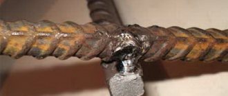
With all this, such networks have only one drawback - corrosion.
5 Technical requirements
5.1 Meshes should be manufactured in accordance with the requirements of this standard according to working drawings and technological documentation approved in the prescribed manner.
5.2 As working reinforcement in heavy meshes, reinforcing steel bars of classes A500C, A600C and A400 (A-III) with a diameter of 10-40 mm should be used. During feasibility studies, the use of hot-rolled reinforcing steel bars of class A240 (A-l), with a diameter of 10-32 mm, as working reinforcement is allowed.
5.3 As distribution reinforcement in heavy meshes of type 1, reinforcing steel of classes A400 (A-III), A500C, B500C and A600C with diameters of 6-16 mm is used, in meshes of type 3 - reinforcing steel of classes A400 (A-III), A500C, B500C and A600C with a diameter of 10-16 mm and A240 (A-l) with a diameter of 6-16 mm.
5.4 Lightweight meshes should be made from reinforcing steel of class B500C with a diameter of 4-5 mm, reinforcing wire of class Bp-I with a diameter of 3-5 mm and rod reinforcing steel of classes A400 (A-III), A500C, B500C and A240(AI) with a diameter of 6- 10 mm. As distribution fittings, it is allowed to use reinforcing steel of class B500C with a diameter of 4-5 mm and reinforcing wire of class B-l with a diameter of 3-5 mm.
5.5 The grades of reinforcing steel for the production of meshes must correspond to the grades established by the design documentation (in accordance with the requirements of building codes and regulations for the design of concrete and reinforced concrete structures, depending on the operating conditions of the structures), specified in the order for the production of meshes.
5.6 Reinforcing steel must meet the requirements: - rod reinforcing steel classes A400 (A-III) and A240 (AI) - GOST 5781; — rod reinforcing steel of classes A500C and B500C - current regulatory documents*; _______________ * In the Russian Federation, GOST R 52544 applies to reinforcing steel of classes A500C and B500C. - rod reinforcing steel of class A600C - current regulatory documents; - reinforcing wire of classes Bp-I and B-l - GOST 6727.
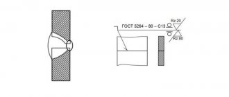
5.7 Cross-shaped connections of rods in meshes should be carried out by resistance spot welding in accordance with GOST 14098.
Welding modes must comply with the requirements of current regulatory documents.
5.8 In meshes with working reinforcement made of smooth bar reinforcing steel of class A240 (A-l), all intersections of the rods must be welded. In meshes with working reinforcement of a periodic profile (rod and wire), it is allowed to weld the intersections of the rods through one or two intersections in a checkerboard pattern, if there are no special instructions in the working drawings. The two outermost bars in the mesh must be welded at all intersections. In the reinforcing mesh, no more than two unwelded intersections of the bars are allowed in an area of 1 m of the mesh from among the intersections subject to welding.
5.9 The breaking force or temporary tensile strength of rods at welding points during a tensile test (weakened at intersections and joints) must not be lower than required by GOST 10922.
5.10 Requirements for the shear strength of welded joints of rods - in accordance with GOST 10922. If the requirements for equal strength in accordance with GOST 10922 are not imposed on welded joints of bars made of reinforcing steel of a periodic profile, located in two or one direction, then the rejection load during shear testing should be not less than 30% of the tensile strength of reinforcing wire or the tensile strength of reinforcing steel of smaller diameter.
5.11 Cross-shaped connections of the net rods should not be destroyed by impact when the nets are freely dropped from a height of 1 m.
5.12 Butt joints of reinforcing steel bars should be carried out by flash butt welding in accordance with GOST 14098. Welding modes - in accordance with current regulatory documents. Working reinforcement on a rod length of 6 m should not have more than two, and on a rod length of 12 m - more than three butt joints. Butt connections of rods in one direction within the reinforcement pitch in another direction are allowed through at least three rods.
5.13 The values of relative settlement in cross-shaped joints of rods (in fractions of the smaller diameter of the welded rods) should be for reinforcing steel classes A240 (A-l), A400 (A-III), B500C, A500C and A600C from 0.2 to 0.5.
5.14 The values of actual deviations of the geometric parameters of the meshes should not exceed the limits specified in GOST 10922.
5.15 Longitudinal and transverse rods in meshes must be straight. The values of actual deviations from the straightness of the rods should not exceed 6 mm over a rod length of 1 m.
How are reinforcing mesh made?
For a more complete and clear understanding of the structure of reinforcing masonry mesh or its analogues, you need to study the entire process of producing these meshes.
Let's take a closer look at the features and nuances of production:
- When producing such material, high precision is required, which is ensured using special equipment. It is worth noting that such machines make material of the required size, correct shape, with high strength and good appearance.
- All machines that produce welded mesh from reinforcing wire are equipped with computers that fully automate the manufacturing process.
- For some meshes that have specific sizes and sections, special machines are required that perform resistance welding.
It is worth noting that such seriousness of this process is not accidental, because each network must have high-quality parameters.
In this regard, only reliable materials are used, including:
- A variety of wires that have different markings for each type of network.
- Hot contact types of reinforcing steel.
- Types of reinforcing steel that have improved strength parameters and undergo heat treatment.
6 Acceptance rules
6.1 Grids are accepted in batches in accordance with the requirements of GOST 10922 and this standard.
6.2 In each mesh or roll selected from the batch, the following is additionally checked: - dimensions of the outlets; — straightness of the rods; — the amount of settlement of the rods.
6.3 If unsatisfactory test results are obtained for at least one of the indicators, a re-check is carried out on a double sample. The results of the re-inspection are applied to the entire batch. If, during re-checking, at least one mesh does not meet the requirements of GOST 10922 and this standard, all meshes are subject to piecemeal acceptance.
7 Control methods
7.1 Methods for monitoring and testing meshes must comply with those established by GOST 10922 and this standard.
7.2 The width and length of flat mesh, the pitch of longitudinal and transverse rods, the dimensions of the outlets, the straightness of the rod and the difference in the length of the diagonals, as well as the width of the rolled mesh, the pitch of its longitudinal and transverse rods, the dimensions of the outlets and the straightness of the transverse rods are checked with a tape measure in accordance with GOST 7502 or a metal one ruler according to GOST 427.
7.3 Cross-shaped connections for impact are checked at the mesh production and packaging stations by freely dropping the meshes from a height of 1 m onto a concrete base or metal pads.
Scope of application
Reinforcement is used in a wide variety of construction work. For each, products of the appropriate type are selected.
Rolled mesh is used for the following work:
- pouring concrete screed;
- construction of bridges;
- construction of fences - chain-link also refers to reinforcement;
- construction of wells and tunnels.
card version is more durable. Heavy meshes are used for the following purposes:
- strengthening of structures - roads, bridges, foundations, blind areas;
- floor reinforcement;
- separation of various types of bulk materials;
- strengthening masonry - brick, gas block, cinder block;
- pipe sealing;
- almost all finishing and repair work.
Conventionally, the purpose of the product depends on the thickness of the reinforcing bar and the size of the cell. In fact, the same road mesh is used for the construction of pens and fences for large animals, during repair work inside the house.