Most people who work professionally with wood would like to have all the necessary machines at their disposal. But unfortunately, this is not always possible. Some people don't have the space to do it, others, and I think the majority, it's money. Any, even the most primitive machine is quite expensive.
But what’s stopping you from just doing it yourself? Nothing is impossible for a person with intelligence. For every carpenter, a circular saw is the main tool. But it happens that only a hand saw is available, and this is not always convenient for large volumes of work. In order not to purchase a separate tool, you can make a stationary mini saw yourself for ease of work - make a sawing table (stand) for it.
Table saw
When choosing a circular saw, you need to be guided by the following characteristics:
- Saw power. If the amount of work is quite large, it is advisable to take a tool with a power of at least 1.2 kW.
- Cutting depth. The thickness of the material to be processed depends on this parameter. For hand saws it is 40–70 mm. But when installing it in a table there will be a decrease of around 10 mm.
- Button placement. The design of the sawing table must provide free and safe access to all control buttons, otherwise it will be necessary to modify the control system yourself.
- Rotational speed. For cutting wood, high rotation speed is preferred. This affects the cutting quality. For plastic, for example, this is not very good. Due to the high rotation speed of the circle, the plastic heats up. You need to choose average characteristics. 3-4 thousand rpm will be enough.
Main parameters - calculation of power, speed, gear
The characteristics of the circular saw, the engine and the maximum thickness of lumber that can be cut are interconnected. The maximum speed for which it is designed is indicated on the purchased circular disk. The number of revolutions transmitted by the engine to the shaft should be less. The engine power affects the maximum permissible saw tooth diameter. The diameter must be at least three times the thickness of the material, otherwise sawing will be difficult. It is believed that to cut materials 100 mm thick, you need a motor of at least 1 kW of power.
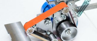
The transmission is made only by a V-belt - if foreign objects get under the saw, the material jams, the belt slips on the pulleys. Injuries in such cases are practically eliminated
It is important to choose the right gear ratio
We take into account two indicators: engine speed and the maximum permissible speed of the circular saw. We calculate the required pulley diameters. A pulley with a large diameter is installed on the engine, and a smaller one on the circular shaft to increase the number of revolutions
A pulley with a large diameter is installed on the engine, and a smaller one on the circular shaft to increase the number of revolutions.
Making a workbench
- Mark and cut a tabletop of the required size from plywood. Clean the surface with sandpaper.
- At the bottom of the tabletop we mark places for holes for attaching the saw. To do this, you need to remove the blade and install the saw in the right place, making notes. The holes for the bolts are countersunk on the surface, and the heads of the bolts need to be sanded.
- If the material will be cut at different angles, the hole for the disk should be made in the shape of an inverted trapezoid.
- Mark the places where the stiffening ribs are attached to the tabletop (from below, at a distance of about 8 cm from the edge). The legs need to be secured to the ribs. The ribs are screwed on with self-tapping screws at intervals of 25 cm and glued with PVA.
- The legs are made from timber 100 cm long. Then a screed is made from timber for additional strength.
- To be able to adjust the height of the table legs, nuts and M14 bolts are attached from below.
- We fix the saw from below.
- We attach the socket to the inside of the table. From it we pull the wire to the switch.
- We make a parallel emphasis. We cut two strips of plywood, the same length as the width of the table. The width of the stripes is 10 cm. We make the corners round. We sand both strips and fasten them with self-tapping screws. Then we cut two strips of the same length, but three times wider. We fasten them. This will be the guide. We fasten the stop and guide. We set a right angle relative to the disk. We attach the rollers.
Basic Concepts
Such equipment will have numerous rotating parts. From this we can conclude that making such a machine with your own hands will not be so easy. Therefore, when starting to manufacture it, you need to calculate your strength. If you already have some similar experience, then you will cope with the task. It is worth noting right away that you will not be able to make a jointing machine entirely from parts of your own making. Of course, it’s possible that you have a large assortment of different devices in your “bins,” but this rarely happens. First of all, this concerns the shaft with knives and bearings. They will most likely have to be purchased or even ordered. But if everything you need is available, then you can safely start designing.
Some parts for the jointer: knife shaft, knife bearings, will have to be purchased or ordered
First of all, it’s worth understanding what kind of “package” you want to receive. There may be several options:
- just a jointer. It will only perform one function;
- set of jointer and circular saw. In this case, the functionality of the machine is doubled;
- equipment capable of performing the role of a jointer, a circular saw, a grinding device, a grinding and drilling machine. Such a device will be very useful for your workshop, but it will be difficult to do it yourself.
The most optimal and easiest option is to make a jointer and a circular saw on the same bed. Plus, both tools will rotate from the same electric motor. This feature will greatly facilitate our task.
Let's look at the main components of our future tabletop jointing machine. It will include:
- Bed. This structure will support the entire machine and the equipment installed on it. To make it, it is best to use durable channels with a wall thickness of 8-10 millimeters. The bed can be made either collapsible or permanent. In the first case, all its components will be connected using bolts and nuts. If you do not need a portable machine, then the channels can be secured together by welding. This option will be more reliable. You can do without a bed if its role is played by a desktop;
- Work tool. This is one of the most important components of the machine. The jointer knives and the saw itself - it is with their help that you will saw and process the boards. The knives are firmly attached to the shaft. They must be made of reliable and strong steel. Circular saw with pobedit tips. Such a tool will last you much longer;
- The rotor is where all the tools will be attached. Without this part it is impossible to make a single machine, planer or circular saw. Finding a suitable rotor can be quite difficult, so it is better to order it from a professional turner, having previously provided it with drawings;
- Desktop. For a properly functioning machine, you need three surfaces. One will serve as a workbench for a circular saw, and the other two for a jointer. The thickness of the material for the working surface must be at least five millimeters. Multilayer plywood or metal sheets are suitable for these purposes. In this case, it is advisable to make a slight difference in height for surfaces intended for jointing. The side along which the workpiece will be fed should be a couple of millimeters lower than the side to which the already processed side will go. This difference will make work easier and significantly reduce vibration.
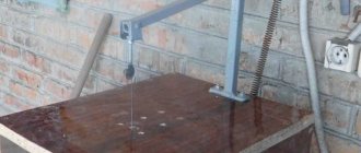
Table for hand-held circular saw with lifting mechanism
To change the depth of the cut, you can additionally install a lifting mechanism (elevator).
Read also: Soldering strands of copper wires with a torch
The lifting mechanism itself is mounted from a metal sheet that is attached to the frame on the machine. Lifting will take place along the guides by tightening the bolts.
One way is to install the adjusting rod with fixation nuts. Instead of rods, we use studs. The adjustment handle is made from a plate welded to the end of the stud. At a distance of 4–5 mm from the center we make holes for self-tapping screws. We weld a rod to the edge of the plate, which we will use to rotate the structure.
Introduction
The machine consists of three main structural elements:
- base;
- sawing table;
- parallel stop.
The base and the sawing table itself are not very complex structural elements. Their design is obvious and not so complicated. Therefore, in this article we will consider the most complex element - the parallel stop.
So, the rip fence is a moving part of the machine, which is a guide for the workpiece and it is along it that the workpiece moves. Accordingly, the quality of the cut depends on the parallel stop because if the stop is not parallel, then either the workpiece or the saw blade may become jammed.
In addition, the parallel stop of a circular saw must be of a rather rigid structure, since the master makes efforts to press the workpiece against the stop, and if the stop is displaced, this will lead to non-parallelism with the consequences indicated above.
There are various designs of parallel stops depending on the methods of attaching it to the circular table. Here is a table with the characteristics of these options.
Read also: Electric boat motor, how long does the battery last?
| Rip fence design | Advantages and disadvantages |
| Two-point mounting (front and rear) | Advantages: · Quite rigid design, · Allows you to place the stop anywhere on the circular table (to the left or right of the saw blade); · Does not require the massiveness of the guide itself. Disadvantage: · For fastening, the master needs to clamp one end in front of the machine, and also go around the machine and secure the opposite end of the stop. This is very inconvenient when selecting the required position of the stop and with frequent readjustment it is a significant drawback. |
| Single point mounting (front) | Advantages: · Less rigid design than when attaching the stop at two points, · Allows you to place the stop anywhere on the circular table (to the left or right of the saw blade); · To change the position of the stop, it is enough to fix it on one side of the machine, where the master is located during the sawing process. Disadvantage: · The design of the stop must be massive in order to ensure the necessary rigidity of the structure. |
| Fastening in the groove of a circular table | Advantages: · Quick changeover. Disadvantages: · Complexity of design, · Weakening of the circular table structure, · Fixed position from the line of the saw blade, · Quite a complex design for self-production, especially from wood (made only from metal). |
In this article we will examine the option of creating a parallel stop design for a circular saw with one attachment point.
The benefits of making it yourself
The table is made taking into account the fact that the hand tool will be installed and secured on the table, thereby turning into stationary equipment
Constructing the element with your own hands allows you to make the saw most suitable for individual conditions. There will be no difficulties in the process if you carefully study the issue. You can adjust the product to the desired size, distribute everything so that it is convenient for you.
Making a table for a circular saw is within the capabilities of every craftsman.
A handcrafted model will be one of a kind, which makes it unique.
Small table stand for circular saw
Preparing for work
Before you begin, you need to decide on the necessary set of tools and materials that will be needed during the work process.
The following tools will be used for work:
- A circular saw or you can use a jigsaw.
- Screwdriver.
- Grinding machine.
- Grinder (Angle grinder).
- Jigsaw.
- Hand tools: hammer, pencil, square.
During the work you will also need the following materials:
- Chipboard.
- Plywood.
- Solid pine.
- Steel tube with an internal diameter of 6-10 mm.
- Steel rod with an outer diameter of 6-10 mm.
- Two washers with an increased area and an internal diameter of 6-10 mm.
- Self-tapping screws.
- Wood glue.
Miniature model
To work with plexiglass, plastic, laminate, a mini-circular can be useful - a small structure similar to a stool with a disk in the center. This model is designed for thin sheets of material and will not withstand heavy loads.
You can use a grinder by attaching it to the bottom using the method described above.
For support, you can attach a beam 2 cm high.
The legs do not need to be strengthened because the device will be portable.
The motor power on the microcircular is small - up to 40 W. The disk can be taken from a hand saw, but it is quite possible to use a prefabricated structure, where a threaded rod - a construction pin - acts as a shaft. The disk is secured with a nut screwed onto the thread.
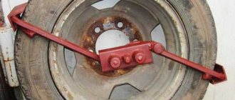
Design of a circular saw stop
The entire structure consists of two main parts - longitudinal and transverse (meaning relative to the plane of the saw blade). Each of these parts is rigidly connected to the other and is a complex structure that includes a set of parts.
The main technological solution of this stop is the principle of jamming using an eccentric and tightly pressing two transverse guides with an oblique end.
Fixation occurs by turning the eccentric mechanism.
The pressing force is large enough to ensure the strength of the structure and securely fix the entire rip fence.
The entire design is not trivial and consists of a large number of different parts, each of which has its own purpose and size.
From a different angle.
The general composition of all parts is as follows:
- Transverse part
- The base of the transverse part;
- Upper transverse clamping bar (with an oblique end);
- Lower transverse clamping bar (with an oblique end);
- End (fixing) strip of the transverse part.
- Longitudinal part
- Planar sliding element (laminated chipboard, 2 pcs.);
- The base of the longitudinal part;
- Clamp
- Eccentric
- Eccentric handle
Making a circular saw
Preparation of blanks
It all starts with the fact that it is necessary to cut the workpieces to the specified dimensions.
A couple of points to note:
- flat longitudinal elements are made from laminated chipboard, and not from solid pine, like other parts.
- Two blanks of clamping strips are made with “oblique” ends (not 90º, but 63.5º).
Thus, we get the following set of blanks.
Eccentric clamp
Let's start making an eccentric clamp that rigidly fixes the guide.
We glue two blanks measuring 80x80 mm together.
Press with a clamp and let the glue dry. In the toga you get something like this.
Using a 22 mm feather drill, we drill a hole in the end for the handle.
In the center of the workpiece you need to make a blind (not through) hole 5 mm long.
It is better to do this by drilling, but you can simply hammer it with a nail.
The circular saw used for work uses a homemade movable carriage made of laminated chipboard (or, as an option, you can whip up a false table), which is not too bad to deform or damage. We hammer a nail into this carriage in the marked place and bite off the head.
Read also: How to glue glass and plastic
Thus, we have an improvised axis of rotation for our part, called the “eccentric” (although in this case, the filled hole is located strictly at the geometric center).
Then, putting the workpiece on an axle made of a nail, we begin to grind off the corners and excess material.
As a result, we get a smooth cylindrical workpiece that needs to be processed with a belt or eccentric sander.
We make a handle - it is a cylinder with a diameter of 22 mm and a length of 120-200 mm. Then we glue it into the eccentric.
Transverse part of the guide
Let's start making the transverse part of the guide. It consists, as mentioned above, of the following details:
- The base of the transverse part;
- Upper transverse clamping bar (with an oblique end);
- Lower transverse clamping bar (with an oblique end);
- End (fixing) strip of the transverse part.
Upper transverse clamping bar
Both clamping bars - upper and lower - have one end that is not straight 90º, but inclined (“oblique”) with an angle of 26.5º (to be precise, 63.5º). We have already observed these angles when cutting the workpieces.
The upper transverse clamping bar serves to move along the base and further fix the guide by pressing against the lower transverse clamping bar. It is assembled from two blanks.
They are collected with glue.
And they are additionally fixed with self-tapping screws.
Lower transverse clamping bar
The lower transverse clamping bar is rigidly fixed to the base and serves to fix the guide by pressing against the upper transverse clamping bar.
Like the top bar, it also consists of two blanks.
We also assemble using glue and screws.
Both clamping bars are ready. It is necessary to check the smoothness of the ride and remove all defects that interfere with smooth sliding; in addition, you need to check the tightness of the inclined edges; There should be no gaps or cracks.
With a tight fit, the strength of the connection (fixation of the guide) will be maximum.
Assembling the entire transverse part
The cross guide bar of the cross guide is directly fixed to the circular table.
A transverse base is attached to this bar.
We assemble the entire structure using glue and screws.
Longitudinal part of the guide
The entire longitudinal part consists of:
- Planar sliding element (laminated chipboard, 2 pcs.);
- The base of the longitudinal part.
Planar sliding element
This element is made from laminated chipboard because the surface is laminated and smoother - this reduces friction (improves sliding), and is also denser and stronger - more durable.
At the stage of forming the blanks, we have already sawed them to size, all that remains is to refine the edges. This is done using edge tape.
The technology for edging chipboard is simple (you can even glue it with an iron!) and understandable.
The base of the longitudinal part
The base consists of four longitudinal elements, as well as two vertical ones for installing an eccentric.
If you break it down into details, you get the following diagram.
We collect the previously sawed blanks for glue.
We also additionally fix it with self-tapping screws. Do not forget to maintain a 90º angle between the longitudinal and vertical elements.
Assembly of transverse and longitudinal parts.
First you need to attach the substrate (longitudinal element) to the upper transverse clamping bar.
We fix it with glue and screws.
It's VERY MUCH here . It is important to maintain an angle of 90º, since the parallelism of the guide with the plane of the saw blade will depend on it.
Then we install the longitudinal base on the substrate.
We also fix it with glue and screws.
Installation of the eccentric
The eccentric is installed between two vertical elements on the longitudinal part.
A metal tube (future bushing) with an internal diameter of 6-10 mm must be placed in the eccentric itself.
We fix it with glue.
In addition to the bushings on the eccentric itself, you need to make similar bushings on the vertical elements, although, as an option (worst), you can use larger washers.
Additionally, a thrust block must be installed for better clamping.
Installing the guide
It's time to attach our entire structure to the circular saw. To do this, you need to attach the cross stop bar to the circular table. Fastening, as elsewhere, is carried out using glue and self-tapping screws.
We install the moving part.
All that remains is to check that the angles are correct, and we consider the work completed.
... and we consider the work finished - the circular saw is ready with your own hands.
Assembling the frame with legs
The base or frame of the table is assembled from a set of transverse and longitudinal wooden beams, which are attached to the bottom of its lid, increasing the rigidity of the entire structure as a whole. For this, four bars with a cross-section of 50x50 mm, placed at a distance of about 7-9 cm from the edge of the table, are sufficient. They are fixed on the bottom of the lid with self-tapping screws of suitable size in increments of approximately 23-25 cm. On its front side, the fastening elements are recessed into the material, completely hiding their hats. made stronger by pre-treating the mating surface of the bars with a layer of wood glue, carried out immediately before attaching them. After joining the glue-coated workpieces, the latter are securely fixed with clamps, which are removed immediately after the adhesive has dried. The legs of the structure can be made from bars of the same cross-section as the blanks for the frame (50x50 mm).
READ Make your own wood band saw
The structure of the table must be strong and rigid
The shape of the legs is chosen so that they provide maximum support area for the frame part of the base and have a shape that tapers towards the flooring. On one of these legs, controls for turning the circular saw on and off are subsequently placed, duplicating the buttons located on its body.
You will be able to further increase the rigidity and stability of the entire structure with the help of a set of steel angles mounted in the area of its butt joints. To secure them, it is recommended to use standard bolts with washers, which should preferably be installed with their heads facing outward.