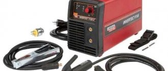
An induction soldering station is the latest equipment, widely used both among professional craftsmen and electronics specialists, and among radio amateurs of various levels. Possessing a high heating rate, durability and safety, it is used for various types of installation and dismantling soldering work on microcircuits, when installing small and overheating-sensitive SMD radio components.
Device for soldering work with induction heating
Advantages of induction soldering irons
Soldering station for Arduino
The main advantages of such soldering equipment over analogues with ceramic heating elements are:
- High heating rate – the tip of the device warms up to operating temperature in less than 30 seconds;
- Reliability and durability – soldering equipment of this type is highly reliable; if used correctly, it has a service life of more than 10 years;
- The fineness of adjusting the heating of the tip - the presence of a large number of adjustments allows you to adjust the heating temperature of the tip with maximum accuracy, which is especially important when working with expensive SMD radio components that are sensitive to high temperatures;
- Safety - unlike analogues, such devices are less susceptible to breakdowns and breakdowns of the power cable to the device body;
- Convenience - the soldering irons of such devices have a convenient shape and small size, making them well suited for soldering small parts in hard-to-reach places.
Also, such soldering devices have a very high efficiency, since the ferromagnetic layer of the tip acts as a heating element, the soldering iron practically does not lose heat and completely uses it for various soldering jobs.
From an old Soviet resistor
A soldering iron made from a resistor is designed for 6–25 V. The presence of a range is a plus: you can use different power supplies or create a stand-alone version with a battery.
What you will need:
- Soviet wirewound resistor PEV (can be obtained in workshops, radio markets, landfills, disassemblies). An option with ceramic insulation at 20 Ohms and 7 W is suitable. Other parameters are also possible. To calculate a resistor (its main parameter is resistance, Ohm), there is the equation U²/P - the planned voltage is divided by the desired power of the soldering iron;
- textolite, plywood for holder;
- two rods made of copper: along the cavity of the resistor and thinner for the tip. They can easily be brought to the desired diameter with a file;
- a ring (bite off the spring), or a split washer (grower) is a retainer;
- a regular washer and a screw for it.
Build process
Procedure:
- At the end of the rod, a thin tap is used to make a thread (horizontally) for the screw.
- At one end we cut out (using a file, etc.) a groove for the retainer. On the second, a cavity is drilled for the tip; there, to fix the tip in the copper casing, it is advisable to make a threaded hole (not shown in the images) for a screw (vertically) with which it will be clamped.
- The elements are collected.
- Everything is inserted into a resistor. At its rear end, such a heating unit is fixed with a bolt and washer.
- A handle is cut out of PCB: two plates with holes for the bolts holding them together. Preliminarily plan grooves or places for placing wiring inside.
- Solder the power supply wires to the resistor terminals.
- Collect the pen. The cable inside will be clamped between the plates, so the fixation is secure.
Assembly will be made easier if the role of the casing is not a solid copper rod that needs to be drilled, but a tube, where it is easier to insert the tip. Copper is a soft metal, so in the described part, if there is no tap, the thread can be made with the bolt itself.
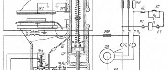
Design and principle of operation
Soldering station - operating principle and types
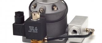
The induction soldering station consists of the following elements:
- Electronic unit with step-down transformer and generator;
- A soldering iron with an inductor heater connected to the block using a long flexible cable and a special connector.
The working part of such equipment is a soldering iron with an inductor installed inside it - a coil of copper wire wound around a socket into which the shank of a replaceable tip with ferromagnetic coating is inserted.
The design of the heating element of an induction station for soldering
The process of heating the tip with an inductor occurs as follows:
- The generator supplies a high-frequency current with a voltage of 36 Volts through the power cable to the inductor coil;
- The current passing through the turns of the inductor generates an alternating magnetic field, the lines of force of which intersect the tip shank located inside the inductor with ferromagnetic coating on the surface;
- The magnetic field, when interacting with the ferromagnetic coating on the tip shank, leads to its magnetization reversal and the formation of eddy currents. This process is accompanied by the release of a large amount of heat and very rapid heating of the shank, the trace and the entire tip to a high temperature.
The current (its frequency, and therefore the temperature of the tip) is adjusted using adjusting encoders on the electronic unit.
Ultrasonic soldering
Ultrasonic soldering is a flux-free soldering technology that does not require any chemicals and uses ultrasonic energy to solder materials such as glass, ceramics, composite materials, and metals that are difficult or impossible to solder using traditional means.
This technology is increasingly used when soldering together metal and ceramic parts included in the design of solar cells, as well as parts made of medical alloys with shape memory used in specialized electronic modules and sensor units.
Ultrasonic soldering has been mentioned since 1955 as a method for soldering aluminum and other metals without the use of flux.
This technology differs significantly from ultrasonic welding. The latter uses ultrasonic energy to join parts without adding any fillers, while traditional (and ultrasonic) soldering uses external heat to form the joint to melt metal fillers, i.e. solders. In this case, ultrasonic soldering can be performed using either a special soldering iron or a special soldering bath.
This process can be carried out either automatically during mass production or manually during prototyping or repair work.
Ultrasonic soldering was originally intended for joining aluminum and other metals, but today, with the advent of active solders, a wider range of metals, ceramics and glass can be soldered.
This technology uses either ultrasonic soldering irons with a tip with a diameter of 0.5-10 mm, or ultrasonic soldering baths. These devices use piezoelectric crystals to generate high-frequency (20-60 kHz) sound waves in layers of molten solder or in a bath of molten solder to mechanically destroy oxide films formed on the surfaces of the melt. In this case, the tips of ultrasonic soldering irons are simultaneously connected to the heating element, while the piezoelectric crystal is thermally insulated to prevent its destruction.
The tips of ultrasonic soldering irons can heat up to 450 °C during mechanical vibrations with a frequency of 20-60 kHz. Such a tip is capable of melting metal fillers of solder by exciting sound vibrations in the molten solder. At the same time, vibration and cavitation (pore formation) in the resulting melt allow solders to wet the surfaces of many metals and adhere to them.
The energy of sound waves generated by the tip of an ultrasonic soldering iron or an ultrasonic solder bath causes cavitation in the molten solder, which mechanically destroys the oxide films located on top of the layers of the solder itself and on the metal surfaces being joined.
Cavitation in a bath of molten solder can very effectively destroy oxide films on the surfaces of many metals, but it is ineffective when soldering to ceramics and glass, since the latter are themselves oxides, as well as to other non-metallic composite materials that cannot be destroyed, since they are base substance. In case of soldering directly to glass and ceramics, metal fillers for ultrasonic soldering must be doped with active elements such as indium (In), titanium (Ti), hafnium (Hf), zirconium (Zr), and rare earth elements (cerium/Ce, lanthanum/La and lutetium/Lu). Solders doped with these chemical elements are called "active solders" because they directly act on glass or ceramic surfaces to create adhesion to them.
Ultrasonic soldering technology is increasingly used due to its cleanliness, lack of flux and compatibility with active solders, and is intended for joining parts that do not allow the use of aggressive flux or consist of dissimilar materials (metals, ceramics or glass).
For effective adhesion to surfaces, the active solder's own oxide film, formed during its melting, must be destroyed, and ultrasonic vibration is well suited for this purpose.
Heating control principle
DIY soldering station
In induction soldering stations, 2 methods are used to control the temperature to which the soldering iron tip is heated:
- Using a temperature sensor built into the tip, a thermocouple placed in the tip sends signals to the electronic unit, which, based on the received data and established adjustments, heats the device tip to a certain temperature;
- Using replaceable tips (cartridges) - most modern models of such soldering devices come with several replaceable tips that have a ferromagnetic coating that loses its magnetic properties at a certain temperature.
On a note. The technology of using replaceable cartridge nozzles with ferromagnetic coating, which ensures heating of the tip to a certain temperature, is a development and is called “Smart heating”, or “Smart heat”.
Replaceable nozzles (cartridges) with ferromagnetic coating
The first method is found in inexpensive semi-professional models. Its main advantages are relative cheapness and ease of adjustment. The second technical solution is used in more expensive, high-quality and reliable models of professional soldering stations.
I have long wanted to buy a station, but due to financial problems the opportunity did not arise, and after a little thought I decided - is it possible to make it with my own hands?
I scoured the net a little and found this video https://www.youtube.com/watch?v=wzGbTwlyZxo. The station is just what I need - controlled by a microcontroller, output of data to a 16x2 LCD display on which it is displayed.
The top line is the set temperature of the soldering iron and the current temperature on it, the data is updated several times per second (0-480°C)
The bottom line is the set temperature of the hair dryer, the current temperature on it (0-480°C), as well as the rotation speed of the fan built into the hair dryer (0-99)
Board and circuit
You can download the printed circuit board (+ circuit diagram and firmware) here, everything is original, like the author.
A few tips for those who are too lazy to watch the videos (although I explained everything in some detail in them)
The dimensions of the printed circuit board have already been established; there is no need to mirror it either. It is advisable to replace the terminals through which the controls are connected to the board, that is, instead of terminals, use the usual method - take the wires and solder them into the corresponding holes on the board.
During etching, it is MANDATORY to check sections of the board with the template, since in some places the leads of SMD components can form a short circuit, all this is clearly visible in the photo
An ATMEGA328 type MK is the same microcontroller that is found on programmer boards with an arduino uno kit; in China it costs a penny, but with an MK you will need either a homemade programmer or a native arduino uno, as well as a 16 MHz quartz resonator.
The MK is fully responsible for controlling and outputting data to the LCD display. Control of the station is quite simple - 3 variable resistors of 10 kOhm (the most common, mono - 0.25 or 0.5 watts), the first is responsible for the temperature of the soldering iron, the second is the vein, the third increases or decreases the speed of the cooler built into the hair dryer.
The soldering iron is controlled by a powerful field-effect transistor, through which a current of up to 2 Amps will flow, therefore it will heat up, and the triac will also heat up - it, along with the transistor and a 12-volt stabilizer, was wired to a common heat sink, and the housings of these components were additionally insulated from the radiator.
Be sure to take 3mm LEDs with low consumption (20mA) due to the use of more powerful 5mm LEDs (70mA), my hair dryer did not work, or rather it did not heat up. The reason is that the LED on the board and the LED that is built into the optocoupler (it actually controls the entire heating unit of the hair dryer) are connected in series and there was simply not enough power for the LED in the optocoupler to light up.
Soldering iron
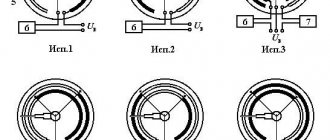
I myself took a Ya Xun soldering iron for stations of this type, 40 watts with a durable tip. The plug has 5 pins (contact holes), the pinout of the plug is below
Please note that the photo shows the pinout of the plug on the soldering iron itself.
The soldering iron has a built-in thermocouple, the data from which is received and decrypted by the station itself. You MUST need a soldering iron with a thermocouple, and not with a thermistor as a temperature sensor.
The thermocouple has polarity; if the thermocouple is connected incorrectly, the soldering iron will reach its maximum temperature after turning on and become uncontrollable.
Hairdryer
In principle, the power can be from 350 to 700 watts, I advise no more than 400 watts,
That's enough for any needs. The hair dryer also has a built-in thermocouple as a temperature sensor. The hair dryer must have a built-in cooler. It has an 8-pin socket, the pinout of the socket on the hair dryer is presented below.
Inside the hair dryer there is a 220 Volt heater itself, a thermocouple, a fan and a reed switch, the latter can be immediately thrown away; it is not needed in this project.
The heater does not have polarity, but the thermocouple and cooler do, so be sure to observe the polarity of the connection, otherwise the motor will not spin, and the heater will reach its maximum temperature and become uncontrollable.
power unit
Any (preferably stabilized adapter) 24 Volts minimum 2 Amperes, I advise 4-5 Amps. Universal chargers for laptops are perfect, they have the ability to adjust the output voltage from 12 to 24 Volts, protection against short circuits and a stabilized output - and it costs a penny, I chose this one myself.
You can also use a low-power power supply for 24 Volt LED strips, available with a current of 1 Ampere.
You can also slightly modify the electronic transformer (as the most budget option) and implement it into the circuit; I explained in more detail about power supplies at the end of the video (part 1)
You can also use a transformer power supply - it may not be stabilized, but I repeat - it is desirable to have stabilization.
Installation and housing
The case is from a Chinese radio, the 16x2 display fits perfectly with it, all controls are installed on a separate plastic sheet and docked to the bottom of the radio.
The main power components are reinforced to the heat sink through additional insulating gaskets and plastic washers. The heat sink was taken from a non-working uninterruptible power supply.
It heats up, but only after working for a long time with a hairdryer at high power, but all this is tolerable, by the way - the board provides an additional 12 Volt output for connecting a Cooper, so that you can blow off the radiator if there is a need for it.
Settings
In principle, to set up you need either a thermometer or a tester with a thermocouple and the ability to measure temperature.
First, you need to set a certain temperature on the soldering iron (for example, 400 degrees), then press the thermocouple to the soldering iron tip to understand the real temperature on the soldering iron tip, and then simply using a trimmer resistor on the board (slow rotation) we achieve to compare the real temperature on the soldering iron (which is displayed) with the one shown by the thermometer.
The same thing needs to be done with a hairdryer, only the thermometer needs to be placed under a stream of hot air.
I highly recommend that you take multi-turn trimmer resistors for convenient and precise adjustment.
By the way, the third trimmer on the board is responsible for the display contrast.
Minuses
To be honest, I didn’t notice, the design is universal, convenient, simple, and at the same time we get a professional soldering station for any needs, for which great respect goes to the author.
Main advantages and costs.
The price category of such stations is around 100 - 150 $, we have full control of a hair dryer and soldering iron and a fairly smart filling that displays all the data on an LCD display; in budget stations, instead of a display, there are ordinary LED indicators.
Smart control system for the hot air gun - when you turn off the hair dryer itself, the cooler will work until the heater cools down, then it will turn off by itself, also a very thoughtful safety solution, which is available on all profs. stations.
It is also possible to adjust the cooler speed.
Both in the case of a hair dryer and in the case of a soldering iron, the maximum temperature is 480 degrees.
On account of costs
- You can buy a soldering iron here
- Hairdryer here
- Hair dryer attachments here
- Arduino board with MK here
- LCD display here
- A set of soldering iron tips is here
- Power supply here
PS this article was published in half an hour, if I missed anything, forgive me.
Choosing the right model
The main criteria for choosing such equipment for soldering are the following:
- Power – the most convenient and practical models of soldering stations are those with adjustable power in the range from 5 to 60 W;
- Frequency of current in the inductor - for radio amateurs and semi-professionals, a device with a current frequency of 400 to 700 KHz is sufficient. Professionals and craftsmen use models with values of this characteristic up to 13.5 MHz;
- Type of heating control - most of the modern equipment of this type is produced with regulation of the heating temperature of the tip using the “Smart heat” technology;
- Number of independent channels – in order to be able to connect, in addition to a soldering iron, thermal tweezers, the device must be equipped with 2 independent channels;
- Dimensions and weight – for convenient operation and carrying, the device should be small in size and weigh no more than 1 kg;
- Also, when choosing, take into account the possibility of post-warranty repair of the device, the availability of additional components that make the soldering process more convenient.
How to make your own “Moment” soldering iron from a house-saving lamp
It is necessary to find used components from old household electrical appliances:
- Converter (ballast) from a fluorescent lamp. Enough power 40 W;
- Working transformer;
- Copper wire 2-3 mm in diameter;
The case, or rather the manufacturing technology, is not important. Device diagram:
In fact, everything that we see on the circuit diagram to the left of transformer Tr1 is part of the ballast from the energy-saving lamp. The device is complete; there is no need to modify it or change components.
The characteristics of the converter are quite suitable for a medium-power pulsed soldering iron. The safety of the design is enhanced by a standard fuse and overheating control using a thermistor. The circuit turns out to be compact and can be placed in any housing.
The working transformer is made independently. A ferrite ring from a broken electronic transformer is suitable for this. The size must be sufficient to accommodate the windings. We wind the primary from 0.5 mm wire. The number of turns is 100-120.
The secondary (power) winding is made of wire with a cross-section of 3-3.5 squares. We make one turn. A soldering iron tip made of copper or nichrome wire 1.5 - 2 mm is attached directly to it.
IMPORTANT! The thickness of the secondary winding must be greater than the thickness of the tip.
A pulsed soldering iron made from an energy-saving lamp is ready. All that remains is to come up with a convenient housing for it, install a switch, and you can quickly repair electrical appliances.
Is it possible to make an induction soldering station with your own hands?
The wide variety of models of such equipment makes its independent production practically impractical and costly; it is easier to buy a simple Chinese device, which at a low cost will have a fairly long service life and good soldering quality.
Therefore, you can make an induction soldering iron with your own hands solely out of scientific interest, having studied the internal structure of such a device and the physical phenomena occurring in it in more detail and clearly.
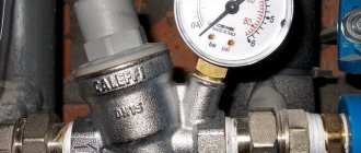
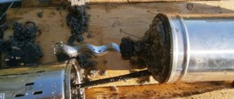
Taking measurements using an induction soldering station
Monitoring soldering temperature using a thermocouple and multimeter
When soldering various small radio components, in accordance with the requirements of various regulatory documents, recommendations of manufacturers of electronic components, safety precautions, the temperature of the tip when it touches the working surface should not be higher than 2700C. When working with the described soldering equipment, this indicator is set using adjusting encoders on the electronic unit of the device. Check the correctness of this setting by touching the tip of the device with the tip of a thermocouple connected to a multimeter.
Additional equipment
In some models of this soldering equipment, the extended package includes the following tools and accessories:
- Thermal tweezers;
- Soldering iron holder;
- A set of replaceable nozzles for different temperatures.
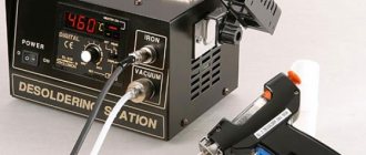
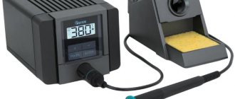
Also, some expensive soldering stations have a small display on the electronic unit that displays the temperature of the device tip.
Thus, a soldering station with an inductor heater is equipment that has many advantages. This makes it in demand and popular among both specialists and ordinary radio amateurs.