To produce compressed air, any air compressor uses atmospheric air as a feed stream. When the pneumatic station is turned on, the air flow enters the chamber of the screw block through the suction valve.
Thanks to this device, the pneumatic station is able to function, since air from the surrounding space enters the compression chamber, where the main process for which any type of air compressor is used takes place.
Compressor valves - what are they?
An air compressor is a unit whose operating principle is based on compressing and supplying air to pneumatic equipment under the required pressure. Such installations are an indispensable element both in everyday life and in industry, being an autonomously functioning technical unit or being included in more complex electrical appliances (for example, climate control or refrigeration equipment). The schematic diagram of any compressor includes a working chamber and a valve system. And since these devices, like any other mechanisms, can break down, you need to know how they are designed, what types of valves there are, how to choose them correctly or make them yourself. More on all this in the material below.
What to pay attention to
Before purchasing a valve, first take into account such a circumstance as the intensity of the existing air flow. In other systems it may be liquid or gas. This circumstance directly affects the startup and error-free operation of the installed valve.
In addition, you need to take into account that the performance coefficients of the air purifying unit are interrelated with the power data of the pumping device, be it a pump or a fan. When choosing a valve, take into account the temperature conditions in the room and the environment in which the device will be installed. The level of environmental pollution is also significant. For example, a unit of the “butterfly” variety, when exposed to a stream of cold air, begins to significantly slow down. This can lead to poor fusion between the duct and the mechanism as a whole. The cost of the valve can fluctuate insignificantly and directly depends on the technical parameters and the company that developed the mechanism .
Types and principles of operation of valve mechanisms
Currently, the most common types of compressors are screw and piston units. At the same time, screw compressors, for example, those produced by the Belarusian plant REMEZA, are widely used in various industries, and piston compressors are used in everyday life. The latter can be found both in garages of car enthusiasts (compressors such as SO-7B, Forte VFL-50, etc.) and in life support systems for fish in aquariums (Resun compressors, etc.), as well as in household pneumatic tools.
Piston compressors are characterized by a simple design and a relatively small number of parts and components. There are many different designs of such compressor units, equipped with special plate valves that regulate the process of suction and injection of air during operation . Depending on the purpose of compressor units (their performance, power and operating pressure), three types of valve mechanisms can be found:
- disk - their plates can be made of both metal and high-quality polymers, including reinforced ones;
- ring - parts for them are made of cast iron, steel or non-ferrous metals (the choice of material is determined by the type of compressor);
- disc valves - plates for this type of valve are made of polymer materials and are used in compressors operating with contaminated media.
Inlet and exhaust valves
Inlet and outlet valve assemblies play such a role in the operation of compressor equipment.
- The movement of the piston to bottom dead center causes air to be drawn in through the open suction valve.
- When the bottom point is reached, the piston begins to move in the opposite direction. At the same time, the suction valve closes, and the air in the sealed chamber begins to decrease in volume under the influence of piston pressure.
- When approaching top dead center, the discharge valve opens and air compressed under high pressure begins to flow into the receiver.
- Having displaced the air from the chamber, the piston again begins to move to the bottom dead center, and the working cycle is repeated.
Unloader and safety valves
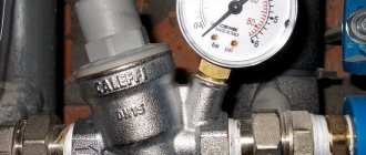
Thus, the compressor pumps air into the receiver cycle by cycle until the specified pressure value is reached. This process is monitored by a special pressure switch (pressostat), which controls the operation of the electric motor by turning it on and off depending on the degree of air compression. As a rule, the pressure switch also includes a starting unloading valve. A pressure switch is connected between the output of the compressor head and the check valve (return valve), which is connected to the receiver and holds the compressed air there.
Important! The safety valve is responsible for relieving air pressure. Its functions include: ensuring a smooth start of the compressor and preventing the return of compressed air to the compression chamber after the engine is turned off.
The necessary pneumatic equipment is connected directly to the receiver, which can be additionally equipped with various devices (separators, filters, pressure equalizers, etc.).
Repair kits for intake valves
We can supply you with the following repair kits:
- intake valve repair kits;
- control units for intake valves;
- pneumatic cylinders for intake valves;
- solenoid valves.
| Product name | Installation location |
| 510.0163 | intake valve R20E |
| 510.0363 | intake valve R40E |
| 510.0564 | intake valve R90E |
| 510.0360 | intake valve RH100E |
| 510.5760 | intake valve RH250E |
| 510.0160 | intake valve RB60E |
| 510.0360 | intake valve RB80E |
| 510.5160 | intake valve RB115E |
| 510.7160 | intake valve RB115P |
Any screw compressor includes a loading system for pumping atmospheric air into the operating unit. Controlling the operating modes of the compressor unit, monitoring the output of the unit, and regulating the injection of air into the screw assembly is provided by an important part called the inlet valve. It keeps the compressed air from reversing, ensures consistent pressure reduction during breaks in machine operation and ensures normal functioning of the compressor module.
Check valve
A check valve (return valve) is a device that allows compressed air to flow in only one direction . Structurally, it is assembled (see figure) in a metal case (item 3), inside of which the following are located:
- internal shutter (item 6), blocking the inlet;
- a spring (pos. 4) pressing the rubber ring (pos. 5) to the bolt seat;
- inlet fitting (pos. 7);
- plug (item 1) with a sealing gasket made of cardboard (item 2) (the plug makes it possible to disassemble the return for repair or maintenance).
On a note! The check valve has a branch for connecting it to the receiver and a small branch for connecting a pressure switch.
Operating principle
The reverse action valve works as follows. Passing through the outlet valve of the piston cylinder, the compressed air enters the return pipe through the inlet fitting (pos. 7). Having reached a certain pressure, the air lifts the internal shutter (pos. 6) and passes through the cavity in the housing (pos. 3) into the storage tank of the receiver. When the compressor is turned off, the spring (item 4) returns the internal shutter to its place, blocking the path of air from the receiver back into the piston cylinder.
Varieties
On the domestic market you can find compressors with returns made of three different materials: aluminum, plastic and brass. At the same time, the aluminum part differs from its analogues in its high reliability and durability. It is built inside the air duct that connects the piston cylinder to the receiver, and is capable of operating under high temperature conditions (up to 200°C). Whereas a plastic return line is installed in budget models operating at a low temperature of the working environment. As for valves made of brass, they are widely used. Such return valves are quite reliable and perfectly maintain their performance characteristics in cases where the air temperature during compression does not exceed 140°C.
Recommendations for selection
If the compressor return line fails, it is not difficult to replace it with a similar one. However, before you buy a new valve, you need to pay special attention to the diameter of the threads cut on the outlets of its body . After all, the connecting dimensions of the return, compressor and receiver may differ from each other.
Advice! When going for a new check valve for your compressor, do not forget to take the failed part with you. This will greatly facilitate the selection procedure for a new node.
It is also necessary to take into account the technical characteristics and operating conditions of the compressor. After all, there are valves that are not designed to work with high-pressure compressor equipment. In addition, when the working medium heats up to a high temperature during compression, the use of plastic returns is impractical - it is better to purchase a unit in a metal case, which is mounted inside the air duct connecting the compressor and the receiver. It will not be superfluous to purchase a collapsible design - this will allow you to buy the appropriate repair kit in the future and fix the return fault yourself, replacing the failed parts with purchased spare parts.
Features of the functioning of the suction valve
The suction valve has some design features. This is not only a restriction of air access to the pneumatic unit. For some diesel-powered mobile compressors, the inlet valve may also provide air flow to cool the engine. In this case, the compressor design provides an additional valve, which sucks air from the housing into the screw block.
In most models, the suction valves are equipped with air filters, making it possible to operate compressor stations in dusty environments. With a properly functioning valve, the compressor can be manually moved to idle mode and back to load mode. This is a kind of damper that can be in two positions - open or closed.
If the suction valve is faulty, problems are inevitable. It may not provide a sufficient flow of atmospheric air, and this will cause a decrease in the performance of the pneumatic station. To prevent this from happening, it is advisable to pay attention to the valve during every compressor maintenance.
Range
The catalog presents positions of suction valves intended for installation in air compressors from leading manufacturers of compressor equipment. The operation of the units depends on how efficiently the air flow intended for compression is supplied.
Here are devices that are installed in front of the compressor unit, as well as in other places in compressor structures where air supply is needed. All devices have been tested and have a certificate of compliance with the operating requirements and ensuring the functionality of pneumatic system equipment.
Safety valve
The relief valve (another name is safety) valve serves for emergency release of pressure and is the final device that protects the pneumatic equipment connected to the compressor from damage.
Attention! It is not recommended to operate the compressor without a safety valve.
Experts also include the following types of relief valve:
- bypass valve;
- unloading valve.
Despite minor design differences, their operating principle is identical to a safety valve.
Operating principle of the safety valve
Compressor equipment that is not intended for use in industrial environments is equipped with spring-loaded safety valves. When such a compressor operates in normal mode, it is closed (see diagram). In this case, the air pressure on its plate is balanced by a calibrated spring, which prevents the locking mechanism from opening. If the pressure suddenly increases above the set value, the pressing force of the plate against the nozzle decreases and the valve begins to open. This releases excess air, after which the locking mechanism can return to its place.
Important! If the relief valve does not return to its place for a long time, then the compressor must be turned off and the cause that caused the unauthorized increase in pressure must be eliminated
Bypass valve
The bypass (or overflow) valve maintains the pressure of the working medium at a given level. To do this, through the existing branch there is a constant, and not one-time or periodic, as in a safety valve, removal of an excess amount of the working medium (compressed air, gas, liquid), which ensures pressure stability in the system. Such valves are used, for example, in turbochargers installed on automobile internal combustion engines.
Unloading valve
The unloading valve ensures the release of compressed air remaining in the manifold between the piston block and the return line when the compressor stops. In this case, the pressure at the compressor outlet is reduced to atmospheric pressure. In general, the presence of an unloading valve makes it possible to:
- relieve pressure in the line when the compressor is turned off;
- transfer the compressor to zero capacity in the absence of flow of working fluid;
- facilitate restarting of both the compressor and the connected pneumatic equipment.
In addition, the unloading valve is used in cases where it is not possible to turn off the mechanical drive of the connected pneumatic equipment . Install it at the compressor outlet in front of the return line.
So, the more productive and powerful the compressor equipment, the more complex the valve system. The simplest check valve for use in a household low-pressure compressor can be made by yourself. But for the installation to work correctly, it is recommended to purchase a factory-made part.
Discharge valves
Discharge valves perform the following functions:
- in systems with open nozzles, they prevent the penetration of gases from the working cylinder into the cavity of the high-pressure pump;
- disconnecting the fuel line and the cavity of the high pressure pump during the suction code of the pump plunger, thereby ensuring improved filling;
- contribute to obtaining a sharp end of injection and reducing injector leakage;
- ensure the creation of residual pressure in the fuel injection line in systems with closed injectors, which in some cases contributes to better control of the injection process and more strict maintenance of injection phases;
- make it possible to reduce the residual pressure (valve with relief belt) in the fuel injection line and thus eliminate fluctuations in it after the end of injection;
- make it possible to adjust the feed characteristic, bringing it closer to the desired one.
Valves are classified according to their design:
- mushroom-shaped
- cylindrical
- lamellar
- combined
- double discharge valves
Rice. Designs of discharge valves: a-d - mushroom-shaped, e, f - cylindrical, 1 - nut; 2 - limiter; 3 - spring; 4 - valve; 6 - pump housing; 7 - suction belt; 7 - guide; 8 - valve body, gasket
Repair of screw compressors and prevention of equipment malfunctions
see also
Screw compressors are a type of rotary equipment. The principle of their operation is based on the rotation of two rotors, which are called screws.
The first screw compressor was developed by the Swedish scientist Eliot Lysholn, a sample was released in 1934. Since then, the invention has undergone many changes, but the principle of its operation remains the same.
VMC intake valves
Trading House AERO offers inlet valves for screw compressors manufactured by the Italian company VMC from a warehouse in Mytishchi. Correspondence table between old and new intake valve models
| power, kWt | New model | Old model |
| 4/5,5 | RH30 3/4″ | RH5 |
| 11 | RH30 1″ | RH10 |
| 18,5 | RH38 | RH25 |
| 22 | RH38 | RH25 RH40 |
| 22 | RH60 | RH25 RH40 |
| 30 | RH60 | R40 |
| 18,5/22/30/37 | RB60 | R40 |
| 37 | RB60 | R90 |
| 45/55 | RB80 | R90 |
| 75 | RB80 | RH100 |
| 90 | RB90 | RH180 |
| RH250 | ||
| 100/132/160 | RB115 | RH350 |
| 250/215/350 | RB200 | RH600 |
Specifications
| Model | Nominal diameter, mm | Compressor power, kW | Productivity, m3/min | Execution | Weight, kg |
| RH30 | 20 or 30 | 4-11 | 0,2-1,8 | E, NR | 0,3 |
| RH38 | 38 | 7,5-22 | 1,2-3,5 | E, NR | 0,8 |
| RH60 | 62 | 22-37 | 3-7 | E, NR, P, PM | 1,5 |
| RB60 | 6 (60) | 22-37 | 3,5-7 | PM, E, NR | 2,2 |
| RB80 | 8 (80) | 45-75 | 6-12,2 | 3,0 | |
| RB90 | 9 (90) | 90 | 7-15 | 6,5 | |
| RB115 | 11,5 (115) | 110-160 | 15-27 | 10,0 | |
| RB125 | 12,5 (125) | 132-200 | 17-32 | 11,0 | |
| RB140 | 14,0 (140) | 180-250 | 20-40 | 12,3 | |
| RB200 | 2*14,0 (140) | 250-350 |
Design and principle of operation of a screw compressor
The screw compressor converts electrical energy into air-gas thrust.
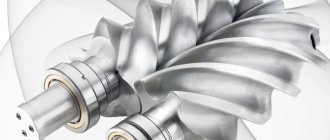
The main component of this device is the screw block (see figure below). It consists of a housing (1) and a screw pair located in it (2 and 3) - a driving and driven rotor.
In the middle part of the rotors there are thickenings on which a screw profile is cut. The teeth of the driving rotor are convex and wide, while the teeth of the driven rotor are thin and concave.
The rotor pair is mounted on bushings or bearings; a minimum gap is provided between the screws (from 0.1 to 0.4 mm). The rotors rotate towards each other, observing the sliding principle. Their movement is synchronized using gears (4) mounted on the rotor shafts. The tightness of the housing is ensured by oil seals and gaskets.
The compressor housing also has cavities for cooling (5), into which, if provided, liquid (water, oil) is supplied.
The operating principle of a screw compressor is as follows.
After the rotor pair begins to rotate, air begins to flow through the inlet port and the suction regulator, which fills the screw cavities along the entire length. Further turning of the screws reduces the volume of the working chamber and increases the pressure in it. When the screw cavities are connected to the compressor outlet, the compressed medium through the cooling radiator exits through the outlet window of the unit.
In the oil version of the compressor, the air at the stage of entering the rotor unit is mixed with purified oil, which enters it in precisely dosed portions. Before exiting, the compressed mixture passes through a separator cartridge. Oil fractions are separated from the air and returned to the rotor unit.
In oil-free compressors (dry compression), due to the strong heating of the air, compression occurs in two stages with intermediate cooling. The compression module of such devices consists of two screw blocks on a common frame. They are equipped with channels for supplying coolant. The water-glycol solution is forced into the air by a pump and then cooled in a heat exchanger. To ensure the highest possible tightness of the unit, the rotors of oil-free compressors have an increased rotation speed (up to 6,000 rpm), which is ensured by a gear multiplier.
Main types
Check valve mechanisms are divided into:
- straight view;
- corner;
- spring;
- ball;
- installed using flanges;
- casement;
- installed by soldering;
- produced for beading.
Still, there is one main drawback: such an air valve is placed on the absorption tank and has a very negative effect on the combined cooling capacity.
In any case, regardless of the type and intended purpose of the mechanism, you must carefully ensure that foreign particles do not fall on the clearance part. Otherwise, even when in the closed position, the shut-off valve will not be able to fully guarantee its functionality.
In order to install any of them (meaning a type of valve), you must take into account the setup and configuration of the system. In addition, these installations are distinguished based on the specifics of their shape (square and round) and the product from which they are made. Each of the products used has its own specifics. Based on this, many mechanisms are equipped with units made using plastic, and some with metal units.
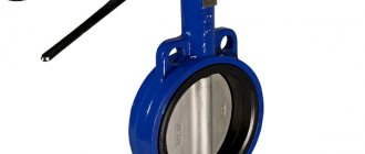
Nowadays the most popular type is the plastic valve. The throughput capacity of this mechanism is up to 6 m/s. This value is achieved due to the noiselessness when switching on and off the operating components. Such a modification of the unit can operate either with the help of a valve supplied for exhaust, or independently. It should be noted that this variety is not very popular among buyers due to being replaced by more economical analogues. Today you can purchase the most popular type of valve for compressors - the so-called “butterfly”.
These devices are made using metal, and the top is treated with a thin galvanized layer. The mechanism is equipped with two rotating blades, which are attached to the central axis. When the exhaust manifold is disconnected, the parts become short-circuited. The butterfly valve is sold in several versions, the dimensions of which range from 31 cm.
Types of screw compressors
Currently, many different types of screw compressor devices are manufactured. They can be classified according to various criteria: by filling the chamber, by compressible medium, type of drive, etc.
The two main types of screw compressors are oil-filled models and oil-free devices.
Oil-filled compressors are most often used in production shops. The operation of their rotors is softened by oil injection. It also helps remove excess heat.
Oil-free compressors are used in those industries that require high-purity compressed air: food, pharmaceutical, chemical and others.
There are oil-free dry compression compressors and water-filled devices. The former are equipped with synchronous motors, which are driven by both propellers. They dissipate heat worse than oil-filled ones, and therefore have lower performance.
Water-filled compressors use ordinary water instead of oil, which minimizes the thermal load on the parts. The service life, reliability and safety of such devices are much higher than those of dry compression compressors. At the same time, they are cheaper than oil ones - due to lower energy consumption and lower maintenance costs (replacing oil filters, containers for used oil fluid, etc.).
According to the compressible medium, compressors are air, gas and multi-purpose, according to the type of drive - belt and direct, according to the type of energy used - diesel and electric.
Depending on the degree of air/gas compression, low (up to 1 Mn/m2), medium (up to 10 Mn/m2) and high (more than 10 Mn/m2) pressure compressors are distinguished.
Suction valve - Great Encyclopedia of Oil and Gas, article, page 2
Suction valve
Page 2
Suction valves (band type) are one of the least reliable compressor components. [16]
The suction valve (nozzle) is placed at the beginning of the suction pipeline and is attached to it using flanges. It consists of a foot valve and a mesh. The purpose of the foot valve is to hold water while priming the pump before starting. There are mainly two types of foot valves used: poppet type and flapper type. [18]
The suction valve is made of 0 25 mm thick alloy steel and has a petal shape. With its holes, it fits freely onto two pins of the cylinder block and is pressed against the valve plate. [20]
The suction valve is leaking (Fig. [21]
The suction valve is springless, the working plate in it lowers and rises under the influence of inertial forces that arise when the piston moves down and up. When the piston, having reached top dead center, changes direction and begins to move downward, the valve plate, by inertia, tends to continue moving upward, and the valve opens. When the piston stops at bottom dead center and then begins to move upward, the suction valve plate continues to move downward, closing the hole in the valve seat. [22]
Suction valves are located in the upper part of the piston, discharge valves are located in the valve cover. The compressor connecting rods are steel, I-section, with Babbitt liners in the lower heads and bronze bushings in the upper ones. The piston pin is steel, hollow, free-floating. The finger is limited from longitudinal movement by spring rings. In the 2FV-19 compressor, one connecting rod head is fixed on each shaft elbow, in the 4FU-19 compressor there are two heads. On the outer cheeks of the shaft there are cast iron counterweights, which serve to balance the inertial forces that arise during the translational movement of the pistons. They reduce vibration that occurs at high speeds. The shaft rests on two rolling bearings. The shaft sealing is achieved by a membrane seal with metal friction rings and an oil seal. The moving parts of the crank mechanism are lubricated under pressure from a submerged gear pump. This pump arrangement eliminates the need for a hand pump to pump oil when starting the machine. A dirt trap and shut-off valve are mounted on the compressor suction line. [23]
The suction valves are single-ring, springless, inertial, located in the upper part of the piston. [25]
Suction valves (see Fig. 35) are plate-type, annular, springless, located in the bottom of the piston. Plate discharge valves with springs are placed in false covers, pressed to the cylinder body by a buffer spring. [26]
Suction valves are of the direct-flow type, installed in the sockets of the compressor spacer and attached to it using pressure flanges. [27]
The suction valve is open until the very end of the suction stroke. During the discharge stroke, the suction valve is also open for a while. [28]
Suction valves (under the plungers) and discharge valves 3 are the same in type and size, have a two-way direction and a rubber seal. Seat 5 and valve plate are hardened. [thirty]
Pages: 1 2 3 4 5
www.ngpedia.ru
Advantages of screw compressors
The main advantages of screw compressors are their compact size, not too much weight, reliability and durability.
- Can work offline for a long time
- Equipped with an automatic shutdown system in case of an accident, overheating or network failure
- Quickly mounted in their own frames without a special foundation
- During operation they create a minimum of noise and vibration due to insulating casings
- Equipped with digital control units that make it easy to change pressure, program cycles and regulate energy consumption
- Due to the use of screw units of the latest generations and automatic control of air supply, they significantly save energy (up to 30%)
- Do not require frequent maintenance (for comparison, piston devices must be inspected every 500 hours of operation, screw devices - after 4000-8000 hours)
The excellent performance of the screw compressor is explained by the absence of valves and a simple lubrication and cooling system. Practice shows that during the operation of one such device, an enterprise can replace about 5 piston-type machines.
Suction valve - pump - Great Encyclopedia of Oil and Gas, article, page 3
Suction valve - pump
Page 3
The cone of the suction valve 6 fits tightly into the seat 7; a gripping rod 4 with a catcher 5 is attached to the body of this valve, which is designed to lift the NSN-2 pump to the surface of the suction valve. NGN-1 pumps with an extension pipe and an extended cylinder sub are assembled from cast iron bushings and are produced with a diameter of 43; 55 and 68 mm; 28 and 32 mm pumps have cylinders assembled from steel bushings. [31]
The upper discharge valve assemblies in the NGN2 pumps and the discharge valve assemblies in the NGN1 pumps are the same. The design of the suction valves of the NGN2 pumps differs from the design of the suction valves of the NGN1 pumps only in that the tip of the catcher with a pin is screwed into the cage. Valve glasses are made of steel and plastic. Pumps of the NGN2 type can also be supplied with valve assemblies designed by Kostychenko. [33]
When pumping liquid with a downhole rod pump, the shut-off element of the pump suction valve is lowered onto the seat, the suction valve closes under the action of the liquid column in the pump pipe string and the spring force. The rod of the suction valve of the pump, which is the plunger of the dispenser, moves downward, displacing the chemical from the dispenser cylinder into the suction cavity of the downhole sucker rod pump through the opened discharge valve, while the suction valve of the dispenser closes. As the reagent is consumed, the pressure in the container decreases. [34]
During the downstroke, the entire rod-plunger system descends through the liquid. Therefore, at first the pump suction valve will be closed and the discharge valve will be open. [35]
It was already noted above that to protect pumps from large solid objects getting into them, nets with holes measuring 2 - 3 mm are installed. Sometimes, instead of a mesh, a pump suction valve design is used, in which the role of the mesh is played by a nozzle with holes with a diameter of about 5 mm. Further, depending on the adopted system with or without sediment, filters included in the fuel system are used in different ways. [36]
The design of the discharge valve assembly is similar to that of the suction valve, but has a reduced size. In practice, the discharge valve of a larger pump serves as the suction valve of a smaller pump and vice versa. The plunger assembled with the discharge valve assembly is hydraulically tested to the appropriate design pressure. [37]
Various methods and devices have been developed for pumping viscous emulsions. Some of them make it possible to reduce the resistance in the suction valves of pumps by increasing the diameter of the seat. Others suggest the use of weights and, due to this, reducing the bending of the rod column during the downward stroke. Reducing the viscosity of the emulsion is achieved by supplying chemicals using various dosing devices, similar to those used in paraffin-containing wells. Here is a description of the technologies and devices used for pumping viscous liquids. [39]
The upper discharge valve assemblies in the NGN2 pumps and the discharge valve assemblies in the NGN1 pumps are the same. The design of the suction valves of the NGN2 pumps differs from the design of the suction valves of the NGN1 pumps only in that the tip of the catcher with a pin is screwed into the cage. Valve glasses are made of steel and plastic. Pumps of the NGN2 type can also be supplied with valve assemblies designed by Kostychenko. [40]
The installation works as follows. When a well pump sucks in liquid, the plunger and the shut-off element of the pump suction valve rise, which, in turn, facilitates the flow of formation fluid from the well through the holes into the pump cylinder. The chemical reagent from the container, due to the upward movement of the plunger, enters through the opened valve 11 of the dispenser. The dispenser discharge valve closes. [42]
During the process of flushing the well, which was carried out for 3 hours, it was discovered that one of the pumps was not working normally: the suction valves of the pump were clogged. The pump was stopped for repairs while the second pump continued to work on the well. When fastening the nuts of the suction valve cover, after checking its operability, the gasket between the flanges of the discharge tee and the hydraulic box of the pump was pierced, and the driller's assistant, who was at the pump, was thrown out by the stream of escaping clay solution and suffered a broken arm in the fall. [43]
The coefficient / cn takes into account the decrease in the actual performance of the pump compared to the theoretical one due to fluid leaks when valves are delayed in closing, in the stuffing box seals between the piston and the cylinder, and for other reasons. With good care of the pump and its correct installation relative to the receiving tank (it is desirable that the liquid level in it is higher than the level of the pump suction valves), the flow coefficient reaches 0.95 or more. [44]
The pump uses flat spools. The air distribution mechanism operates in the same way as the steam distribution mechanism of twin steam pumps. The pump's pressure and suction valves are spring-loaded poppet valves. [45]
Pages: 1 2 3 4
www.ngpedia.ru
Oil-free screw compressor maintenance
First of all, it should be noted that rotary compressors of any type, and oil-free ones in the first place, are not intended for very dusty rooms.
Abrasive particles entering the screw block damage the surfaces of the rotors and disrupt the geometry of their shapes. As a result, the rotating screws begin to touch, which causes increased friction, scoring and seizing.
Many manufacturers apply special protective coatings to rotors to protect against wear and corrosion.
