A step-down transformer is the basis of a simple welding machine. A more complex welding machine is one that has a rectifier at the output that converts alternating voltage into direct voltage. Such welding machines are called rectifiers.
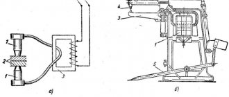
There are three types of transformers: toroidal, rod and armored, the differences between them can be seen in the figure above.
The most complex is the welding machine, which first converts the input power frequency of 50 Hz into a direct voltage, like rectifiers, and then converts it into an alternating voltage, the frequency of which is measured in kilohertz. This is an inverter.
Only someone who is well versed in radio electronics and the element base used there can make an inverter with their own hands. For this specialist, there is no need to explain why the inductor is needed and where its place is in the circuit. It would be advisable to explain to an unprepared person what a transformer and a rectifier for it are.
Principle of operation
The main property of an inductor, which is a magnetic circuit wound under certain conditions around a ferromagnetic core, is the stabilization of current strength over time.
Simply put, voltage applied to the coil causes a smooth increase in current output. Changing the polarity leads to the same smooth decrease in current.
The main factor is the condition that the current passing through the inductor cannot sharply increase or decrease. This is precisely what determines the value of using a choke for welding - resistance compensation allows you to avoid sudden jumps in amperage.
This allows you to protect against accidental burning of the workpieces being welded, reduce spattering of the melting metal and accurately select the current parameters for welding for a given metal thickness. The chances of getting a good weld using a welding choke are much higher.
The parameter that determines the current change coefficient is inductance. It is measured in H (henry) - in 1 second at a voltage of 1 V, only 1 A can pass through a choke with an inductance of 1 H.
The number of turns on the coil directly affects the amount of inductance. It is directly proportional to the number of turns squared. But if you need to make a welding choke with your own hands, then it is not necessary to calculate the exact number of turns.
Since the parameters of welding machines for household use are mostly standard and well-known, a welder will only need to use the instructions below to make a choke with his own hands.
How to make a choke for a DC welding machine
Welding with direct electric current is widely used not only in large-scale industries, but also in home workshops. The modern market offers dozens (if not hundreds) of machines for welding using an electric arc, ranging from compact low-power welders to industrial high-performance units. Regardless of the type of equipment used for electric welding, they all have one problem in common - an uncontrolled voltage drop, which makes igniting the arc and forming a seam difficult.
To solve this problem, craftsmen came up with a choke, which is introduced into the circuit with welding equipment. Beginner welders will immediately have many questions: “What is this part and how does it function? How to make a throttle for your device yourself? How to calculate the throttle correctly? In this article we will try to answer these and many other questions.
general information
What is a throttle for? This small part, connected to a circuit, ensures smooth ignition of the arc and maintains its stability even with voltage fluctuations, in addition, the metal practically does not spatter, the weld is of higher quality, you can fine-tune the device and weld thin metal without any problems.
The principle of operation is simple: the choke passes current through itself, accumulating it from the welding machine. The accumulated current is used to compensate for the lost voltage. Also, the bias choke provides the required current resistance if the voltage is too high.
It is not at all necessary to buy a throttle in a store, especially since it is far from a cheap purchase. This unit can be made independently. Its design consists of a core and two windings with a cross-section designed to operate with a certain value of direct current. This is why it will not be possible to make a universal choke, because a small part cannot cope with a powerful welder, and vice versa. So it is important to correctly calculate how many windings will be needed to work with a particular voltage.
Current adjustment
Adjusting the welding current is extremely important for proper operation and the formation of a high-quality seam. This can be done in several ways:
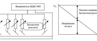
- Adjusting the current by changing the distance between the elements of the welding machine. The most popular way. To reduce the current, spread the cut transformer core apart. The induction will dissipate somewhat, and the current strength will become less. The larger the welding unit, the greater the ability to regulate the current, because the adjustment interval directly depends on the available size in the machine body.
- Adjusting the current on the transformer winding. In this way, it is possible to cut off part of the coil, thereby increasing the voltage value, allowing the current to flow along a shorter path. To weaken the current, the path must, on the contrary, be increased.
- Current adjustment using a steel spring with terminals fixed at a specified interval. This is a good adjustment method, it allows you to smoothly adjust the current, but there is one significant drawback - the spring gets very hot and is constantly under the master’s feet, and this is a gross violation of safety regulations.
Purpose
In an inverter for welding, a choke is needed to create an electric arc on the electrode. Ignition occurs when a certain voltage level is reached.
The welding choke increases the resistance, which shifts the phases between current and voltage and allows for smoother ignition. This fact in itself often allows one to avoid burning through the workpiece, especially if parts made of thin sheet metal are welded.
A smooth change in current makes it possible to avoid damaging the workpiece by abruptly applying too much power, to optimally set the arc temperature and, accordingly, to prevent metal spattering while maintaining the required processing depth.
Another valuable property is its partial protection against unstable voltage in the network.
A choke for a welding inverter greatly facilitates ignition of the electrode, which should light up at a higher voltage than the inverter produces.
An example is the MP-3 electrode, which must have a voltage of 70 V to ignite. An output choke for welding can make working with this electrode much easier for an inverter, which produces only 48 V at idle.
This occurs due to the phenomenon of self-induction. The device induces EMF (electromotive force), which causes air breakdown and flashing of the welding arc, as soon as you bring the additive a few millimeters from the metal surface.
The choke for welding is connected to the secondary winding of the transformer in the machine. It can be used in devices of any type - both home-made and factory-made, operating on any principle - inverter, with a step-down transformer, and the like.
Calculation of the cross-section of the wires of the primary winding of the transformer
Diagram of a welding transformer.
The theory of transformers is complex in that it is based on the laws of electromagnetic induction and other phenomena of magnetism. However, without using complex mathematical apparatus, it is possible to explain how a transformer works and whether it can be assembled independently.
The transformer can be manually wound on a metal core assembled from transformer steel plates. It is easier to wind on a rod or armored core than on a toroidal one. You should immediately note that the image clearly shows the difference in the thickness of the wires: the thin wire is located directly on the core, and a larger number of turns is clearly visible in it. This is the primary winding. The thicker wire with fewer turns is the secondary winding.
Without taking into account the power losses inside the transformer, let's calculate what the current I1 should be in its primary winding. The ideal network voltage is U=220 V. Knowing the power consumption, for example, P=5 kW, we have:
I1 = P:U= 5000:220=22.7 A.
Based on the current in the primary winding of the transformer, we determine the diameter of the wire. The current density for a household welding transformer should be no more than 5 A/mm2 of wire cross-section. Therefore, for the primary winding you will need a wire with a cross section of S1 = 22.7:5 = 4.54 mm2.
Using the cross-section of the wire, we determine the square, its diameter d without taking into account the insulation:
d2=4S/π=4×4.54/3.14=5.78.
Taking the square root, we get d=2.4 mm. These calculations were performed for copper wire cores. When winding wires with an aluminum core, the obtained result must be increased by 1.6-1.7 times.
For the primary winding, copper wire is used, the insulation of which must withstand high temperatures well. This is fiberglass or cotton insulation. Rubber and rubber-fabric insulation is suitable. Wires with PVC insulation should not be used.
How to independently and beautifully create a living room design?
Materials for production
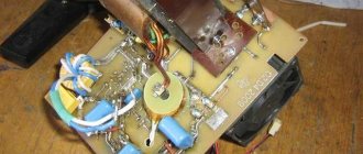
The choke for retrofitting a semi-automatic device or inverter can be assembled with your own hands, using structural elements from old equipment - tube TVs, old street lamps and other devices that have a transformer.
Structurally, it consists of a core made of a material that conducts a magnetic field, but does not conduct electric current, or is reliably insulated, and three layers of windings separated by a dielectric.
As a basis for the core, either a special material is suitable - ferrite, which has these properties, or a yoke (horseshoe) from an old transformer. Winding of the device for welding is done with aluminum or copper wire with a cross-section of 20-40 mm.
If aluminum is used, the wire cross-section must be at least 36 mm; copper wire can be thinner. A flat copper busbar with a cross-section of 8 mm is suitable.
The dimensions of the core should allow winding approximately 30 turns of a busbar of a given section, taking into account dielectric spacers. A core from the step-up transformer of the Soviet TV TCA 270-1 is recommended.
What available tools can be used
Power supply diagram for an inverter welding machine.
To build a choke for welding with your own hands, the first step is to prepare the material. In this case, you can use almost any unused electrical devices. The design is an ordinary core with a wound wire. For this purpose, you can use a transformer structure that was previously mounted in an old TV. The entire winding will need to be dismantled. The core can be used to wind wire, the length of which is calculated in advance.
If possible, you can use parts that were installed in the lantern bulbs. Old windings should be dismantled, as they are often faulty. During the process of winding the wires, they will need to be installed in their original place.
To wind the inductor, you can use any core with a cross-section of approximately 12-15 cm. You will need to make a non-magnetic part between its elements. To do this, attach an insulation gasket approximately 0.6-1 mm thick.
Smooth current regulation can be achieved through the installation of movable windings of a transformer design. By changing the distance between the windings, you can change the magnitude of the magnetic flux and resistance in the repeat winding.
Current conversion in a welding inverter.
To weld with continuous current, an element must be connected to the winding at the output of the transformer structure to convert the temporary current into a continuous one. This device is called a rectifier. The current may not be continuous, but pulsating. It is possible to reduce ripple only by increasing the capacitance of the capacitor device.
To be able to adjust the arc current using a choke, 3 rectifiers must be connected between the output of the transformer structure and the point.
Elements that will be needed to construct the throttle:
- electrical design;
- wires;
- transformer;
- lantern lamp;
- cardboard for insulation.
Sequencing
When the necessary tools and materials are prepared, you can begin to manufacture the throttle for welding. The algorithm of actions is as follows:
- disassemble the transformer, clean the coils from traces of old windings;
- make gaskets from fiberglass, cardboard impregnated with bakelite varnish, or other suitable dielectrics, which will subsequently play the role of an inductive (air) gap. They can simply be glued to the corresponding surfaces of the coils. The thickness of the gasket should be 0.8-1.0 mm;
- wind a thick copper or aluminum wire onto each coil. You should focus on a round wire made of aluminum with a cross-section of 36 mm or copper with a similar ohmic resistance. Each “horseshoe” is covered with 3 layers of 24 turns each;
- lay a dielectric material between the layers - fiberglass, cardboard impregnated with bakelite varnish or another dielectric. The gaskets must be reliable, since a choke of this design is prone to self-breakdown between windings. If the resistance between the windings is lower than the air resistance between the electrode and the additive, then a breakdown will occur between the windings, and the welding device will be irreversibly damaged.
Winding must be done evenly, without overlaps, strictly in the same direction, so that the “bridge” between the coils is on one side of the future inductor, and the input and output contacts are on the other.
In case of an error, the jumper can also be installed askew. It is important that its installation turns coils with different winding directions into coils with the same direction in fact.
Step-by-step instructions for assembling a throttle with your own hands
To manufacture a welding choke, no diagrams or drawings are required. Everything is quite clear and obvious, you just need to know how many turns and what wire to wind. Any set of transformer iron can be used as a core, up to a package of rectangular plates. However, the best option would be to use a PL type core, since it is assembled from two monolithic C-shaped halves and the gaps between them can be used to adjust the inductance of the future inductor.
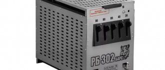
Such cores have been widely used and are used in power supplies for radio equipment since Soviet times. Therefore, finding an old transformer (for example, TC type) with a power of 200–300 W will probably not be a very difficult task. It is also very convenient for adjusting the gap that such a core is tightened with a special clamp with a screw connection (see figure below).
You can use any wire or bar (but copper is still better), the main thing is that the cross-section corresponds to the design one.
Winding and installing the choke
When disassembling an old transformer, you must very carefully remove the coils, free them from the wires and clean the junction of the core halves until shiny. The following sequence of actions looks like this:
- Place the reel on a wooden block, secure it with a vice and wrap one or two layers of keeper tape around the reel, and varnished cloth on top of it. Then carefully wind the first layer of wires, turn by turn (you will get about 8–12 turns, depending on the thickness and gaps). You must act very carefully, because the wires are hard, and the coil is made of thin and fragile getinax.
- Wrap varnished fabric over the first layer of turns, having previously coated it with varnish. The classic option is bakelite varnish, but you can use any other one, for example parquet. Wind a second layer of turns, also cover it with varnish and varnish. Carefully bend the output end.
- Do the same with the second coil, then dry both of them thoroughly. Prepare two plates of getinax (or other insulating plastic) 1–2 mm thick according to the size of the joint of the core halves.
- Place both coils on one of the core halves, place insulating pads and insert the other half. Carefully tighten the core with a clamp.
- Connect the coils in series by twisting with soldering or a screw (pre-tinned), and then insulate the connection point.
- Fix the ends of the coils intended for connection on the clamp, and then solder the terminals to them.
When checking a choke with a semi-automatic device, you need to try it in different modes, and, depending on the situation, increase or decrease the inductance by replacing the gaskets in the core gap.
In the famous book by V. Ya. Volodin “Modern do-it-yourself automatic welding machines,” a classic calculation of the number of turns in the inductor winding is given. For a home craftsman, a more simplified version of determining the number of turns would be suitable, even if their number is approximate. If anyone knows sources with such techniques or can describe how to do it themselves, please share them in the comments to the article.
Most craftsmen involved in private repairs of equipment sooner or later begin to think about how to assemble. Nowadays, equipment manufacturers offer a considerable number of such devices for use in small-scale production. This can be a device operating on alternating or direct current, a semi-automatic welding machine, or a device using electrodes. However, any good branded device costs a lot of money, and its cheaper counterpart is usually unreliable and quickly begins to fail. To assemble a welding machine, first of all you need to select or manufacture the necessary parts, this also applies to such a device as a choke.
When creating a welding machine with your own hands, you need to pay special attention to the chokes.
Power on and check
The choke for welding is connected to the system between the diode bridge and ground - a contact that connects to the material being welded. The output of the diode bridge is connected to the input of the inductor, to the output of the assembled inductor - respectively, a ground contact.
The entire assembly for welding must be tested on a piece of metal of the same chemical composition and thickness with which it is planned to carry out most of the welding work in the future. Quality indicators are:
- easy electric ignition;
- arc stability;
- relatively weak crackling sound;
- smooth combustion without strong splashes of melt.
Please note that the introduction of this element into the design of the welding machine leads not only to stabilization of operation, but also to a slight drop in current strength . If the inverter or semiautomatic device begins to cook worse, it means that the current strength has dropped.
The choke needs to be disconnected and a few turns removed from each coil. The exact number of turns in each specific case is selected empirically.
What it is?
It is quite possible to make a choke for a welding machine with your own hands. It consists of a core and two windings with a specific cross-section, designed to operate with a specific current value. A choke from a large welding equipment will not fit a small unit, and vice versa, a small model will not be effective on a large welding machine.
The choke receives and accumulates current from the step-down transformer, which facilitates smooth ignition of the electrode. During welding, the arc burns more softly and the metal of the weld pool is less splashed. If the incoming voltage is too high, the inductor takes over part of the resistance function. This allows you to more accurately tune the machine and weld thin metal.
Application
A self-made choke interacts well with transformers. Since alternating current is characterized by crackling and splashing of metal, adding this element to the circuit will allow you to cook more gently. This is especially felt when working on heating pipes, where water continues to leak from the system.
The choke for a welding inverter and semi-automatic device is also useful in facilitating rapid ignition of the arc. For example, if the inverter should produce 48 V no-load, then when the voltage in the network drops or surges, this value will be even less. When you need to weld with an MP-3 electrode, the optimal current value for which is 70 V, and at 48 V it ignites with difficulty, then in the event of a voltage drop it will be very difficult to initiate an arc. As a result, planned welding work will have to be postponed until normal voltage is restored.
The choke, in combination with a rectifier, is capable of producing a self-induction emf, which penetrates the air space and easily ignites the electrode. In the case of a semi-automatic machine, this facilitates easy start of work at the slightest approach of the wire coming from the nozzle to the product.
Combining two functions (resistance compensation and arc stabilization), this device allows you to weld thin metal under conditions of surge voltage. Thus, devices with a choke are widely used for welding car bodies at service stations, or stainless steel thin containers.
Where is the invention used?
Devices made from lamp components do not have high power ratings. The maximum threshold is up to 20 watts. Switching power supplies are used. The main area of application is the design of a network power supply of the simplest type. The step-down type is used as a matching link between the amplifier input and the signal source. There are applications where a transformer and inductor are placed between two devices and amplifiers. There are also situations when low-frequency and step-down models act as a matching element between the vehicle load and the amplifier.