Rules for working with ballast rheostats
Despite the simplicity of design and use, ballast rheostats require certain operating rules to be followed:
- Study, remember and work only if you comply with the conditions set out in the technical data sheet of the device. Don't forget to take into account climatic conditions.
- Do not work with RB in conditions of dense dust or near places where there is a lot of gas or steam, which very quickly destroys the electrical insulation in the device.
- Constantly check the device in the laboratory in accordance with GOST RD 03-614-03.
Ballast drawing and voltage graph.
If the rheostats overheat, you need to connect several rheostats to the arc - in sequential order. Well, if the welding current is less, then the resistance should be increased.
When working with aluminum, for example, the alternating current needs to be adjusted within very small limits, only up to 20%. In this case, incomplete compensation of the direct current component occurs.
If we are talking about full compensation, then you need to use devices of the UKDN or UDGU brands, which are equipped with capacitor banks.
Ballast resistance includes three types of load devices
Resistive
With its help, an appropriate load is provided on the generator and prime mover. The resistive device absorbs the energy of the entire system: the device takes energy from the generator, the generator, in turn, takes energy from the prime mover, and the engine receives energy from the burned fuel. As a result of work, additional energy is also taken: heat removed by the cooling system, exhaust losses, losses in the generator itself, as well as energy consumed by auxiliary elements. Capable of taking into account all aspects of the generator's operation. Created by converting electricity into heat. Heat is removed using air or water cooling.
Jet
It is an inductive load using iron cores. Approximately 75% of the same resistive load. Other ratios are possible in order to obtain other power values. With the help of inductive loads, complex loads that are most often found in facilities are actually simulated: lighting, heating, transformers, motors. In this case, a complete test of the entire electrical system occurs, information is collected on the reactive currents of generators and voltage regulators.
How to adjust the current when welding?
This is a fairly common question that has several solutions. There is one of the most popular ways to solve the problem; adjustment occurs through an active ballast connection at the output of the winding (secondary).
On the territory of the Russian Federation, welding for alternating current consists of a frequency of 50 Hz. A 220V network is used as a power source. And all transformers for welding have a primary and secondary winding.
Regulator for welding current
In units used in an industrial area, current regulation is carried out differently. For example, using the moving functions of the windings, as well as magnetic shunting, inductive shunting of various types.
Ballast resistance stores (active) and a rheostat are also used.
This choice of welding current cannot be called a convenient method, due to the complex design, overheating and discomfort when switching.
A more convenient way to regulate the welding current is to wind the secondary (secondary winding) by making taps, which will allow you to change the voltage when switching the number of turns.
But in this case, it will not be possible to control the voltage over a wide range. They also note certain disadvantages when adjusting from the secondary circuit.
Thus, the welding current regulator, at the initial speed, passes through itself a high-frequency current (HFC), which entails a cumbersome design. And standard secondary circuit switches do not require a load of 200 A. But in the primary winding circuit, the indicators are 5 times less.
As a result, an optimal and convenient tool was found in which adjusting the welding current does not seem so confusing - this is a thyristor.
Experts always note its simplicity, ease of use and high reliability.
The strength of the welding current depends on turning off the primary winding for specific periods of time, at each half-cycle of the voltage. At the same time, the average voltage readings will decrease.
The principle of operation of a thyristor
The regulator parts are connected both in parallel and counter to each other. They are gradually opened by current pulses, which are formed by transistors vt2 and vt1. When the device starts, both thyristors are closed, C1 and C2 are capacitors, they will be charged through resistor r7.
At the moment when the voltage of any of the capacitors reaches the avalanche breakdown voltage of the transistor, it opens, and the discharge current of the joint capacitor flows through it.
After the transistor opens, the corresponding thyristor opens and connects the load to the network.
Then the opposite half-cycle of the alternating voltage begins, which implies the closing of the thyristor, then a new cycle of recharging the capacitor follows, this time in the opposite polarity. Then the next transistor opens, but again connects the load to the network.
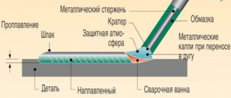
Welding with direct and alternating current
In the modern world, DC welding is used to a greater extent. This is due to the possibility of reducing the amount of filler material of the electrodes in the weld. But when welding with alternating voltage, you can achieve very high-quality welding results. Welding power sources operating with alternating voltage can be divided into several types:
- Instruments for argon arc welding. Special electrodes are used here that do not melt, making argon welding as comfortable as possible;
- Apparatus for the production of RDS by alternating electric current;
- Equipment for semi-automatic welding.
Alternating welding methods are divided into two types:
- use of non-consumable electrodes;
- piece electrodes.
There are two types of DC welding, reverse and direct polarity. In the second option, the welding current moves from negative to positive, and the heat is concentrated on the workpiece.
And the reverse concentrates attention on the end of the electrode.
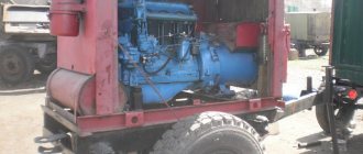
A DC welding generator consists of a motor and a current generator itself.
They are used for manual welding during installation work and in the field.
Manufacturing of the regulator
To make a control device for welding current, you will need the following components:
- Resistors;
- Wire (nichrome);
- Coil;
- design or diagram of the device;
- Switch;
- Spring made of steel;
- Cable.
Operation of the ballast connection
The ballast resistance of the control apparatus is at the level of 0.001 Ohm. It is selected through experiment. Directly to obtain resistance, resistance wires of high power are mainly used; they are used in trolleybuses or on lifts.
Such resistance is turned on permanently or in another way, so that in the future it will be possible to easily adjust the indicators.
One edge of this resistance is connected to the output of the transformer structure, the other is provided with a special clamping tool that can be thrown along the entire length of the spiral, which will allow you to select the desired voltage force.
The main part of resistors using high-power wire is produced in the form of an open spiral. It is mounted on a structure half a meter long. Thus, the spiral is also made from heating element wire.
When resistors made of a magnetic alloy are combined with a spiral or any part made of steel, in the process of passing high current, it will begin to tremble noticeably. The spiral has such dependence only until the moment it stretches.
How to make a throttle yourself?
It is quite possible to make your own throttle at home. This occurs when there is a straight coil with a sufficient number of turns of the desired cord. Inside the coil are straight metal plates from the transformer. By choosing the thickness of these plates, it is possible to select the starting reactance.
Let's look at a specific example. A choke with a coil with 400 turns and a cord with a diameter of 1.5 mm is filled with plates with a cross-section of 4.5 square centimeters. The length of the coil and wire should be the same. As a result, the 120 A transformer current will be reduced by half.
Such a choke is made with a resistance that can be changed. To carry out such an operation, it is necessary to measure the deepening of the passage of the core rod into the coil.
Without this tool, the coil will have little resistance, but if the rod is inserted into it, the resistance will increase to its maximum.
A choke that is wound with the correct cord will not overheat, but the core may experience strong vibration. This is taken into account when screeding and fastening iron plates.
Welding ballasts: rheostat for welding, how to connect the device and adjusting the secondary current
After all, what is a conductor? This is a material with minimal resistance so that electric current passes through them with the same minimal losses. This is common practice. The exception is cases with tasks “on the contrary”: when resistance needs to be increased.
This need arises when the current readings are too high and need to be regulated. It is for such purposes that a welding ballast exists. It makes welding easier and faster.
How it works?
At its core, it is a ballast rheostat - a special device for generating increased resistance for welding electricity. This rheostat is distinguished by its simplicity. It is built into many advanced and expensive models of welding machines, and can also be purchased separately.
According to the principle of its operation, the welding ballast is a point of obstacle in the path of the movement of electric current; it is a “point” of high resistance. From an external point of view, it looks like a complex thick spring.
This spring is always equipped with a movable contact, which, when moving along the spring, changes the length of the path that the current passes through the ballast.
This device cannot boast of a particular variety of models.
There are some differences, they are determined by the following criteria:
- Dimensions of the spring: the longer it is, the longer the path of electrons through all turns of the rheostat, the greater the resistance reduces the current strength.
- The nature of the metal with certain resistance coefficients.
- The thickness of the spring is also directly proportional to the resistance force. The thickness is related to the length of the rheostat.
In fact, it turns out as follows: without a ballast rheostat, the current would have a force of 250 A. If you connect a ballast to this circuit, the electric flow will begin to lose strength and would have only 10 A at the output.
Of course, the regulator can change the length of the spiral path along which the flow passes. The losses in this case would be different.
How to make a ballast with your own hands?
The first step is to find a suitable metal wire. It could be, for example, copper. Additionally, you will need a cylindrical shape, for example, a pipe and an ammeter. You need to think about what to make the moving contact from; it could be a wire.
The straight wire needs to be turned into a tight spring. To do this, it is wound onto a cylindrical shape, trying to place the turns as close to each other as possible. The end of the twisted wire must be connected to the wire for current. We also attach a moving contact.
The next step is very important: you need to check the operation of the new rheostat with help. Ammeter. The fact is that a homemade ballast for a welding machine is not as accurate as factory models.
The next caveat is that our rheostat is not equipped with a housing, so compliance with safety regulations becomes even more mandatory.
Ballast rheostat settings
The main thing in a high-quality welding process is stable performance of the electric arc, or rather, its current-voltage characteristics. Modern inverters cope well with this requirement.
Marking of ballast rheostat.
This is done by converting the current into two stages and switching the inverter itself. All other welding machines cannot boast of such characteristics. Therefore, a ballast rheostat must be present next to them.
It is designed for stepwise control of arc operation and compensation of the current component during recharge from the transformer. Nichrome wire in the parallel connection circuit is the main component element. It is important that each section of the rheostat is connected to the network independently, using a switch.
Such a rheostat has only two working functions:
- Current regulation in a discrete manner.
- Compensation of the direct current component formed during the feeding of the welding element using a transformer.
The performance and overall efficiency of a ballast rheostat directly depend on the number of turns or sections of the spiral. After all, each of them is an element of a chain that is broken using a switch.
The circuit is serial, and the connection of sections is parallel. This combination gives an excellent result: periodically connecting each of the elements to the work in order to regulate the voltage in the welding machine.
The connection of the rheostat to the welding circuit must be in series with the power source.
If there are no fans, you must ensure that several rheostats are switched on in series.
The most popular line of ballast rheostats on the market under the abbreviation RB: there are only five options for different current values - its range - minimum and maximum values.
We offer an easy walk through the most popular models to get acquainted with their technical characteristics in more detail:
RB-302
An excellent device as a companion to welding units for adjusting the current strength in semi-automatic or manual welding processes. Works in parallel with welding rectifiers and generators.
This version is designed for a power supply range of 27 - 30 V with a maximum maximum of 70 A and a minimum drop of 30 A.
The rheostat is equipped with an air cooling system. It has a good PV indicator - the on-time is 60%. This means that the welding duration should not exceed 10 minutes. Otherwise, the PV must be reduced.
In this device, the welding current adjustment is represented by six steps, which are cyclically turned on and off.
The structural elements are made of the most modern materials: the insulation, for example, is made of ceramic profiled plates, and the plateau is formed from special heat-resistant fechral wires.
RB-302U2
This model is a type of mother rheostat for operation in conditions of high humidity or harsh ultraviolet radiation. As a result, you can work with it outdoors in conditions unfavorable for conventional equipment.
RB-306
This model is more serious: it does not overheat and is much more accurate in regulating the welding power supply than the RB-302. The rheostat is equipped with an improved cooling system: there are more blind holes in the body, so the blowing of the resistors is intense and efficient.
Electrical circuit of the ballast.
All resistance elements are arranged in a modular system. This arrangement makes diagnosing and replacing elements much easier and more accurate. The range of current values is much wider, and the indicators can be adjusted with much greater accuracy.
BBR
These are special Ballast Rheostat Blocks. They are assembled from RB-306 elements for cutting metals using the electric arc method. This is an excellent solution for controlling the welding current from the rectifier in automatic machines.
Rules for working with ballast rheostats
Despite the simplicity of design and use, ballast rheostats require certain operating rules to be followed:
- Study, remember and work only if you comply with the conditions set out in the technical data sheet of the device. Don't forget to take into account climatic conditions.
- Do not work with RB in conditions of dense dust or near places where there is a lot of gas or steam, which very quickly destroys the electrical insulation in the device.
- Constantly check the device in the laboratory in accordance with GOST RD 03-614-03.
Ballast drawing and voltage graph.
If the rheostats overheat, you need to connect several rheostats to the arc - in sequential order. Well, if the welding current is less, then the resistance should be increased.
When working with aluminum, for example, the alternating current needs to be adjusted within very small limits, only up to 20%. In this case, incomplete compensation of the direct current component occurs.
If we are talking about full compensation, then you need to use devices of the UKDN or UDGU brands, which are equipped with capacitor banks.