Resistance welding has long been used in all industries. This technology is no less popular among home craftsmen. It is quite difficult to assemble a spot welding machine with your own hands, but this approach helps reduce the cost of purchasing equipment.
Where is resistance spot welding used?
The technology involves connecting workpieces or welding individual parts to metal structures without creating an electric arc.
The method is applied under the following conditions:
- At manufacturing plants. Spot welding is used in the manufacture and repair of cars, aircraft, and complex technical equipment. The method helps to create strong, durable connections that have no signs of deformation or other defects.
- At home. A self-made machine is suitable for performing simple welding operations. It will help you weld elements of a fence or pipeline, or repair a car or motorcycle.
Process technology
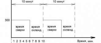
To heat the parts to the required temperature, a short-term pulse of high-power electric current is applied to them. As a rule, the pulse lasts from 0.01 to 0.1 seconds (the time is selected based on the characteristics of the metal from which the parts are made).
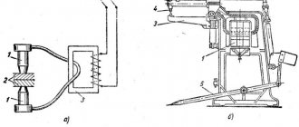
When pulsed, the metal melts and a common liquid core forms between the parts; until it hardens, the welded surfaces must be held under pressure. Due to this, as it cools, the molten core crystallizes. A drawing illustrating the welding process is shown below.
Spot welding process illustration
Designations:
- A – electrodes;
- B – parts to be welded;
- C – welding core.
Pressure on the parts is necessary so that, when pulsed, a sealing belt is formed along the perimeter of the molten metal core, preventing the melt from flowing outside the zone where welding occurs.
To provide better conditions for crystallization of the melt, the pressure on the parts is gradually removed. If it is necessary to “forge” the welding site in order to eliminate inhomogeneities inside the seam, increase the pressure (do this at the final stage).
Please note that to ensure a reliable connection, as well as the quality of the seam, it is first necessary to treat the surfaces of the parts in the places where welding will take place. This is done to remove oxide film or corrosion.
When it is necessary to ensure reliable connection of parts with a thickness of 1 to 1.5 mm, capacitor welding is used. The principle of its operation is as follows:
- the capacitor block is charged with a small electric current;
- the capacitors are discharged through the parts being connected (the pulse strength is sufficient to ensure the required welding mode).
This type of welding is used in those areas of industry where it is necessary to connect miniature and subminiature components (radio engineering, electronics, etc.).
Speaking about spot welding technology, it should be noted that it can be used to connect dissimilar metals together.
Device design and necessary parts
Any contact type welding unit consists of 2 units:
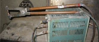
- power supply (transformer);
- clamping pliers.
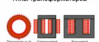
To obtain a powerful electrical discharge at a minimum voltage, an induction transformer is used.
The correct ratio of windings allows you to generate a current that is strong enough to melt the metal. The design of the pliers includes graphite or copper contacts installed on different levers that fix the mechanism.
The following types of clamps exist:
- Mechanical. Includes a powerful spring and lever. The welder's muscle force is used to compress metals. Clamps of this type are installed in household devices used for simple operations.
- Pneumatic. Installed in portable hand-held devices. Adjustable by changing the pressure in the air channel. The disadvantage is considered to be low productivity and the inability to adjust operating parameters during welding.
- Hydraulic. The clamps also have a low operating speed, but their range of settings is wider than the previous type.
- Electromagnetic. They are distinguished by the highest productivity and are installed in both manual and stationary units. Electromagnetic clamps allow you to adjust the compression force of parts during welding. This reduces the likelihood of lack of fusion and metal leaks.
Sometimes the design is complicated by adding liquid cooling systems, control of current parameters, and automatic movement of electrodes.
When assembling a homemade spot welding machine, the master will need the following parts and materials:
- a modified transformer from an old microwave oven or car battery;
- thick copper wire or cable harness of small cross-section;
- levers used to assemble clamps;
- base for installing unit blocks;
- clamps;
- wires;
- insulating materials;
- copper electrodes necessary for welding;
- control key.
We recommend reading: How to make a welding machine from a microwave
Application experience
Our experience has shown that a device assembled according to these circuits works almost flawlessly. We were pleased with the functionality and quality of the resulting seams. Of course, with the help of such a unit you will not be able to perform professional welding work, but it is not necessary. This homemade welder is suitable for pulse welding of a fence or greenhouse. In a word, it will not let any home craftsman down, and its assembly will be very cheap.
The welder assembled according to these diagrams is designed to work on a 220V network. But in our memory there have been situations when the voltage was unstable, especially in the country. Nevertheless, the arc burned stably and was ignited quite simply. Yes, this is not professional micropulse welding, but still. By the way, we recommend using only consumable electrodes when working with such a homemade device. Welding with a consumable electrode is much more effective and stabilizes the arc quite well.
Naturally, we needed to spend our own time and effort to assemble it. But the final cost of a homemade pulse welding machine turned out to be several times lower than that of budget models from the store. At the same time, the homemade device copes with its functions perfectly.
General operating principles
The algorithm for assembling the welding unit includes the following steps:
- Removing the transformer. The part is taken from an old microwave oven. It is not completely needed; to manufacture the device, a primary winding and a magnetic circuit will be required. The remaining parts are carefully removed as unnecessary.
- Formation of a new secondary winding. To do this, use a copper cable with a cross-section of at least 100 mm². Durable rubber insulation is replaced with textile insulation. To create a powerful welding machine, 2 transformers with a common winding are used.
- Installation of a control unit that ensures uninterrupted flow of the contact welding process.
- Manufacturing and connection of electrodes, the type and diameter of which are selected taking into account the properties of the metals being welded.
- Housing assembly. The main units of the device must be reliably protected from external influences. At this stage, you can use the housing from an old microwave oven or assemble the structure yourself from sheets of metal.
Pulse Welding Assembly
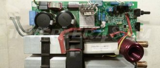
Converter
Let's start by assembling the converter. Which is also called the power part of the welding machine. Below you can see a detailed assembly diagram.
We have also provided several tables with specifications of the components used.
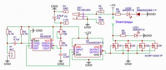
Control circuit
Below is a clear and working control diagram, and a small part of the device’s startup diagram is also visible.
As when assembling the converter, we have provided several tables with the specifications of the components used.
Pay
Below you can see a schematic image of the printed circuit board.
And here is the layout of all the elements on the board.
Please note that the “soft start” is located on the control board.
Complete device
Below you can see the assembled device. This is its simplest form. What is missing is a housing with fans, a control board (it needs to be attached to the housing itself), a connector for welding current, as well as a surge protector and a circuit breaker (also attached to the housing).
How to make electrodes
When manufacturing these elements, the following points are taken into account:
- The diameter of the electrode must correspond to the cross-section of the wire to which it is connected. Copper rods can be used as rods. Electrodes for low-power welding units are made from soldering iron tips.
- During the welding process, the electrodes wear out quickly. To restore their operating parameters, the ends are sharpened. Over time, the electrodes are replaced with new ones.
- The wire for connecting the welding rod should be short. Otherwise, part of the device's power will be lost. The current strength also decreases if there are a large number of connections in the electrode-transformer circuit.
- It is recommended to solder copper tips onto the wires to which the rods are connected. This increases the efficiency of the equipment. Since the electrodes are removable, the connection points with the tips are not soldered.
Battery device
A do-it-yourself mini-spot welding device is made using a car battery. Its power is enough to weld a contact to another one that requires restoration.
Two brass or bronze rods are attached to a block with a copper alloy terminal block; they are insulated in the area of contact with the hand. It must be taken into account that during welding the rods will become very hot; the insulator-connector should not melt.
The disadvantage of this device is the lack of a switch and high battery power. You must work with the device carefully so that there are no burns in the contact area.
How to choose an air conditioner for your home or apartmentDo-it-yourself bait - composition, application features and storage methods (115 photos and videos)
DIY sliding gates - how to build simple and automatic gates. Schemes, drawings and review of the best ideas (90 photos)
Assembling a device from a microwave oven
The device manufactured in this way allows welding with alternating current with unregulated force.
List of required tools
To create a homemade device from a microwave oven, you will need the following equipment:
- Screwdriver Set;
- sandpaper;
- copper rods;
- hammer;
- chisel;
- knife.
Conversion of microwave parts
After removing the transformer from the furnace, perform the following steps:
- Remove the secondary winding using a hacksaw or chisel. Dismantling is carried out carefully, trying not to damage the underlying layer. It is advisable to fill the space between the windings with corrugated cardboard.
- Remove the metal shunts that limit the current.
- A secondary winding is formed. At this stage, you will need a KG 1x35 wire. It can withstand prolonged exposure to high voltage and current up to 1200 A. The outer rubber insulation is removed from the cable.
- The core is covered with tape, which facilitates the sliding of the wire during winding. The cable is laid in 3 tight turns. For winding, the use of stranded soft wire is allowed. The total diameter of the cores must be at least 1 cm.
We recommend reading Description of resistance spot welding technology
After the alteration, the transformer must have an open circuit voltage of no more than 3V and a current of at least 800 A.
Homemade device diagram
Creating an electrical circuit for a welding machine is not difficult. The electrode is connected with a soft cable to the secondary winding of the transformer. The circuit includes thyristors and rectifier bridges. One end of the pressure gun is connected to the secondary winding, the other is securely fixed to the device.
The operating principle of the electrical circuit of the unit is as follows:
- Single-phase or three-phase current is supplied to the clamping mechanism.
- When the button on the gun handle is pressed, the thyristor opens.
- The capacitor is charged from the transformer. The thyristor closes, the clamping mechanism is activated. The latter operates until the capacitor discharges. Pressing the button again will generate a new impulse. The time for maintaining the charge of the capacitor is set by a variable resistor.
Assembling the device
To create the working part of the device, perform the following steps:
- Assemble the base from the bottom of the microwave oven body. One end of a metal profile or wooden beam is fixed to it. To do this, use self-tapping screws to ensure a strong fixation. A welding electrode with a cable connected to a transformer is connected to the second edge of the profile. The wire is wound around the rod, which prevents damage.
- A movable part of the apparatus is installed, which looks like a lever. A long nail is used as an axis. The side posts, created from profiles or bars, are fastened with self-tapping screws. There should be no distance between them and the base of the lever. Otherwise, the accuracy of the device’s impact is reduced.
Performance test
After all installation and assembly work, the device is checked in the following ways:
- The main operating parameters of the unit are measured. An oscilloscope is used for this. The current pulse strength should be about 800 A.
- The assembled device is used in practice. To do this, create a test seam. After completion of work, measure the temperature of the transformer. If it is too high, the circuit is not assembled correctly. When the indicator is within the normal range, 2 more test stitches are made.
What can you cook with?
The best welding option for new 18650 batteries is an industrial machine. For most users it is not available, so you have to do something of your own.
Battery
The essence of the spot welding method, as a type of resistance welding, is the rapid heating of the metal parts being connected by current passing through the joint. This releases a large amount of heat, which melts the metal at the point of contact, and compression promotes the diffusion of molten areas and the formation of a strong connection. The task is to obtain a sufficiently high current at the interface. This current can be obtained from a battery - for example, the current output of a fully charged car battery can be 700+ amperes. But the highest current depends on the transition resistance at the contact point of the welded surfaces, so it is important to pay attention to the cleanliness of the contacting faces. Also, the current limits the cross-section of the wires, so you need to take wires with a cross-section of at least 10 sq. mm. (preferably 16 sq. mm.).
Nickel tape.
First you need to prepare the tires - they are cut from nickel tape (more precisely, the tape is made of nickel-plated steel). Next you need to connect to the battery - it is better to do this using standard car clamps. Conductors of the appropriate cross-section must be connected to them. You can make special tips on the reverse side, or you don’t have to - it’s not very convenient, but there will be no additional transition resistance.
Welding the tire.
You need to cook at several points - usually at 3..5. At the end of the process, you need to check the quality of the connection - pull it with your hand. The shank should not come off.
Welded nickel strip.
Transformer device
If you don’t have a battery at hand, you can make a welding machine from a step-down transformer. A transformer with an overall power of 150..200 W is suitable. This means that the cross-section of the central rod of the core should be 17...20 sq.mm. It is necessary to remove the secondary winding and wind another - 2..3 (possibly 4) turns with a wire of the appropriate cross-section. On the Internet you can find advice on winding the secondary with a cable from a welding machine, but to weld busbars to batteries, a conductor with a cross-section (not thickness!) of 10..16 mm is enough .
Transformers from faulty microwave ovens are good for this purpose, and they can be bought for the price of scrap. First of all, you need to remove the secondary high-voltage winding and knock out the shunts (they take up space, which is already small, and somewhat reduce the power of the transformer).
Transformer from a microwave oven with the secondary winding removed and shunts knocked out.
At least three turns of wire must be laid in the vacant space. If you take a conductor with a cross-section of 16 sq. mm, you can try and lay 4 turns.
Laying the secondary winding.
The brought out ends of the winding can be equipped with lugs. They must be secured by crimping, not soldering - when heated, the solder may flow.
Secondary winding terminals with cable lugs.
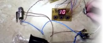
To control the current and pulse duration, you will need a NY-D01 module, and to power it, a small transformer with an output voltage of 9..12 VAC. All this must be connected according to the diagram attached to the board and hidden in a suitable housing.
NY-D01 controller board.
After final assembly, you can try out the device. Welding parameters may need to be adjusted to obtain optimal results.
Welding tires using a homemade machine.
The design of the transformer from the microwave oven is such that it heats up noticeably even at idle. You cannot keep the primary winding under mains voltage for more than half an hour.
Homemade capacitors
If there is no transformer of sufficient power, you can try using a battery of oxide capacitors. A capacitor has the property of storing energy for a relatively long time and then releasing it almost instantly. You can assemble a battery of sufficient capacity from oxides, charge it from any available voltage source, and discharge it onto the contacts of the welding device.
Operating principle of a capacitor-based welding device.
Resistance R depends on the highest current source. It can be calculated using the formula R=U/Imax , where:
- U – source voltage;
- Imax – the highest output current.
So, if there is a 12-volt source with the highest current of half an ampere, then the resistor should be 24 Ohms and its power should be U*I=6 watts. You can install a resistor with a lower power - calculations show that a 100,000 uF battery will be fully charged in 12 seconds, and the highest current will flow only at the first moment, then it drops according to an exponential law. Even a lower power resistor will not have time to burn out .
The initial current depends on the voltage to which the capacitors are charged, and the duration of the discharge current (and, therefore, the energy transferred to the welding site) depends on the battery capacity. It is chosen according to necessity - how massive the parts to be welded will be, how difficult it is to warm them up.
Capacitors must be able to withstand the operating voltage with a reserve. So, for a 12-volt source it is necessary to use capacitors of at least 16 volts.
Contactor from a welding transformer
Such equipment can be turned into a full-fledged resistance welding tool. The only drawback is the inability to control the current strength.
Drawing development
The correct choice of circuit helps to produce a working welding machine. Preference is given to simple drawings that include a minimum number of parts and blocks. Such options do not allow you to create an overly powerful device, but the device is sufficient to perform minor repairs on a car, garden equipment, and fences.
We recommend reading Description of resistance spot welding technology
List of parts and consumables
To convert a welding transformer into resistance welding equipment, you will need the following elements and materials:
- a transformer that converts electrical energy;
- thick cable;
- copper electrodes;
- bolts;
- tips;
- breaker;
- wooden blocks, plywood to create the body.
The process of creating a device
The homemade device is assembled as follows:
- The welding transformer is installed in a housing made of metal sheets. The electrical board is assembled on a textolite sheet more than 1 cm thick. The part is fixed in the body of the welding machine.
- A welding wire is bolted to the busbar and secondary winding. The remaining end of the cable is connected to the electrode.
- The power wire is connected to the contact block located on the electrical board.
Spot Welding Operation
A master using a contact transformer apparatus must stand on a rubber mat and use protective gloves and goggles. The grounding cable is connected to the part to which another workpiece will be welded. After this, press the power key, compare the elements to be connected, and clamp with the electrode of the welding gun.
5 seconds after the start of the impact, the rod is transferred to the next point.
Equipment
Ready-made machines for spot welding are either stationary or portable; they are convenient to use when carrying out repair work. Automatic welding machines are used in industry. There are portable lever welding devices called tongs.
Welding equipment is expensive, and you rarely need to use it. Craftsmen found a rational way out of the situation.
It is quite possible to make a spot welding device for batteries and a body yourself. It can be used to repair household appliances and create decorative metal products.
DIY resistance welding pliers
To make such a device yourself, follow these steps:
- Form the basis. For this purpose, available materials are used - steel sheets up to 5 mm thick. Strips 2 cm wide are cut from them. The length depends on the design of the welding tongs. The strips can be replaced with metal rods. The ends of the two blanks are bent in the form of tongs.
- Place the parts on top of each other and join them together. A hole is drilled in the central part where the adjusting screw will be located. A dielectric layer is placed between the plates.
- A hole is drilled at one end of the rod or strip to secure the copper cable. The same actions are performed for the second workpiece. The holes should be opposite each other.
- The metal elements of the pliers are covered with a rubber pad and electrical tape. The materials will protect the welder from electric shock during work.
- Install the spring between the handles of the pliers. The part is necessary for fixing the elements to be welded.
Secondary winding
Selecting parameters
DIY laboratory power supply
When remaking a CT, the main attention should be paid to the parameters of the secondary winding, which determine the output characteristics of the device (its load current, in particular). In this case, it is important to select a bus cross-section that would provide a current density of about 8 A/mm² (with a cross-sectional area of about 120 mm²). Since it is very difficult to handle such a thick busbar when winding on a torus, they are most often limited to a value of 80 mm².
Note! The specified cross-section can be obtained by putting together several wires of slightly less thickness.
To facilitate the conditions for converting a CT into a point unit, it is advisable to pre-calculate the amount of wire required for rewinding it. After this, it will be possible (based on the space occupied by the winding) to decide whether it will fit into the free space remaining on the torus or not.
Important! In the case where the new winding does not fit into the torus, the old secondary coil will have to be completely disassembled (dismantled).
To make it easier to handle new wires during the winding process, it is recommended to wrap them with fabric-based insulating tape. To determine the exact number of turns that affect the output voltage, we recommend using the test winding method with a small-section wire in insulation.
Since the winding in this case is not connected to the load, the cross-section of the test wire is not very important. Experience has shown that during rough tests it is sufficient to use no more than 10 turns. After winding them, the transformer should be connected to the network and the voltage produced by the test coil should be measured, after which it is divided by the number of turns. The result is a figure indicating the number of turns required to produce one volt of output.
Since in this case it is necessary to obtain 6 Volts, multiplying the number obtained from the test connection by 6, we obtain the required number of turns.
In order to make a new device with your own hands, you must first calculate the amount of wire required for rewinding the CT. After this, it will be possible (based on the space occupied by the bus winding) to determine whether it will fit into the free space remaining on the torus.
Winding diagrams and placement
The connection diagram and the order of placement of the “secondary” depend on the type of core selected. Given the toroidal base of the CT that we have declared, it is more convenient to divide it into two half windings connected in series (3 Volts each).
In order to increase the load capacity (increase the welding current), you can make two windings of 6 Volts each and connect them in parallel. In this case, the output voltage will not change, and the load current can be doubled. This design option allows us to solve the problem of the large cross-section of the secondary bus, which can then be reduced by half.
Various types of connections of such windings are shown in the picture below.
Secondary connection circuits
The order in which they are connected is very important to obtain the required output parameters, and mistakes made in this case can lead to completely different indicators. So, in particular, if you make a mistake during installation and turn on two windings in opposite directions, as a result they will be short-circuited to one another and will produce zero voltage at the output, which is equivalent to a short circuit.
At the ends of ready-made secondary windings, special tips should be equipped by crimping.
Using spot welding on lithium batteries
Using a battery to weld a nickel plate to the battery is the easiest way. To assemble the mini-unit you will need a battery, a charging cable, a piece of single-core wire, and electrical tape. 2 electrodes are created from the core, the ends of which are stripped and secured. The distance between elements should be 3 mm.
A charging cable connected to the terminals of the lithium-ion battery is connected to the other ends of the electrodes. Place the nickel plate on the battery and press the energized electrodes against it. As a result of a short circuit, the metal melts.
general information
Resistance welding (also "electric resistance welding", "electric resistance welding" or "ERW") is a method of joining metals by heating them with current and simultaneously mechanically deforming them with pressure. In simple terms, a weld is created by heating the metal and then compressing it under two thick metal electrodes. When resistance welding, it is the current, not the pressure, that plays the key role. Below is a diagram of the simplest resistance welding.
During the passage of current during welding, heat spreads through the metal part, in the weld area, and also between the metal electrodes. In this case, all these elements are heated at different temperatures; the highest concentration of heat is observed when contact is established between the electrodes and the part.
If the device is configured correctly and the welding technology is followed, then the metal surface should not heat up too much, since in resistance welding it is not so much the high melting temperature that is important, but the combination of temperature and mechanical action. In addition, the electrodes must be cooled (for example, with water). So it is important to monitor the heating temperature. If it is excessive, then this is the first sign of a welder error or faulty equipment.