A horizontal boring machine, the models and technical characteristics of which may vary, has the following purpose:
- Boring holes.
- Drilling.
- Turning parts with a cylindrical shape.
- Processing of product ends.
- Milling.
- Countersinking.
- Thread cutting using a product designated 2620V.
And this is not a complete list of operations performed by the installation of a horizontal boring machine. Thanks to this, it is possible to use only one type of equipment to carry out a full cycle of manufacturing parts from blanks. For multi-batch production, this is a very convenient option; no additional equipment is required.
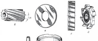
The presence of a spindle is one of the distinctive features. This part of the structure can be horizontal or vertical. 1 horizontally located element is most common.
The spindle is used to hold cutting action attachments on the 2620 horizontal boring machine, including:
- countersink;
- drill;
- incisors;
- cutters and so on.
During operation, the parameters are determined by the diameter of the spindles. The same applies to the overall dimensions of the machines, including the 2620V version.
About the design features
The design features and the workpieces used make it possible to distinguish the installation for a special, universal purpose.
Horizontal boring machines 2620 are:
- Diamond boring machines.
- Jig boring machines.
- Horizontal view.
The horizontal machine has three versions:
- with two directions of movement;
- with movement in one direction;
- lack of movement.
The spindle is moving, which means that work is starting, shaping is taking place, when workpieces are processed using a horizontal boring machine 2620. Both the tool itself and the workpiece can be fed. The specific option is determined by the technology used. Processing is not complete without additional movements:
- Using guides when moving the steady rest.
- Connection between the rest and the rear pillar.
- Movement of the table across or along.
- Spindle head running vertically. 2620V designs also have this option. This makes the technical characteristics high, and relative to the 2620a option.
Most of the machines are equipped with a rotary table, with spindles of 125 mm diameter. The tables move both transversely and lengthwise. Among the important additions are the A-pillars, which have no movement.
With a 125 mm spindle diameter, the racks move without problems in one or several directions. But most often there are models of horizontal boring machines 2620 with stationary components.
The work - what principle is it based on?
Feed movements are the main operating feature of these devices. Several important elements and principles need to be described here:
- Fastening of cutting tools occurs with the participation of a faceplate support or spindle. This is where the rotation begins. The principle continues in the 2620a models.
- Placement on the surface of a movable table, using a special device.
- When working, the table moves, lengthwise or crosswise. 2620V models have the same capabilities.
The front post is involved in the movement of the spindle head, while maintaining the vertical direction. The support steady rest is combined with the stand at the rear. The movement of two parts occurs simultaneously.
When holes are bored or internal threads are cut, a translational movement is carried out by a boring spindle. When a part is processed using a 2620 horizontal boring machine, the faceplate with the caliper moves only in the radial direction.
Design of radial drilling machines
Each radial drilling group machine consists of:
- hard base,
- cylindrical columns (internal and external),
- traverses (trunk),
- drill head (spindle head),
- electrical and hydraulic control equipment.
Main components 1 Base 2 pedestal 3 hydraulic pump motor 4 column 5 arm lifting/lowering tank and column clamp 6 spindle motor 7 arm lifting/lowering motor 8 arm lifting/lowering screw 9 Spindle head 10 arm
Kinematics
The main movements during drilling operations are the rotation and movement of the machine spindle quill. The kinematic chains that perform these movements are equipped with controls that allow the tool to be set to the required rotation speed and feed.
- rotation of the movable column of a radial drilling machine,
- vertical movement of the console (traverse),
- fixing the traverse on the column at operating height,
- fixing the spindle head on the traverse,
- switching spindle speeds and quill feeds.
When processing parts on radial drilling machines, the coordinates of the center of the hole and the axis of the tool are combined by moving the drilling head relative to the stationary workpiece in the polar coordinate system. This system is characterized by two parameters: the angle of rotation of the traverse and the radius of the position of the spindle head on it.
Machining holes at an angle is only possible when the workpiece itself is installed at an angle using special equipment and devices.
Radial drilling machine Z30132
Stand with work table
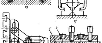
The machine bed, combined with the working base (table), is usually cast from gray cast iron. It is designed to fix the entire machine on the foundation, install the column base with the traverse and the spindle head, as well as fasten the equipment and parts using the T-shaped grooves of the working base.
A workpiece of small dimensions can be installed on an attached box-shaped table, or directly fixed on a specially treated surface of the base (work table). Fastening the workpiece outside the working surface of the table is rarely used, because introduces an additional error into the processing accuracy of the product.
Rotary column
The column is mounted vertically on the machine bed and rotates around its axis relative to a fixed internal stand on roller bearings. The traverse is fixed to the column.
A mechanism for raising/lowering the traverse, driven by an electric motor, is mounted in the upper part of the column.
Traverse (console)
The console (arm or trunk) of the radial drilling machine is mounted directly on the column; it has a separate electric drive, moves up and down, and also rotates around a vertical axis together with the support column. Rotation, depending on the machine model, can occur either manually or using an electric drive.
A drill head with a working spindle is installed on the guides of the cantilever traverse. The traverse can be lowered or raised according to the height of the workpiece. Electrical equipment and hydraulic elements are mounted in a niche located on the reverse side of the sleeve.
Spindle head
The drill head (spindle head), mounted on a traverse, is structurally a separate power unit, having feed boxes, speed boxes, as well as mechanisms for setting the drilling depth.
In radial drilling machines, the spindle serves to fix the processing tool and transmit torque and linear feed to it.
The tool is inserted into the inner cone of the quill (Morse taper No. 4-6 or metric taper, depending on the model), and then coordinately oriented relative to the workpiece by rotating the console and moving the spindle head along it.
For operator convenience, all machine controls are located on the drilling head:
- multifunctional steering wheel for moving the spindle headstock and spindle quill;
- buttons for controlling the clamping/unclamping of units, turning on/off spindle rotation, emergency stop, turning on the work area lighting;
- handles for selecting rotation speed, spindle feed, direction of spindle rotation, switching between manual and automatic feed.
| Radial drilling machine z3050 |
The feed box is located between the spindle and the spindle motor; Rotation from the electric motor is transmitted through gears and friction couplings. The friction clutch allows you to quickly reverse when cutting threads, cut off the feed when the required drilling depth is reached, and protect the gearbox from overloads.
The head can move along the console guides manually. It is fixed in the desired position before performing the drilling operation using a special clamping mechanism controlled by a separate button.
Since the spindle is mounted in a retractable quill, it allows holes of varying depths to be drilled without moving the yoke.
Fixation of the rotary column, as well as clamping/unclamping of the spindle head on the traverse guides, occurs using hydraulic mechanisms controlled by remote control buttons.
Coolant system
The coolant tank and the pump unit for supplying coolant to the tool are also located in the technological cavities at the rear of the machine. The switch is located in the base of the column. The coolant drains back by gravity.
Model 2620 Features
This CNC horizontal boring machine also has a number of modifications - 2620G, 2620V, 2620A, 2A620, 2620. When using them, it was previously possible to process parts with bodies of medium or larger sizes. Machines are not produced without retractable spindles.
It is characterized by the presence of faceplates inside, 90 mm in diameter. Parts weighing less than 3 tons are processed. This is confirmed by the passport is2a636f1.
The differences between the models are as follows:
- 2a620G – no rear pillar;
- 2А620В – rear pillar present;
- 2a620F1 – with a device that provides digital identification.
Information about modifications 2A622F4 and 2A622
This is a new type of CNC horizontal boring machine, replacing obsolete analogues.
The devices are designed to process parts in a cantilever manner, even with large-sized housings. Their weight can reach up to 4 tons. Processing should not be a hassle, even if there are holes that require precise parameters. And when certain dimensions are saved for connecting the axes. Sometimes products with the number 2L614 are designed this way.
An obligatory part of the equipment is a rotary table and a front stand that maintains a fixed position. But the table itself moves, lengthwise or crosswise. On machines of this series it is easy to mill workpieces following an octagonal contour. Let's assume an option with a circular table feed. One of the available modifications is is2a636f1.
The design also includes a retractable spindle with a diameter of 110 millimeters. The plates are mounted in one position on the spindle headstock, at the end of the wall. This is how the horizontal boring machine model 2a614 works.
Among the main characteristics it is worth noting high rigidity and the ability to resist vibrations. Due to this, the service life of the spindle device is increased. Console technology increases efficiency. Machining the end surfaces of parts is made possible thanks to a removable faceplate. Boring large diameter holes is simplified. The 2L614 variants have this property.
The type of design determines the presence of certain additional parts:
- CNC option.
- Digital identification technologies.
- Coordinate readings are in digital form, this is important for the processed part.
2a614 - how is the model different?
The main purpose of the model with the designation 2a614 is case-type parts, weighing up to 2 tons. It simplifies the work with structures where there are holes of precise dimensions with connections that require compliance with the parameters between the axes. Boring machines of the 2A614 series are universal devices that provide access to the following capabilities, just like the 2L614 products:
- Machining grooves of a ring device.
- Grinding the surface at the ends.
- Work with sampling, milling.
- Reamed holes.
- Countersinking.
- Boring holes. Horizontal boring machines 2a622 also cope with this function.
- Drilling.
The manufacturer can additionally install a thread-cutting device if necessary. Even for the 2L614 design.
A mandatory addition is the clamping of tools using a mechanized method. The device is characterized by high resistance to vibration influences. The level of productivity is so high and the controls are so convenient that work requires a minimum of effort and investment. The level of accuracy will also be pleasantly surprising. But horizontal boring machines 2a622 can also boast of this.
A table with a turn can be built into any design. It moves along and across the spindle part. Characteristically, there are pillars in front that do not change position. Like the model 2L614.
The work is also carried out due to the built-in faceplate, with a radial support. The spindle and faceplate would not be able to move without the participation of an alternating current electric motor. For this, a high-speed box with a gear device is used. The gear selector mechanism also becomes an indispensable assistant.
The DC motor is responsible for organizing the feed. The breadth of the regulatory spectrum is sufficient to ensure that resolving the issue does not cause additional problems. The feed amount can be changed at any time without stopping the movement. This opportunity is also provided in models of horizontal boring machines 2m614.
Purpose of the machines
Devices can be used when:
- There is a need for thread cutting (both internal and external);
- Drill blind and through holes;
- Countersinking is carried out;
- The ends of the workpieces are trimmed;
- It is necessary to do face and cylindrical milling.
In most cases, such equipment is used for finishing or semi-finishing. Part bodies are processed extremely rarely, but sometimes such manipulation is carried out. Boring machines are repaired in approximately the same way as lathes. This also applies to operating conditions and rules, because the machines have a similar design.
Like other numerous special types of equipment, the boring machine was designed on the basis of a lathe.
2L614 – about equipment characteristics
This machine also represents a group with universal products. It is used when processing body parts weighing no more than 1000 kilograms. Other features are also characteristic:
- Equipped with a built-in rotary table. Standard movements - using longitudinal, transverse directions. They are also followed in product 2a622f4.
- It is worth noting the presence of a front pillar, which is motionless.
- Among the main units is an alternating current electric motor, which is responsible for organizing the rotational movement, which is carried out with the participation of the spindle and faceplate.
- It is easier to control the process when using a gear selection mechanism with a handle. As in option 2a622f4.
The 2l614 modification machine is always supplemented not only with a built-in type of faceplate, but also with a radially moving caliper. The list of operations performed is larger thanks to the radial caliper.
When machining, you can use the so-called retractable spindle. Then milling work makes it possible not to use a radial type caliper.
The machines will benefit enterprises in the field of mechanics and tool production. In terms of accuracy, there is correspondence to the category designated H. Products 2a622F4 are designed differently.
Video: CNC horizontal boring machine.
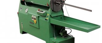
Horizontal boring machine 2620VF1, 2A620
Machine after major overhaul 12 month warranty
2620, 2620A, 2622, 2622A horizontal boring machines. Purpose and scope
Machines models 2620, 2620A, 2622 and 2622A (general size) are designed for processing body parts with precise holes connected by precise distances.
The largest weight of the workpiece (with a uniformly distributed load on the machine table) is 2000 kg.
Models 2620 and 2620A have a radial support on an integrated faceplate and a normal retractable spindle with a diameter of 90 mm and are more versatile. They are primarily intended for work that requires the use of a radial support when turning end surfaces and when cantilever boring large diameter holes.
Machines models 2622 and 2622A have a reinforced retractable spindle with a diameter of 110 mm without a radial support, are characterized by increased rigidity and vibration resistance of the spindle system and have an advantage over other machines in work that does not require the use of a radial support.
Depending on the requirements for reading and setting by coordinates, the machines have two versions;
- with optical device
- with precision electric stop mechanism
Machines models 2620 and 2622 have optical screens (division value 0.01 mm) and are primarily intended for work in mechanical and tool shops when it is necessary to obtain increased coordinate accuracy.
Machines models 2620A and 2622A have a vernier scale (scale - vernier) (graduation value 0.05 mm) and a precision electric stop mechanism are intended for wide use in machine shops.
The electric stopping mechanism makes it possible to re-set coordinates along the stops with an accuracy of up to 0.05 mm, which in a significant number of cases eliminates the need to use expensive jigs when processing batches of repeating parts.
Compared to previously produced models, the model 2620 machine has the following features:
- To increase rigidity and accuracy, the machine has mechanisms for clamping the rotary table, rear rack, rest, upper transverse table slide, lower longitudinal table slide on the bed guides, spindle head on the front rack guides and boring spindle on the tail guides of the spindle head.
- A stepless change in feed rates is applied.
- There is a separate electric motor that can be used to quickly rotate the table.
- A single-handle selective mechanism with a pulse device is used to switch 20 speeds of rotation of the spindle and faceplate with a handle.
- There is a blocking of the selective speed switching mechanism with an electric variator 19 to change the speed of minute feeds, as a result of which the feeds for each revolution of the spindle (or faceplate) remain unchanged when their rotation speeds change.
- Special mechanical and electrical locking devices are used to protect the machine from incorrect activation.
- There is an automatic shutdown of feeds at the extreme positions of the table and spindle head.
Modifications of horizontal boring machine 2620
2620A, 2620E, 2620D, 2A620-1, 2A620F1, 2A620F11, 2A620F2, 2A620F2-1 - horizontal boring machines manufactured by the machine tool industry
2620V, 2620G, 2620VF1, 2620VF11, 2620GF1 - horizontal boring machines produced by the Ivanovo Heavy Machine Tool Plant IZTS
2A620-2, 2A620F1-2, 2A620F20-2 - horizontal boring machines manufactured by Charentsavan Machine Tool Plant
Technical characteristics of horizontal boring machines 2620, 2620B
| Parameter name | 2620 | 2620V |
| Basic machine parameters | ||
| Diameter of retractable boring spindle, mm | 90 | 90 |
| Largest diameter of spindle boring, mm | 320 | |
| The largest diameter of bore by the faceplate support, mm | 600 | |
| Maximum length of boring and turning of the faceplate with a caliper, mm | 550 | |
| The largest diameter of the drill (along the cone), mm | 65 | |
| Table | ||
| Working surface of the table, mm | 900 x 1120 | 1120 x 1250 |
| Maximum mass of the processed product, kg | 2000 | 3000 |
| Maximum table movement, mm | 1000 x 1150 | 1000 x 1120 |
| Limits of table working feeds (lengthwise and crosswise), mm/min | 1,4…1110 | 1,4…1110 |
| Maximum table feed gain (lengthwise and crosswise), kgf | 2000 | 2000 |
| Dial scale division, mm | 0,025 | |
| Table rotation dial scale division, degrees | 0,5 | 1 |
| Switching stops | There is | |
| Speed of fast movements, m/min | 2,2 | |
| Speed of fast installation circular movements, rpm | 2,8 | |
| Spindle | ||
| Maximum horizontal (axial) movement of the spindle, mm | 710 | 710 |
| Spindle speed, rpm | 12,5…2000 | 12,5…1600 |
| Number of spindle speeds | 23 | 22 |
| Limits of spindle working feeds, mm/min | 2,2…1760 | 2,2…1760 |
| Limits of working feeds of the radial caliper, mm/min | 0,88…700 | 0,88…700 |
| Limits of spindle head working feeds, mm/min | 1,4…1110 | 1,4…1110 |
| Maximum vertical movement of the spindle head (installation), mm | 1000 | 1000 |
| Speed of rapid movements of the spindle head, m/min | 2,2 | |
| Speed of rapid spindle movements, m/min | 3,48 | |
| Faceplate rotation speed, rpm | 8…200 | 8…200 |
| Number of faceplate speeds | 15 | 15 |
| Ability to disable faceplate rotation | There is | |
| Possibility of simultaneous feed of support and spindle | There is | |
| Maximum movement of the radial support of the faceplate, mm | 170 | 160 |
| Speed of rapid movements of the radial support, m/min | 1,39 | |
| Maximum torque on the spindle, kgf*m | 495 | 140 |
| Maximum torque on the faceplate, kgf*m | 780 | 250 |
| Maximum spindle feed gain, kgf | 1500 | |
| Maximum caliper feed gain, kgf | 700 | |
| Maximum headstock feed gain, kgf | 2000 | 2000 |
| Cutable metric thread, mm | 1…10 | 1…10 |
| Cutable inch thread, number of threads per 1″ | 4…20 | 4…20 |
| Drive unit | ||
| Number of electric motors on the machine | ||
| Main motion drive electric motor Power, kW | 10 | 10 |
| Main motion drive electric motor, rpm | 3000 | 2890 |
| Feed drive electric motor, kW | 1,52 | 2,1 |
| Table rotation drive, kW | 1,7 | 2,0 |
| Dimensions and weight of the machine | ||
| Dimensions of the machine, including travel of the table and slide, mm | 5510 x 3200 x 3012 | 5700 x 3400 x 3000 |
| Machine weight, kg | 12000 | 12500 |
Dimensions of the working space of the horizontal boring machine 2620, 2620A
Arrangement of components of horizontal boring machine 2620, 2620A, 2622, 2622A
The general view and layout of the machine is shown in Fig. 32.
The main components of the machine are: bed 28, front stand 21, spindle head 22, table 10, rear stand 5 with steady rest 3, faceplate 13, radial support 14, cabinet 24 with electrical equipment, electric machine unit 25.
The parts to be processed are mounted on a rotary table 8.
The machining tool is placed either on mandrels fixed in the inner cone of the spindle 15, or on a tool holder mounted on the radial support 14. The tool intended for processing long holes is installed in long mandrels (boring bars), the right side of which is fixed in the inner cone of the spindle 15, and the left one rotates (and can simultaneously move in the axial direction) in the liners of the steady rest 3.
The machine spindle moves to a given coordinate using the following two adjustment movements:
- movement of the transverse slide 7 and the workpiece in the transverse (horizontal) direction. This displacement value is measured roughly (with an accuracy of 0.05 mm) using a ruler with a vernier 11 and more accurately (with an accuracy of 0.01 mm) using an optical screen 9;
- vertical movement of the spindle head 22 and the processing tool. This displacement value is measured roughly (with an accuracy of 0.05 mm) using a ruler 18 and a vernier 17 and accurately (with an accuracy of 0.01 mm) using an optical screen 16.
When working on horizontal boring machines, the following types of feeds are used:
- for processing cylindrical holes - axial feed of the spindle, and sometimes longitudinal feed of the table;
- for milling the end surfaces of parts - by transverse feed of the table or vertical feed of the spindle head;
- for processing the end surfaces of parts with a cutter, turning grooves or boring chambers in holes - by radial feed of the caliper;
- for cutting threads with a cutter - the axial feed of the spindle is equal to the pitch of the thread being cut.
Location of controls for horizontal boring machine 2620, 2620A
List of controls for horizontal boring machine 2620, 2620A
- Start, reverse and stop spindle rotation
- Spindle jog
- Single-handle selective gear shifting
- Turning the faceplate on and off
- Starting and stopping the electrical unit
- Start and stop feed
- Selecting the feed amount with an electric variator
- Starting fast movements
- Starting installation movements
- Installation for transverse movement of the table and vertical movement of the spindle head
- Installation for longitudinal movement of the table
- Moving the spindle head by hand
- Longitudinal movement of the table by hand
- Lateral movement of the table by hand
- Installation rotation of the table by hand
- Adjusting the position of the steady rest
- Moving the rear pillar by hand
- Moving the spindle by hand and setting the spindle to feed
- Moving the faceplate radial support by hand and setting it to feed
- Quick installation rotation of the table
- Spindle clamp
- Faceplate Radial Caliper Clamp
- Headstock Clamp
- Table cross sled clamp
- Table sled clamp
- Turntable Clamp
- Rear pillar clamp
- Steady rest clamp
- Steady Rest Bushing Clamp
- Portable remote control. Duplicates movements 121; 122; 126; 128; 129
Kinematic diagram of horizontal boring machine 2620, 2620A, 2622, 2622A
Kinematic chain of the main movement drive. Since the cutting tool can be mounted on mandrels that are mounted in the spindle cone, and on the faceplate support, rotation can be imparted to both the spindle and the faceplate. In both cases, the two-speed electric motor M1, controlled from the remote control 11, through a kinematic chain with two three-crown blocks B1 and B2 rotates shaft IV with 18 frequency steps.
Spindle rotation VI. From shaft IV, through a two-stage gear transmission switched by coupling Mf1, rotation is transmitted to shaft V and spindle VI. The spindle VI can move axially inside the hollow shaft V.
Design and operating characteristics of the main components of the machine
The bed 28 (Fig. 32) is used to attach the machine to the foundation and to move the table 10 and the rear rack 5 along its guides. The bed has a box-shaped cross-section with internal stiffeners. A flanged DC electric motor is mounted on the right side of the frame to carry out feeds and accelerated idle runs of the working parts of the machine.
The front post 21 is rigidly fixed on the right extended side of the frame. The front post has vertical guides for moving the spindle head 22,
The mass of the spindle head is balanced by a load connected to it by a cable thrown over two blocks.
The spindle headstock 22 has the shape of a closed box, to which the following components are attached and located: the electric motor of the main movement drive, the gearbox, the spindle block, the tail part 23 of the spindle headstock, the faceplate 13 with a radial support 14, handles and machine control mechanisms.
The boring spindle is clamped against axial movements by handle 26, and the spindle headstock by handle 27.
The table 10 of the machine is used to install and move the workpiece and consists of three main parts: a longitudinal slide 6, a transverse slide 7 and a rotary table 8.
The longitudinal slide 6 can move along the guides of the frame 28 in the longitudinal direction or be rigidly fixed to these guides by a clamping device. To accurately measure the longitudinal movements of the table, use a ruler and vernier 29, which allows you to measure movements with an accuracy of 0.05 mm.
The transverse slide 7 can move along the guides of the longitudinal slide in the transverse direction or be rigidly fixed to these guides.
The transverse slide is moved by manually rotating the shank 31. The counting is carried out along a dial with a division value of 0.025 mm.
The rotary table 8 can be rotated along the ring guides of the transverse slide. On the surface of the table there are seven T-shaped slots for the heads of bolts that secure the workpieces. The middle groove is made calibrated in width in order to use stops to adjust the exact rotation of the table by 90, 180, 270 and 360°. Intermediate table positions are set with an accuracy of 0.5° on a circular scale.
After turning, the top of the table is clamped in the desired position.
The rear stand 5 with steady rest 3 serves to support the left end of the boring bars. The right end of the boring bars is inserted into the cone of the boring spindle 15. The rear stand can be moved along the frame guides 28 by rotating the square shank 1 with a removable handle. The rear stand is rigidly fixed in the desired position on the bed guides.
The steady rest 3 can move along the vertical guides of the rear pillar. The steady rest moves up or down simultaneously with the movement of the spindle head 22.
To ensure precise alignment of the steady rest bearing and the machine spindle, you can use an adjustment device, which is driven by flywheel 2.
To measure the vertical position of the steady rest axis, the rear post has a ruler with a vernier 4, which allows the reading to be carried out with an accuracy of 0.05 mm.
The steady rest has a hinged part that makes it easy to replace the hardened steel bushings. The inner diameter of these bushings is selected according to the outer diameter of the boring bar being installed. The hinged part clamps the bushings.
The faceplate 13 communicates the cutting movement to the tools mounted on the radial support 14.
Radial support 14 is designed for installing cutters operating with transverse feed for turning end surfaces on workpieces. The caliper rotates together with the faceplate and at the same time can perform radial feed.
Cabinet 24 houses the electrical equipment of the machine. The electric machine unit 25 is designed to generate the direct current necessary to power the electric motor. The unit consists of a three-phase alternating current electric motor driving a direct current generator.
The remote control 12 is used to control all the electric motors of the machine, except for the table rotation electric motor, which is controlled by the station buttons 30. The machine has a portable remote control 32 with the same buttons as on the remote control 12.