Models of broaching machines differ in several ways:
- purpose - internal or external broaching;
- universality - general and highly specialized purpose;
- direction of working movement - horizontal or vertical;
- the nature of the working movement - circular, broaching movement, workpiece movement;
- number of carriages - one or several;
- position - conventional machines (single-position), with rotary tables (multi-position);
- availability of CNC.
Domestic horizontal broaching machine
The main types are:
- horizontal broaching machine (for internal processing of holes);
- vertical broaching machine (for internal and external broaching);
- CNC centers that have devices for automatic installation/removal of workpieces and tool change.
Performance characteristics include such indicators as traction force - from 50 to 1000 kN, and drawing stroke length - from 1000 to 2000 mm.
1.1 Horizontal broaching machines
They are used for processing the internal and external surfaces of parts in the linear direction using broaches that have different profiles.
When working, only the linear movement of the tool (broach) or workpiece (part) in the horizontal direction is used. Sampling (cutting) of material occurs due to the uniform lifting of the teeth on the broach along its entire length. The work process can be automated by installing CNC systems.
1.2 Process of operation of the horizontal broaching machine SGP12 (video)
1.3 Vertical broaching machines
The operating principle of a vertical broaching machine is the same as that of the horizontal version, but there are several advantages:
- the broaching axis does not sag or bend;
- when upgrading to increase productivity, it is easier to install additional broaches;
- small occupied production area, since the working movement occurs vertically.
Cross planing machines
Let's consider the technical characteristics and design features of the cross-planing machine mod. 7E35, designed for processing flat and shaped surfaces on small workpieces in single or small-scale production conditions, for example in tool and repair shops.
Technical characteristics of the machine mod. 7E35
Maximum stroke length of the slider, mm……………………..520
Number of double strokes of the slider in 1 minute………………………… 13.2; 19; 26.5; 37.5; 53; 75; 106; 150
Horizontal table feeds in one double stroke
slider, mm………..0.2; 0.4; 0.6; 0.8; 1.0; 1.2; 1.4; 1.6; 1.8; 2.0; 2.2; 2.4; 2.6; 2.8; 3.0; 3.2; 3.4; 3.6; 3.8; 4.0
Vertical feeds of the caliper in one double stroke
slider, mm………………………………………………………. 0.16; 0.33; 0.50; 0.66; 0.83; 1.0
Engine power, kW……………………………………. 5.5
The main parts of the cross-planing machine mod. 7E35 (Fig. 1) are:
- bed 6 - a massive cast iron casting with ribs and partitions inside for strength and rigidity; The machine drive, gearbox and rocker mechanism are placed inside;
- slider 5 is a cast iron hollow casting that moves along the upper horizontal guides of the frame; to ensure strength, stiffening ribs are located inside; the quality of processing depends on the smoothness and accuracy of movement along the guides;
- a support 4 with a tool holder 3, in which the cutter is mounted, is located in the front part of the slide;
- table 2 is fixed to the front wall of the frame and supported by a bracket.
Rice. 1. Design of a cross-planing machine model 7E35 : 1 - bracket; 2 - table; 3 — tool holder; 4 — caliper; 5 - slider; 6 - bed; 7, 8 - horizontal and vertical feed mechanisms, respectively
The movement of the cutter in the direction of the workpiece, during which chips are removed, is called the working stroke, and the movement in the opposite direction (no work is performed) is called the idle stroke.
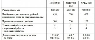
Technical characteristics of cross-planing machines of the industrial group "ASV" are given in table. 1.
Table 1. Cross-planing machines
Safety requirements
When working on broaching machines, it is necessary to strictly observe personal safety measures, which have general principles for all metalworking equipment.
There is a specialized document containing a set of conditions and requirements for broaching machines installed in production. So, for example, safety when cutting on metalworking machines with vertical broaching is ensured by installing a special protective element that protects the operator from injury in cases where the heavy broaching mechanism falls out of the chuck.
During the period of work on horizontal broaching machines, it is mandatory to install a protective folding screen with glass to monitor the process throughout the entire exit area of the broaching element.
It is worth noting that for safety reasons, it is strictly forbidden to install or remove the broach while the metalworking machine is operating. In the case of using a broach whose weight is more than eight kilograms, the use of a special lift is a mandatory requirement.
Specifications
Design features affect all main technical characteristics. The movable work table has T-shaped slots in which workpieces are fixed using clamps.
Dimensions and weight
Machine weight – 900 kg. The dimensions are such that this equipment can easily fit into a room of almost any size:
- length – 115 cm;
- width – 110 cm;
- height – 160 cm.
The vertical table has working surface dimensions of 550x195 mm.
Vertical spindle
The vertical spindle is designed for cutter shanks with Morse taper 4. The adjustable distance between the end and the table is 22–312 mm. Other technical characteristics of the vertical spindle:
- distance from the axis to the end – 100 mm;
- head rotation angle – 45°;
- the greatest movement along the axis is 60 mm.
Vertical spindle rotation speed – 56–2450 rpm.
Vise
Vices also have their own technical characteristics depending on the design features:
- width x height of lips – 150 x 140 mm;
- the largest spread of the sponges is 50 mm;
- maximum rotation angle – 360°;
- scale division is 1 degree.
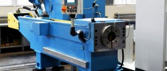
Horizontal broaching machines for internal broaching. Machine 7B510
The domestic machine tool industry produces horizontal broaching machines with the highest traction force of 25-980 kN, with the maximum carriage stroke of 1-2 m. In Fig. 52 shows the 7B510 machine. It is designed for pulling through holes. Using special devices, the machine can also process external surfaces.
Nominal traction force 100 kn; the lowest and highest speeds of the working stroke are 1.5-9 m/min, the reverse stroke is 25 m/min, the supply and removal of the broach is 15 m/min; power of the electric motor of the piston pump is 17 kW. When the machine is equipped with an automatic loading and unloading system, it can operate with an automatic cycle.
Rice. 52. Horizontal broaching machine 7B510
Design
In the hollow part of the welded box-shaped frame 1, the main units of the hydraulic drive, which is the main one for this type of machine, are mounted. On the left is power cylinder 2. The piston rod is connected to the working slide, which, moving in guides along the axis of the machine, serves as additional support. At the end of the rod there is a sleeve with a chuck for securing the left end of the broach 3, and its right end is clamped in the auxiliary chuck 4. The device for installing the part and the part itself rests against the stationary body of the frame 5.
The right part of the frame is attached and is used for mounting units for automatic supply and removal of the broach. The necessary movements are carried out by an auxiliary power cylinder mounted on the right side of the machine. This happens as follows. During the working stroke to the left, the auxiliary chuck 4 slides accompany the broach until they touch the hard stop. In this case, the connection between the broach and the chuck is broken using a spring-loaded cam. After this, a working stroke occurs, carried out by power cylinder 2. During the reverse stroke, the rear shank of the broach again enters the auxiliary chuck and pushes it to the right to its original position.
The machine operates with a full and simple cycle. With a full forward stroke cycle, the broach is supplied, the working stroke is slow, the adjusted working stroke is a slow working stroke when the calibrating teeth and stops are working. During reverse stroke: slow motion and retraction of the broach. A simple cycle differs from a complete cycle by the absence of feed in and out of the broach.
Hydraulic diagram
The basic hydraulic diagram of the machine is shown in Fig. 53. A high-pressure piston pump 30 type NP4M is shown conventionally in the figure. Pipeline 28 is connected to the suction cavity, and pipeline 29 is connected to the discharge cavity. The pump ensures the operation of the machine, carrying out the working and return strokes of the working slide using a hydraulic cylinder 19. The auxiliary hydraulic drive consists of a gear pump 1 built into the piston pump housing, and an auxiliary hydraulic cylinder 12 for supplying and removing the broach.
Rice. 53. Hydraulic diagram of the machine 7B510
Oil from pump 1 is supplied to the support cylinder 31, to the central spool 33 and to the control mechanism, in which there are four pilot spools controlled by solenoids 24, 25, 26 and 27. The central spool 33, together with a disk 35 attached to its end, under by the action of the spring 34 is pressed to the left. The disk 35 has five holes for the passage of screws 37, which regulate the performance of the pump 30 (stator displacement). When pressure is applied under the piston 36, it will rest against the adjusting screw 37 with its rod and limit the advancement of the disk 35 with the central spool 33, which is connected to the piston 32 of the cylinder.
Let's consider the operation of the hydraulic circuit for a full cycle. In the initial position, the working slide is in the extreme right position, the broach is in the retracted position. By pressing the “Start” button on the control panel, the pumps are turned on. In this case, all four electromagnets (24, 25, 26 and 27) are turned off, and the piston pump 30 does not pump oil, since the rotor and stator are concentric.
Broach supply
The broach is supplied by pressing the control button on the remote control. In this case, electromagnet 9 is turned on. Auxiliary spool 7 moves to the left and connects pipelines 3 and 8. Oil from gear pump 1 through pipeline 2, through a bore in the spool body, pipeline 3-8 enters under the right end of the main spool 4 and moves it to the far left position, connecting pipelines 2 and 6. Oil enters the rodless cavity of the auxiliary cylinder and moves the broach. At the end of the broach supply, the limit switch 13 is triggered, which turns off the electromagnet 9 and turns on the electromagnet 27. As a result, the oil goes under the piston 36 and shifts the pump stator to the left to the position adjusted by screw 37 (as shown in the diagram). At the same time, the left end of the broach with its shank enters the automatic cartridge mounted on the right end of the piston rod of working cylinder 19.
Slow working speed
As a result of the above movement, cavity I becomes discharge, cavity II becomes suction. Oil through pipeline 29 enters under the right end of the differential spool 23 and moves it to the left until it stops. Pipeline 29 communicates with pipeline 21, and oil enters the rod cavity of working cylinder 19 and moves it to the left until it stops. The oil displaced from the rodless cavity enters the suction cavity of the piston pump 30 through pipelines 20-28. Excess oil, caused by the difference in the areas of the rod and rodless cavities, is drained through spool 22, which maintains a constant pressure in the cavity of the working cylinder.
Fast working stroke
A fast working stroke is carried out when the cam is pressed on the limit switch 17. This turns on the electromagnet 25. The stator of the pump 32 further shifts to the left, increasing the productivity of the pump and the speed of movement of the working slide. At the end of the working stroke, when the first calibrating teeth of the broach enter the workpiece, the cam presses the limit switch 16, which turns off the electromagnet 25. A slow working stroke begins as a result of a decrease in pump performance, as the eccentricity of the pump block decreases. At the end of the working stroke, the limit switch 15 is activated and turns off the electromagnet 27 - a stop occurs.
Reverse
The reverse stroke occurs when electromagnet 26 is turned on. The piston pump block moves to the left, line 28 becomes discharge, and line 29 becomes suction. Oil through pipeline 28 enters under the left end of the differential spool 23 and moves it to the extreme right position. Pipeline 28 is connected to pipelines 20-21 and both cavities of the working cylinder 19 communicate in this way with the pump discharge line. Due to the unequal areas under pressure, the piston moves to the right. With further movement of the working slide, the cam presses the limit switch 17, which turns on the electromagnet 24. At the same time, slow motion begins due to a decrease in pump performance. At the end of the return stroke, the travel switch 18 is triggered, turning off the electromagnets 26 and 24. The slide stops, the left end of the broach is automatically released and the right end is clamped in the chuck 4 (see Fig. 52), located near the housing 5.
Great Encyclopedia of Oil and Gas
| Multi-cutter attachment for a planer. |
Vertical-broaching machines, compared to horizontal-broaching machines, occupy a smaller area, are more convenient in securing broaches, but have a high workplace due to the need to place the broach under the working position. Vertical machines are used in mass production for processing light and medium-weight parts. The machines are produced for external and internal broaching. Their nominal traction force is 50 - 200 kN, working speed is 0 5 - 14 m / min, carriage stroke length is 600 - 1600 mm.
Vertical broaching machines occupy a significantly smaller area than horizontal ones. It is more convenient to install workpieces for processing on these machines; removal of the part can occur automatically; After broaching, there is no need to return the broach to its original position, since it is automatically secured either to the upper end or to the lower end.
| Horizontal broaching machine model 7510M. |
Vertical broaching machines are used mainly for external broaching.
| General view of a horizontal broaching mill. |
Vertical broaching machines are used mainly for external broaching. The operating principle of such machines is similar to horizontal broaching machines. To increase labor productivity in mass production, continuous broaching machines are widely used.
Vertical broaching machines for external broaching allow the following traction forces: mod.
Vertical broaching machines for internal broaching must be equipped with a guard that protects workers from injury if the broach falls out of the return mechanism chuck. The design of the fence must prevent hands from entering the area between the broach and the fence.
Vertical broaching machines for internal broaching must have a guard to protect workers from injury if the broach falls out of the return mechanism chuck.
According to the hydraulic drive scheme, vertical broaching machines differ little from horizontal broaching machines and have similar control units. All hydraulic drive calculations for reciprocating motion given in the planing machines section are generally applicable to broaching machines.
Machines used for broaching are divided into horizontal, vertical and continuous. Vertical broaching machines occupy a significantly smaller area than horizontal ones. It is more convenient to install workpieces for processing on these machines; removal of the workpiece can occur automatically; After broaching, there is no need to return the broach to its original position, since it is automatically secured either to the upper end or to the lower end. Vertical broaching machines are produced in one- and two-position versions; they can broach one or two workpieces at the same time.
When performing a broaching operation, the cutting speed is regulated by the kinematics of the broaching machines and the drive power of the broaching machines. Small vertical broaching machines have a tractive force of up to 100 kN and can reach cutting speeds of up to 25 m/min. In practice, the maximum service life of broaches is usually achieved at a cutting speed v 5 m/min. However, in order to increase productivity, the cutting speed can be increased to 10 m/min.
When performing a broaching operation, the cutting speed is regulated by the kinematic capabilities and drive power of broaching machines. Small vertical broaching machines have a tractive force of up to 100 kN and can reach cutting speeds of up to 25 m/min. In practice, the maximum service life of broaches is usually achieved at a cutting speed v 5 m/min. However, in order to increase productivity, the cutting speed can be increased to 10 m/min.
Pages: 1 2
Vertical milling head
Designed for cutter shanks with Morse taper No. 4. Dimensions of the seat: depth (including the cylindrical part) - 107 mm, outer diameter - 55 mm, diameter of the seat for the shank - 31.267 mm. Longitudinal rigidity is provided by a corresponding seat at the top, as well as support from two rolling bearings at the bottom. The characteristics of the head are as follows:
- Adjustable distance between the end and the table, mm – 22…312.
- The shortest distance from the axis to the end, mm – 100.
- Head rotation angle, degrees – 45.
- Maximum movement along the axis, mm – 60.
The vertical size of the head cannot be more than 370 mm.
Automation levels
Types of lathes, as well as devices for any other purpose that are used in mass and large-scale production, are called aggregate. They received this name due to the fact that they are assembled from the same type of units (units): beds, working heads, tables, spindle units and other mechanisms. Completely different principles are used when creating machines that are necessary for small-scale and single-piece production. The design of such devices, which are highly versatile, can be completely unique.
CNC lathe
Classification of lathes (as well as equipment of any other categories) according to the level of automation implies their division into the following types:
- manual models, all operations on which are carried out manually;
- semi-automatic, in which part of the technological operations (installation of the workpiece, starting the device, removing the finished part) is performed manually (all other auxiliary operations are carried out in automatic mode);
- automatic, for which you only need to set processing parameters; they perform all other operations independently, in accordance with a given program;
- metal-cutting units with CNC (all processes on such machines are controlled by a special program that contains a coded system of numerical values);
- metal-cutting equipment belonging to the category of flexible automated modules.
The most prominent representatives of metal-cutting machines are CNC devices, the operation of which is controlled by a special computer program. Such a program, which is entered into the machine’s memory by its operator, determines almost all parameters of the unit’s operation: spindle speed, processing speed, etc.
Even the most compact desktop machines can be equipped with a CNC system
All types of metalworking machines equipped with a CNC system contain the following standard elements in their design.
- The operator's console (or console), through which a computer program that controls its operation is stored in the machine's memory. In addition, using such a remote control, you can manually control all parameters of the unit’s operation.
- The controller is an important element of the CNC system, with the help of which not only control commands are generated, transmitted to the working elements of the equipment, and the correctness of their execution is monitored, but also all the necessary calculations are made. Depending on the degree of complexity of the unit model, either a powerful compressor or a conventional microprocessor can be used as a controller to equip it.
- A screen or display that acts as a control and control panel for the operator. This element allows you to monitor the operation of a metal-cutting machine in real time, control the processing process, and, if necessary, quickly change parameters and settings.
The operating principle of metalworking machines equipped with a CNC system is simple. A program is first written that takes into account all the requirements for processing a specific workpiece, then the operator enters it into the machine controller using a special programmer. The commands embedded in such a program are sent to the working elements of the equipment, and after they are executed, the machine automatically turns off.
The use of metal-cutting machines equipped with numerical control allows processing with high accuracy and productivity, which is the reason for their active use to equip industrial enterprises that produce products in large series. Due to their high level of automation, such units are perfectly integrated into large automated lines.
The device of a screw-cutting lathe
Features of operation
Operating personnel are required to place the workpiece in the working niche of the equipment. Next, after launch, the actual processing process begins. A key feature of the functioning of such machines is the fact that the working elements in the form of broaches do not remove chips immediately after cutting, but push them out only after the final exit from the body of the workpiece. Therefore, the range of operator tasks is also expanded due to the need to monitor how correctly machining is performed. On vertical-type broaching machines, the risks of deviations and incorrect cut lines are not so high, since bending of a long workpiece due to its own weight is eliminated.
General classification
Metal processing equipment is divided into 11 groups:
- Metal lathes. External and internal surfaces of rotation are processed. They have one thing in common: rotation of the part around its axis.
- Drilling machines. This group also includes boring machines. Used for passing through and blind holes. They are united by the rotation of the working tool and its simultaneous feeding. In horizontal boring mechanisms, feeding occurs due to the movement of the work table with the fixed part.
- Grinding machines. All such machines use an abrasive grinding wheel as a working tool.
- Polishing and finishing machines. A common feature is the use of abrasive wheels and polishing pastes.
- Gear processing machines. Designed for cutting gear and wheel teeth. This also includes grinding machines.
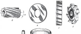
- Milling machines. In this group, the working tool is a multi-edge milling cutter.
- Planing machines. For these machines, the working stroke is a reciprocating movement of the cutter or workpiece.
- Slitting machines. They are used for dividing into parts by cutting a metal profile (angle, channel, rod, etc.).
- Broaching machines. The working tools are special multi-blade broaches.
- Thread processing machines. This includes equipment specifically designed for thread cutting. This group does not include lathes.
- Auxiliary and miscellaneous machines. They belong to a separate group and perform various auxiliary operations.
Classification by type
Equipment of the same type may have different layouts. A milling machine can be called horizontal or vertical - based on the location of the spindle axis. Kinematic schemes for transmitting movements, control systems, and cutting accuracy parameters differ.
Machines of the same type with a similar layout and kinematics, but having different sizes, will be combined into a size range. For example, gear hobbing machines are divided into 12 standard sizes depending on the parts being manufactured (from 80 mm to 12,000 mm). Each standard size of a machine designed for a specific processing of parts is called a model. Each model has its own designations: a combination of numbers and letters indicating the machine group, the maximum dimensions of the workpiece, the difference from the base model.
Design and principle of operation
The mechanical part of planing machines consists of the following elements:
- cast iron or steel frame - the main part of the structure that bears the main loads, used to accommodate the assembly with the cutting tool and the work table;
- working surface - designed for placing workpieces and fastening them;
- guides—necessary for moving the slider or working surface;
- slider - performs translational movements when processing workpieces;
- a cutter used for cutting metal;
- caliper - fixes the cutter at a certain angle;
- gearbox - used to change the rotation speed of the spindle with a fixed workpiece;
- vice for fixing parts during processing.
The design also includes electrical components: motor, controls, monitoring sensors, protection systems. To cool the mechanical elements, a system for supplying lubricants and coolants is used. All machine components are located inside a steel or cast iron body.
The operating principle is based on direct contact of the cutting tool with the workpiece. Machining occurs when the workpiece moves or rotates relative to the cutter.
Processing the part (Photo: Instagram / khuevgen)
Radial drilling machine 2L53
- Radial Drilling Machine Controls
- The device of a radial drilling machine
- Kinematic diagram of a radial drilling machine
- Electrical diagram of a radial drilling machine
- Drill head of radial drilling machine
- Feed activation mechanism
- Technical characteristics of this radial drilling machine
The 2l53 radial drilling machine is designed to perform drilling operations with a maximum drilling diameter of 35 mm. In addition, the machine can perform other operations, such as drilling, countersinking, and reaming.
The machine is equipped with accessories and special tools, which allows you to expand the scope of application and increase labor productivity.
Controls of radial drilling machine 2L53
- Manual table rotation;
- Column barrel clamp;
- Turntable clamp nuts;
- Sleeve clamp on column;
- Electric push-button station;
- Speed dial;
- Gear shift knob;
- Feed shift knob;
- Moving the drilling head along the sleeve;
- Feed switch handle;
- Feed mechanism dial clamp;
- Drill head clamp on sleeve;
- Fine manual spindle feed;
- Rotate the spindle head;
- Feed set handle;
- Drill head clamp
Design of a radial drilling machine 2L53
The radial drilling machine 2l53 consists of the following components:
- Sleeve and plate;
- Barrel;
- Drill head;
- Feed activation mechanism;
- Sled;
- Rotary table;
- Cooling system;
- Threading head;
- Electrical equipment that requires a private electrician to install
Kinematic diagram of the radial drilling machine 2L53
Electrical diagram of the radial drilling machine 2L53
Drilling head of radial drilling machine 2L53
The drill head of a radial drilling machine is made of cast iron, into which the gearbox and feed box are mounted.
The gearbox provides the spindle with eight speeds. Through bevel gear 1, shaft 2 receives torque from horizontal shaft 1. Gears 3, 5 and 7 transmit torque to shaft 3. Shaft 3 will receive different torque depending on which of the pairs of gears 2 and 3, 4 and 5 or 6 and 7 will be engaged. On shaft 3 there is a movable block that enables the inclusion of wheels 8 and 9, 10 and 11 or 11 and 12, which makes it possible to obtain eight speeds on the spindles with a range from 35.5...1400 rpm.
Shaft 5 of the feed box receives rotation through gears 16 and 19. When gears 18 and 24 and 25, 29 and 30 are turned on, torque is transmitted to shaft 7. The shaft receives three different speeds, depending on which of the pairs of gears 25 and 26, 27 and 29 or 28 and 30 will be engaged.
Switching the speeds of the feed box and gearbox is carried out using handles located in the drill head housing.
Feed activation mechanism
The feed switching mechanism is designed for mechanical and manual (accelerated) feed of the spindle and is located in the lower part of the drilling head.
Mechanical feed is carried out by turning handle 2 to the “pull” position, then the toothed fingers 3 engage with part 4 connected to the worm wheel 5.
Manual feed is carried out by handle 1 to the “pull” position.
For a stable drilling depth during manual feed, stop 1 is used.
Technical characteristics of the radial drilling machine 2L53
| Main settings | 2L53 |
| Largest drilling diameter, mm | 35 |
| Spindle offset: | |
| greatest | 1000 |
| least | 290 |
| Maximum distance from the bottom end of the spindle to the plate, mm | 1160 |
| Maximum spindle stroke, mm | 325 |
| Spindle taper | Morse 4 |
| Machine mechanics | |
| Number of spindle speeds | 8 |
| Speed limits, rpm | 35,5. 1400 |
| Number of innings | 6 |
| Feed limits, mm/rev | 0,1. 1,1 |
| Machine dimensions, mm: | |
| length | 2000 |
| width | 790 |
| height | 2390 |
| Machine weight, kg | 2300 |
The machine is equipped with accessories and special tools, which allows you to expand the scope of application and increase labor productivity.
Elements and geometry of the cutting part of the broaches
The round broach (Fig. 21) consists of the following elements. Locking part 1 (shank) serves to secure the broach in the chuck of the machine's traction device; neck 2 – connecting surface. The guide cone 3 and the front guide part 4 serve to center the workpiece at the beginning of cutting. The cutting part 5 consists of cutting teeth, the height or width of which increases by the height of the layer being cut, and serves to cut off the main portion of the allowance. To facilitate the formation of chips on the cutting teeth, chip-breaking grooves are made in a checkerboard pattern.
The calibrating part 6 is designed to give the treated surface the final shape, the required accuracy and roughness. It consists of calibrating teeth, the shape and dimensions of which correspond to the shape and dimensions of the machined surface. The rear guide part 7 is necessary to support the broach as it exits the machined hole. Rough and finishing teeth of broaches have different geometries.
The rough teeth (Fig. 21, a, section A–A) are sharpened. The clearance angle for internal broaches is 3°, for external broaches – 3–8º. The rake angle is selected depending on the properties of the material being processed within 10–20°. The pitch between the teeth is selected from the requirement that at least three teeth operate simultaneously. Lift per tooth – 0.06–0.3 mm/tooth.
A
b c
Rice. 21. Broaches: a, b – round; 1 – locking part; 2 – neck; 3 – guide cone; 4, 7 – front and rear guide parts, respectively; 5 – cutting part (cutting teeth); 6 – calibrating part (calibrating or finishing teeth); f – ribbon; Sz – rise per tooth; t – pitch between teeth; α, γ – main rear and front angles, respectively; c – broach for making an internal keyway
Finishing teeth (Fig. 21, a, section B–B) are made with a strip equal to 0.02–0.3 mm. The rake angle is selected depending on the properties of the material being processed within the range of 0–15°. A zero rake angle is usually assigned for profile broaches, which makes it possible not to lose the geometric accuracy of the teeth during regrinding. The pitch between the teeth t is selected from the requirement that only one tooth participate in the work. Lift per tooth – 0.015–0.03 mm/tooth.