To process parts and workpieces with shaped and flat surfaces, gears, milling machines are used. They are widely used in the industrial and metalworking fields. Despite the variety of types, the main elements of the device are similar. In all machines, the main movement is the movement of the cutter. And the feed movement is made relative to the movement of the workpiece and the cutter.
All capabilities of the milling machine are expanded with these add-ons:
- universal, slotting or vertical head;
- round dividing table;
- universal dividing apparatus;
- device for cutting combs.
Now let's take a closer look at a certain type of milling machines.
Vertical milling machines
This unit is designed for processing workpieces using face, shaped and cylindrical end mills. It is also possible to perform drilling work . Serves for processing gear wheels, frames and corners, vertical and horizontal planes, which are made of steel, cast iron, as well as non-ferrous and various alloys.
In such machines there is no console, and the table moves along the guides of the bed. Thanks to this design, it has extreme rigidity, which, in turn, ensures relatively accurate processing of the part. The spindle head is also a gearbox. The spindle together with the sleeve can be moved in the axial direction.
The vertical milling machine has two types:
- vertical console-milling;
- vertical without console.
Types of cutters, their elements and geometry
A milling cutter is a multi-bladed tool with cutting teeth located around its circumference or at the end, which are the simplest cutters. In Fig. Figure 28 shows the main types of cutters used in mechanical engineering.
Milling cutters are divided into types: cylindrical (Fig. 28, a, b) and end (Fig. 28, f), intended for processing flat surfaces; disk (Fig. 28, c–e), end (Fig. 28, g) and angular - for processing grooves, grooves and splines; shaped – for processing shaped surfaces; modular (Fig. 28, h) - for cutting teeth; worm (Fig. 28, i) - for cutting teeth of cylindrical and worm wheels.
Tooth 4 of a cylindrical cutter (Fig. 28, a) has a cutting edge 2; anterior 1, posterior 3 and occipital 5 surfaces. There is a groove 6 between the cutter teeth. In the cutter section, the following angles are considered: front γ, rear α, sharpening β and cutting δ.
The rake angle γ serves to facilitate the flow of cut chip elements and reduce their shrinkage.
When processing steel γ = 10–20°, cast iron – γ = 10–15°. For hard materials, the angle γ is taken smaller than for soft ones.
The clearance angle α is chosen in such a way as to reduce friction between the back surface of the tooth and the cutting surface. For various cutters, the angle α = 12–25°.
The teeth of cylindrical cutters can be straight or helical at an angle of inclination ω to the cutter axis (see Fig. 28, b). For cylindrical cutters the angle is ω = 30–40°, for disk and face cutters it is ω = 10–25°.
The cutter is made in one piece from tool steels and in prefabricated ones, in which the teeth are made of high-speed steels or equipped with plates made of hard alloys and secured in the cutter body by soldering or mechanically (GOST R 53413–2009).
Rice. 28. Main types of cutters : a – cylindrical spur, where 1, 3, 5 are the front, back and occipital surfaces, respectively; 2 – cutting edge; 4 – tooth; 6 – groove; α – clearance angle; β – sharpening angle; γ – front angle; δ – cutting angle; ω – angle of inclination of the teeth to the cutter axis; b – cylindrical with helical teeth; c – disk groove; g – double-sided disk; d – three-sided disk; e – end; g – end; h – finger modular; and – worm
A cutter with straight teeth cuts into the surface being machined along the entire length of the tooth, which leads to a variable (impetuous) load on the machine and some deterioration in the quality of the machined surface. Cutters with helical teeth work more smoothly, since the cutter teeth cut into the part gradually, while the machine is loaded more evenly.
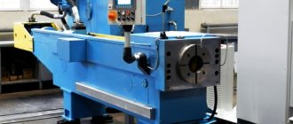
Horizontal milling devices
This type is used for processing parts of small diameters, and it has a horizontal spindle. This design allows the processing of screw, shaped, as well as horizontal and vertical surfaces, corners and grooves. The work is carried out using cylindrical and disk, end, corner, end, and shaped cutters. Processing of a workpiece that requires a screw movement or division is permissible when using additional devices.
The feature that distinguishes it is the ability to move the table perpendicularly and parallel to the spindle axis . All important components are placed on the frame, inside of which there is a gearbox and a spindle assembly. The feed box is located on the console, and the console moves along vertical guides. The trunk with earrings serves to support the tool holder.
Features of the process and cutting modes during milling
Features of the milling process are the intermittent nature of the cutting process with each tooth of the cutter and the variability of the thickness of the cut layer. Each cutter tooth is involved in cutting only for a certain part of the cutter revolution; the rest of the cutter passes through the air, idle, which ensures cooling of the tooth and crushing of chips.
In cylindrical milling of planes, the cutting work is carried out by teeth located on the cylindrical surface of the cutter. When face milling planes, the cutting work is carried out by teeth located on the cylindrical and end surfaces of the cutter. Cutting modes during milling include cutting speed, feed (minute, per revolution and per tooth), depth of cut and milling width B. Cutting speed, mm/min, is calculated as the peripheral rotation speed of the cutter:
V = πDфn/1 000,
where Df is the outer diameter of the cutter, mm; n – machine spindle rotation speed, mm/rev.
Dependencies between feeds: minute Sm, per revolution So and per tooth Sz:
Sм= Son = Sznz = S2x,
where z is the number of tool teeth.
The influence of cutter diameter on machining performance is ambiguous. As the cutter diameter increases, the design cutting speed increases with constant tool life; this is explained by the fact that the average thickness of the cut layer decreases, the cooling conditions for the cutter tooth improve, since the time the tooth spends outside the cutting zone increases.
In order to increase productivity, it is better to choose cutters with a larger diameter, since with an increase in cutting speed, the cutter rotation speed and minute feed increase proportionally (with a proportional increase in the number of cutter teeth). The possibilities of increasing the diameter of cutters are limited by the power and rigidity of the machine, and the size of the tool hole in the machine spindle.
Drilling units
Metalworking machines, which belong to the group of drilling and milling machines, are used for processing horizontal, vertical and inclined surfaces. It is also possible to make grooves in large-sized parts using them.
This type of metal machine has a drilling and milling head, which allows drilling at an angle and processing a surface located at an angle to the horizontal axis. The fact that the working head can operate in reverse mode is its difference, versatility, a certain probability of carrying out two or more popular operations, these machines are very profitable in terms of cost savings and space saving on the production area. No home craftsman would refuse to have such a device at home, because it combines several effective and useful devices.
Universal milling
In small-scale production, this type is used to produce parts by milling. In small mechanical repair shops, as well as in tool shops.
Together with the main components, the spindle assembly and gearbox are located inside the frame. The console moves along vertical guides , and along the cantilever guides move a slide with a rotating mechanism, on which a special table is placed, which moves in a horizontal plane at various angles relative to the spindle axis. With the help of design features, the work performed on such machines is done efficiently and quickly.
Principle of operation
The cutter on such machines is fixed in one position. The accuracy of processing depends on how accurately the workpiece will be placed and moved relative to the cutting edges of the cutter.
For precise and convenient positioning of the fixed workpiece relative to the cutter, there are special mechanisms on the machines. These are located in the console under the desktop:
- work table slide cross feed screw;
- longitudinal feed screw;
- vertical feed screw.
Handwheels are attached to the screws for manual adjustment of positions. Machines of this type are non-automated, completely manual. Therefore, the accuracy of processing largely depends on the qualifications of the milling operator.
The processing accuracy is controlled using a variety of measuring instruments: various rods, calibers, pendulum protractors, plugs, rulers, indicator tools.
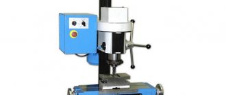
Tabletop machines
Tabletop ones are very compact and thanks to this they are widely popular in equipment repair shops, auto repair shops, and such machines are also installed in schools and vocational schools. With their help the following works are carried out:
- drilling holes, cutting threads, vertical milling with end, face and key cutters;
- horizontal milling with cylindrical, disk and other cutters is also carried out with their help.
The design feature of such machines is their rigidity when installed correctly . If it is installed correctly, then all work will be completed relatively accurately. This type is used in the mass production of various parts. Low energy consumption, their compactness, maneuverability and low cost are the advantages of such machines.
CNC milling machines
These machines have found their application in the mass production of high quality parts. CNC milling machines are much different from ordinary milling machines because they produce equipment using the latest technologies. With their help, you can achieve high quality parts manufacturing at high productivity speed.
In small-scale and mass production, where it is necessary to perform drilling, countersinking, boring holes in parts made of plastic, ferrous and non-ferrous metals, CNC machines are used. This equipment is equipped with a drive that is controlled by a controller connected to any computer.
Among the main advantages note:
- high increase in productivity with a manually operated machine;
- a clear decrease in the need for skilled workers;
- obvious reduction in the transition time to the production of new workpieces;
- more basic and practical equipment;
- high reduction in production cycle time.
CNC Machining Centers
In industrial sectors such as automotive, aerospace, instrumentation, and in areas where mass production of high-quality parts is impossible, CNC machining centers are used. With their help, a wide range of milling, boring and drilling work is carried out. Such machines are equipped with modern drives , which are controlled by special controllers connected to any IBM PC. It is worth noting that the monitoring and control system is equipped with high-quality software produced by global manufacturers. A distinctive feature of this machine is its high cutting speed and high accuracy.
Widely versatile machines
Widely versatile milling machines are used for milling parts made of cast iron, steel and alloys of other materials. They differ from horizontal milling machines by the presence of another spindle head mounted on a retractable trunk. It can rotate at any angle in two mutually perpendicular planes. Both separate and simultaneous operation of both spindles is possible. The overlay milling head is mounted on the rotary head of the machine to add versatility. This makes it possible to process workpieces of complex shapes both by milling and by drilling, countersinking and boring.
Some widely-universal machines do not have a console panel, but instead a carriage moves along the vertical guides of the frame. The carriage has horizontal guides for the slide with a working vertical surface. They are often used to install additional devices, a dividing table, or any dividing device.
The milling group of lathes consists of all the previously listed models. They are distinguished by size and nature of the work performed, but they are all equally used in industry. Each type is used to perform special work that cannot be performed on other types of machines.
Technical data entirely depends on the manufacturer and brand of a particular machine, and the quality of the work performed depends on the professionalism of the master who works on it.
Specifications
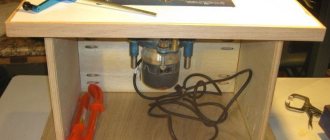
Manual machine
To analyze the technical characteristics of milling equipment, it is recommended to study the passport of a specific model. This document indicates not only the main qualities that a horizontal milling machine has, but also the rules for its operation.
Equipment of this type has a vertical arrangement of components. Therefore, it is necessary to take into account the overall height of the structure. If it is possible to install an additional table, its dimensions are added to the dimensions of the machine. The average weight of equipment ranges from 800 kg to 5 tons.
To analyze the technical capabilities of the model, you need to know the following parameters that a horizontal milling machine should have:
- number of spindle head revolutions. Typically this parameter varies from 400 to 3500 rpm;
- number of speed switching speeds;
- characteristics of the table movement in the longitudinal transverse and vertical direction. The type of feed is taken into account - manual or mechanical;
- power of the power plant;
- presence of a cooling system;
- control type - electronic or manual.
Based on these data, optimal technological schemes for using milling equipment are drawn up. Also, all models have restrictions on the weight of the workpiece and its dimensions. Most often, the manufacturer indicates the maximum permissible weight of the part located in the center of the table.
The additional overhead head can be rotated up to 360°. This must be taken into account when drawing up a processing flow chart.