Universal boring turning tools
Boring turning tools are used for machining holes and internal surfaces. These cutters are divided into two types:
1. For processing blind holes , the cutting plate of such cutters has a triangular shape, and the working part is made with a bend.
Universal turning boring tool for blind holes.
2. For processing through holes , the working part of these cutters also has a bend, and this cutter is used for boring pre-drilled holes or for boring holes in pipes.
Universal turning boring tool for through holes.
The maximum machining depth of the holes of these cutters depends on the size of the holder.
Types of incisors
Boring cutters are divided into several subgroups, depending on the main parameters. Feed on the machine can have several directions. Considering this fact, the incisors can be: left; right.
For each type of hole, the required design of the equipment . The accuracy of processing and operation time depend on this. Depending on its design, the tool is divided into several types:
- Direct. The axis of the holder coincides with the line of the cutting head. Sometimes the parallelism of the axes is maintained.
- Bent back. The axis of the tool head can deviate in a certain direction from the axis of the holder.
- Curved. The holder has a curved axis.
- Retracted. The holder is wider than the tool head.
It must be said that sometimes such forms are not enough. Especially when the part has a complex shape. Especially for such cases, designers are developing unique types of boring tools .
The shape of the holder divides the cutters into several types:
- Round.
- Rectangular.
- Square.
The classification of a tool is also influenced by the manufacturing method. The equipment is divided into groups:
- Solid. The tool is made of a homogeneous material.
- Composite. A carbide plate is used to make the cutting part. It can be fixed to the holder with a regular bolt or soldered.
Modern boring turning tools
Modern boring lathes have quite a variety of designs, and they are primarily used on CNC lathes.
These cutters include various small-sized inserts for processing small diameters.
Small turning inserts.
And standard turning boring bars with replaceable inserts.
Turning boring bars for CNC machines.
When machining with these mandrels, one mandrel is usually used for finishing and another for roughing .
Boring turning tool with replaceable insert for roughing.
Boring turning tool with replaceable insert for finishing.
These cutters are designated: A32T-SVUBR 16 and A25T-SDUCR 11 .
Next, download the 3D models of these cutters and open them in SolidWorks.
Fastening the cutting elements of the cutter
The machine has a special tool holder. Several different cutters can be mounted in it at the same time. The cutter is fixed with special bolts. The tool must be positioned parallel to the centering axis of the machine. The cutting head of the tool must face the spindle.
The turner, installing the cutter, sets its tip . It must coincide with the center axis of the machine (slightly above the center is allowed). If you set the tip below the centerline, the back of the tool will hit the workpiece.
To control accuracy, the cutter is brought directly to the top of any headstock. Adjustment is carried out using pads of different thicknesses . And there should only be two of them. Otherwise, the tool will begin to vibrate.
The protrusion of the cutter from the tool holder should be minimal . If the overhang is too large, the strength of the cutter will become much less. Vibration may occur during boring. The mounting of the cutter must be very reliable. Definitely two bolts.
Where to get 3D models of boring tools for SolidWorks
You can, of course, build them from scratch, but there is no point in this when you can simply go to the website and download the model data.
Search on the Sandvik coromant website
To download cutter models, enter the designation of the holders in the search bar at the top of the site, go to the page for this tool and click on the download page.
Download the 3D model of a turning boring cutter A32T-SVUBR 16 for SolidWorks.
Then open this boring cutter in SolidWorks.
Cutter A32T-SVUBR 16 in SolidWorks
After which we do the same for the A25T-SDUCR 11 and open it in SolidWorks.
Cutter A25T-SDUCR 11 in SolidWorks
A25T-SDUCR 11 boring tool will be used as roughing tool and A32T-SVUBR 16 will be used as finishing tool. This can be seen further in the turning animation.
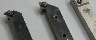
Boring cutter
The boring cutter can be made in several versions. The high-speed type is used for processing various light materials and corresponding alloys, which include aluminum, fluoroplastic, textolite and other materials.
For stronger and heavier compositions, monolithic, carbide boring cutters or with inserts of carbide alloy plates are used. Such products can already work with bronze, raw steel, stainless steel, hardened steel and other materials.
All these varieties, in turn, are divided by the type of holder, which can be square or round. In addition, there is also a division by purpose. According to the functions performed, a boring cutter for blind holes is produced, which is used not only for processing the internal walls of the hole, but also for grooving the bottom, along with its subsequent grinding. There is also a boring cutter, which is used for through holes. It works with cylindrical parts or those with through holes.
Nowadays, such a variety as a boring cutter with replaceable plates is proving to be very popular. They have different profiles and shapes, and most importantly, they come with a set of spare parts that can be used to fasten working plates and holders. Worn plates can be quickly replaced.
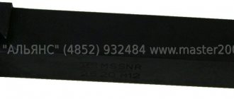
Main Dimensions
Boring tools for lathes, which are designed to work with through and blind holes, are manufactured according to specific size standards.
photo: boring cutter sizes
| Height, mm | Width, mm | Length, mm |
| 16 | 16 | 140 |
| 16 | 16 | 170 |
| 20 | 20 | 140 |
| 20 | 20 | 170 |
| 20 | 20 | 200 |
| 25 | 25 | 200 |
| 25 | 25 | 240 |
| 32 | 25 | 280 |
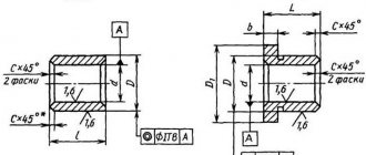
Geometric parameters of boring cutter
The geometry of the working part of the product consists of three main angles, which in their sum always form 90 degrees. This includes:
- The main clearance angle that is formed between the cutting plane and the flank surface of the tool. It reduces friction between the part and the back surface. The larger this angle, the lower the surface roughness that can be processed. Accordingly, the harder the metal, the smaller this angle should be.
- The point angle, which is measured between the front and back surfaces of the tool. It affects the strength of the product, so the larger it is, the more reliable the boring cutter will be.
- The main front, which is measured between the front surface of the tool and the plane that is perpendicular to the cutting surface. With its help, you can influence the size of the deformation of the removed layer.
photo: geometry of boring cutter
Boring tool selection
The boring cutter is selected according to the materials it will work with. First of all, this is the type for blind or external holes. Next, it is very important to look at the material that is being processed. If the basic geometric principle of a given variety is approximately the same, then the materials used will be different.
“Advice of professionals! Under no circumstances should you use high-speed steel products for processing stainless steel, bronze and hardened metal products. This will lead to rapid wear, so it is better to use only products made of carbide materials here.”
You should also not forget about the size, since some cutters simply physically cannot penetrate the hole. For constant active work, it is advisable to have a set of several products or choose a type with replaceable plates. To process blind holes, specialists select products that are half the diameter of the hole being processed.
Cutting modes with boring cutters
The choice of cutting mode largely depends on the cutter bore, hole diameter, type of material and other factors. Depending on the diameter of the hole being processed, when working with through holes, the cutter must be installed below or above their center. At the same time, when working with blind holes, the internal boring cutter is placed clearly in the center so that there are no bosses at the end.
Marking
There are several main brands of cutters, varying in size and composition. For example, T15K6 - the manufacturing material belongs to the titanium-tungsten carbide group with 15% titanium carbide content and 6% cobalt content.
Geometry
All the most important indicators and technical features of the cutter are determined by the value of its angles. In addition to the main ones, there are angles at the apex, as well as angles of inclination of the cutting edge.
Basic cutting tool angles
When sharpening, the most important thing is to ensure accurate angle settings. The edge orientation follows 3 standard planes: rear, front and additional.
Main rear
Increasing the parameters of the main back angle significantly reduces the strength and makes the tool not securely fixed to the cutter holder. Also, an increase in the parameters of a given angle changes the vibration indicators, their frequency and amplitude, and accelerates tool wear.
If the parameters are reduced, this will lead to an increase in the area of interaction between the edge that cuts and the surface of the workpiece being processed.
Main front
This is the main angle that determines the quality indicators of the removal surface. Increasing the parameters leads to an increased number of changes in the upper layer.
If the parameters of the angle are insignificant, then this ensures easier removal of the top layer of metal from the surface being treated.
Cutting angle
The cutting angle should be in the range of 60–100° and located between the front of the cutter and the cutting plane itself.
Point angle
This angle is located between the main surfaces of the back and front. Its parameters indicate the level of sharpening of the apex.
Basic in terms of
The parameters of this angle also characterize the properties of the turning cutter. It is measured between the direction of longitudinal feed and the projection of the main cutting edge onto the plane.
Secondary in plan
The secondary angle in plan is formed from the projection of the auxiliary edge onto the surface with the same direction of longitudinal feed.
Rear auxiliary
This angle is necessary to reduce friction between the flank of the cutter and the workpiece itself. As a result, heat and tool wear are reduced. If the angle is too large, the cutter may weaken and break.
Apex between the back auxiliary surface and the edge of the cutting tool
Measured between the projection of the auxiliary surface and the cutting edge itself. The larger this parameter, the stronger the cutter actually is. Heat dissipation performance is also improved.
Cutting angle
Determines the direction in which the chips flow during the working process. These indicators can be positive, negative or zero.