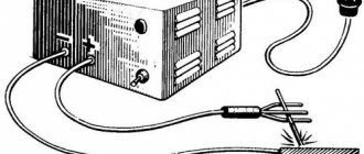
I decided to write my own method on how to assemble a battery charger. I’ll say right away that the charger works exclusively in manual mode and does not damage the battery at all if you monitor the voltage and current.
For assembly we will need: - a 220/16 160W transformer, that is, the secondary winding must have at least 16 volts without load and 10A maximum current. The current can be less (since the battery is charged at 0.1 of the rated current, a 60A/h battery will require a current of 6A) - a dimmer for electric lighting in an apartment or a table lamp. If only the power was right. Personally, I chose this one:
- diode bridge. You can use a diode bridge from the generator of any car, or you can buy 4 diodes designed for the required current on the radio market and assemble them according to the diagram:
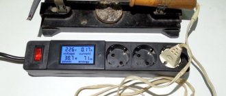
- voltammeter. The easiest way in my opinion. You can order the device on AliExpress here. It looks like this:
Everything in one case - a voltmeter and an ammeter. The device supply voltage is 4.5 - 30V, measures current up to 10A. Or you can install two pointer or digital instruments, a voltmeter and an ammeter, respectively.
- case, capacitor of at least 2200 µF * 25V, switch, 220V fuse, 16V fuse.
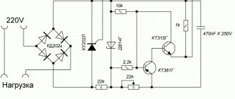
The charger is essentially a powerful power supply that has a 220V input, and the output is regulated from
If the dimmer has a switch, then the SA switch is not needed in the diagram. It is also necessary to install a 16V fuse on the wire or in the housing to protect against output short circuit.
What kind of lighting do you prefer?
Built-in Chandelier
It is also necessary to trust and calibrate the device against an exemplary one (tseshka (multimeter) to help). It is calibrated using two regulators on the back of the board (VR - voltage and IR - current)
Expert opinion
It-Technology, Electrical power and electronics specialist
Ask questions to the “Specialist for modernization of energy generation systems”
THYRISTOR CHARGER 12V To independently make a printed circuit board for a charger for car batteries using a thyristor, you need to have the following materials and tools. Ask, I'm in touch!
Features of regulators for primary transformers
The battery charging current is 10% of its capacity. This means that a battery with a capacity of 60Ah is charged with a current of no more than 6A. The charging voltage when the car is running is 14.5V. Given the required margin, the charger should be capable of delivering 10A at 16V.
A voltage reserve is necessary to regulate and limit the charging current.
In different models of devices it is done in different ways:
- Additional resistances. They turn on after the diode bridge. The simplest design, but with the largest dimensions.
- Transistors. High adjustment accuracy, but the most complex circuit that requires good cooling of power transistors.
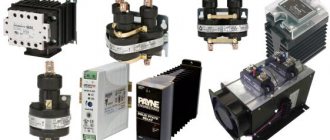
- Thyristor control. Simple diagrams. The adjustment is carried out by a thyristor switch in the primary winding circuit or by thyristors installed instead of diodes in the rectifier bridge.
Types and technical characteristics of thyristor regulator
Due to the fact that the thyristor passes voltage of only one polarity through itself, it cannot be used to control a transformer without additional elements:
- Connect the thyristor to a diode bridge of 4 diodes at the “+” and “-“ terminals. The “~” pins are connected to the open circuit instead of the switch or in series with it. The diode bridge rectifies the voltage and the thyristor is supplied with power of only one polarity.
- Use two thyristors connected back-to-back and for control the control outputs are connected through a variable resistor. Each element opens at its own polarity, and both together control the voltage across the load.
The opening of the thyristor occurs when a current exceeds a certain value and there are two ways to control the opening angle:
- Variable resistance connected between the anode and the control electrode. During the first half of the half-wave, the voltage and control current increase and when it reaches a certain value, depending on the brand of the element. The disadvantage of this circuit is the limited adjustment range of 110-220V, but this is enough to control the charger transformer.
- Control of pulses that are supplied by a separate circuit to the control electrode at a certain moment of the half-wave of a sine wave. The permissible current and voltage of the thyristor regulator depend primarily on the installed thyristors. The most common are thyristors of the KU 202 series, but in some cases the use of other elements is allowed:
- KU 202N – 400V, 30A. Mounted on M6 thread. When adjusting the primary winding, the current of which is less than 1A, they are used without radiators.
- KU 201l - 300V, 30A, fastening - M6 thread. Can be used in the primary winding.
- KU 201a – 25V, 30A, fastening – M6 thread. Can only be used with radiators when adjusted after the transformer.
- KU 101g – 80V, 1A. Looks like a transistor. They are not used in power circuits of chargers, only in control circuits.
- KU 104a – 6B, 3A. Also not used in power circuits.
Area of use of thyristor devices
For what purposes can a device such as a thyristor power regulator be used? Such a device allows you to more effectively regulate the power of heating devices, that is, load the active places. When working with a highly inductive load, thyristors may simply not close, which can lead to such equipment failing to operate normally.
Is it possible to independently regulate the speed of the device’s engine?
It is worth paying attention to the fact that the regulator cannot independently change its speed in asynchronous motors. Thus, the voltage will be fully regulated on the commutator motor, which is equipped with a special alkaline unit.
Expert opinion
It-Technology, Electrical power and electronics specialist
Ask questions to the “Specialist for modernization of energy generation systems”
Thyristor power regulator, thyristor voltage regulator circuits After the user understands the principle of operation of the device and its general structure, he will be able to understand how to assemble or, if necessary, repair a thyristor power regulator himself. Ask, I'm in touch!
Analogs of thyristor KU 202
Foreign analogues of the KU202N thyristor are VTX32S100, H20T15CN, 1N4202. Foreign manufacturers do not produce devices with the same geometric dimensions as the KU202N, so you will need to change the location for mounting the device. It should also be taken into account that their parameters may differ slightly from the thyristor in question, for example, the average current may be 7.5 A.
In addition to foreign devices, you can use the Russian analogue - T112-10. Like KU202N, it has a metal body and an anode outlet for thread. However, its dimensions are smaller, so the installation location will still have to be changed.
How does such a device work?
The characteristics described below will correspond to most circuits.
In this case, there is a certain area that will be under special stress. When the effect of the positive half-wave ends and a new period of movement with a negative half-wave begins, one of these thyristors will begin to close, and at the same time a new thyristor will open.
Instead of the words positive and negative wave, you should use the first and second (half-wave).
The principle of operation of the second circuit will be exactly the same, but it will control only one of the half-waves of alternating current. After the user understands the principle of operation of the device and its general structure, he will be able to understand how to assemble or, if necessary, repair the thyristor power regulator himself.
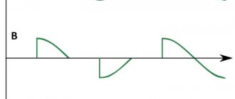
Methods for regulating phase voltage in the network
They change alternating electrical voltage using electrical devices such as thyratron, thyristor and others. When the angle of these structures changes, incomplete half-waves are applied to the load, and as a result, the effective voltage is regulated. Distortion causes current to rise and voltage to drop. The latter changes its shape from sinusoidal to non-sinusoidal.
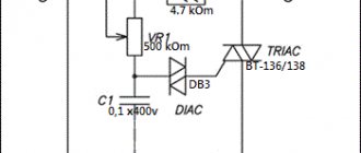
The system will turn on once enough voltage has accumulated across the capacitor. In this case, the opening moment is controlled using a resistor. In the diagram it is designated as R2. The slower a capacitor charges, the more resistance this element has. The electric current is regulated through the control electrode.
This circuit makes it possible to control the total power in the device, since two half-cycles are regulated. This is possible thanks to the installation of a thyristor in the diode bridge, which acts on one of the half-waves.
The voltage regulator, the diagram of which is presented above, has a simplified design. One half-wave is controlled here, while the other passes through VD1 unchanged. It works according to a similar scenario.
When working with a thyristor, a pulse must be applied to the control electrode at a certain moment so that the phase cut reaches the required value. It is necessary to determine the transition of the half-wave to the zero level, otherwise the adjustment will not be effective.
Charger adjustment according to the primary winding of the transformer
When using a rheostat, the energy absorbed by it does not disappear anywhere, but is converted into heat. When there is a large amount of energy, it is advisable to use cooling systems so that the temperature of the device does not become too high. Heat is usually removed by blowing or by immersing the resistor in oil.
Expert opinion
It-Technology, Electrical power and electronics specialist
Ask questions to the “Specialist for modernization of energy generation systems”
Thyristor charger for a car battery: characteristics and circuit Schematic diagram of a triac current regulator for active and inductive loads The design of a triac regulator is similar to a thyristor one. Ask, I'm in touch!
Scheme selection
The proposed circuit, according to which a homemade thyristor charger is assembled, suitable for charging a car battery, has significant advantages. This is simplicity, accessibility, reliability and minimal costs.
If you take the KU202 thyristor as a basis, then you will receive the following additional advantages:
- charging current will be up to 10A;
- pulse type energy is generated;
- assembly requires inexpensive and common parts;
- the circuit can be repeated by those who do not have extensive experience and knowledge in the field of radio engineering.
This is a really simple charger circuit for servicing a car battery. The thyristor circuit allows you to charge batteries with a nominal capacity of up to 100 Ah. After all, the charging current reaches 10A.
- The operating principle of the assembled charger is a phase-pulse type power regulator. With its help you can change the current parameters.
- The transistor circuit is powered by KU202 (control electrode).
- To protect the memory from current surges, a VD2 type diode is used.
- The resistance will affect the charge current, the value of which is 1/1 of the available battery capacity.
- To power the circuit, you need a transformer. It will reduce the mains voltage from standard 220 V to the required 18-22 V.
- If a transformer with a high output voltage is used, then the resistance should be raised to approximately 2 kOhm. It is possible that you will have to individually select the desired resistor.
- The rectifier bridge diodes, like the thyristor, are installed on aluminum radiators. This protects components from overheating.
- If you use conventional elements like D242 or D245, then you will definitely need to mark an insulating washer under the body.
A similar circuit used to assemble a thyristor charger for charging a battery is really simple. Electronic protection is not provided here. A fuse is used instead. It must be installed at the exit.
If you charge batteries with a capacity of up to 60 Ah, then it will be enough to install a fuse with parameters of 6.3 A.
It also wouldn't hurt to connect an ammeter in series. With its help, you can monitor and control the battery recharging process.
The essence of the charging manufacturing process is to make or print a board, and then connect all the components along it. The board with installed elements is enclosed in a housing, all wires are connected and tested.
Other options for thyristor memory circuits
Here are three more options for similar schemes that may be more suitable for someone to repeat. All of them work quite well and are recommended for assembly even by inexperienced radio amateurs due to their simplicity. Plus, you can take a look at the topic of thyristor memory devices here.
Expert opinion
It-Technology, Electrical power and electronics specialist
Ask questions to the “Specialist for modernization of energy generation systems”
Circuits based on thyristors Having understood the principle of operation of the register, it will be easy to understand the circuits and calculate the optimal power for the ideal operation of the equipment where the thyristor is installed. Ask, I'm in touch!