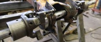
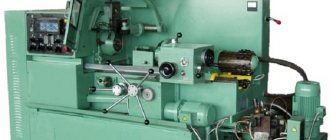
The boring head is the main tool for performing work on machining existing holes to specified parameters. Similar work: whether it is expanding a through hole to the required diameter or shifting it relative to the initially specified axis, is carried out only after the completion of drilling work.
Boring heads can be installed on various types of machines. There are specialized jig boring units, the design of which is optimally suited for boring work. In addition, similar processing can be performed on lathes or milling machines.
Design features of boring heads
The design of the tool allows you to place several cutters at the same time. Practice has shown that the optimal number of cutting elements is 2, provided they are located radially. This configuration has the following advantages:
- Thanks to the balanced arrangement, machining accuracy is improved.
- The vibration level is reduced.
- The dynamic performance of the machine is improved.
Increasing the number of incisors negatively affects the balance of the head. As a result, boring operations will not have high accuracy, especially at high speeds, which reduces the productivity of the machine.
The boring head is mounted on a metalworking unit on a spindle shaft, which transmits rotational torque from the machine drive. To prevent the head from flying out during operation, the tool is secured with screws or nuts.
The main components of the boring head are:
- Hub. As the name suggests, the hub is mounted on the machine spindle using a shank. For reliable fastening there are four screws, two of which secure the quill in parallel.
- Pinol. Mounting location of the working cutter of the boring head.
- Crawler. Movable element of the quill. The movement is carried out by rotating the drive screw. Serves as an adjustment mechanism for aligning the incisors to the centers.
- Shank. Unit for transmitting torque from the spindle part to the cutting elements.
Boring machines
- Home /
- Directory /
- Boring machines
On boring machines, various tools are used for surface treatment: cutters, drills, countersinks, reamers, taps, cutters.
Rice. 1. Tools for boring machines
Boring cutters, based on the cross-sectional shape of the body, are divided into square , rectangular (Fig. 1, a) and round (Fig. 1, b).
Depending on the type of processing, different types of boring cutters are used: through , scoring , grooving and threaded . Lamellar cutters are widely used - the main tool for boring holes with a diameter of more than 20 mm. Lamellar incisors are divided into single- and double-edged (Fig. 1, c). Double-edged plate cutters are made according to the size of the hole being bored.
Boring blocks (Fig. 1, d) are a prefabricated structure consisting of a body 1 and plug-in adjustable cutters 2, secured with screws 3 and 4. The cutters are adjusted according to the diameter of the hole being bored.
Boring heads are used for machining large diameter holes. In Fig. 1, d shows a split boring head for processing holes with a diameter of 130 - 225 mm. The scoring cutters of the head are pre-set in diameter and end to a given size, which makes it possible to process a number of coaxial holes both in diameter and at the ends.
Special reamers with non-adjustable and adjustable knives are used for final machining of holes after preliminary boring them with cutters. An adjustable floating reamer (Fig. 1, e) has two knives 5, mutually moving along a key 7 and fastened with screws 6 while resting on screw 8, the position of which is adjusted depending on the specified size of the hole being machined. The reamer is equipped with hard alloy plates.
Devices for processing workpieces on boring machines
The workpieces are secured on the boring machine table using various universal devices: clamping bars, machine bolts, squares, prisms (see Fig. 2).
Rice. 2. Devices for securing workpieces on machines
When processing holes and planes located at an angle to the base of the workpiece or to each other, squares are used. Workpieces with cylindrical supporting surfaces are mounted on prisms.
Body parts are distinguished by a wide variety of shapes and sizes of machined surfaces and the accuracy of their processing. Depending on this, various designs of boring jigs are used to secure body workpieces and ensure the correct position of the tool relative to the surface being machined.
The cutting tool on boring machines is secured with the help of auxiliary tools: cantilever mandrels, double-support mandrels and chucks. The use of an auxiliary tool is due to the fact that the cutter cannot be directly fixed in the boring spindle or radial slide. Boring bars have rectangular, square or round windows for installing cutters, located at an angle of 45 or 90° to the axis of rotation of the bar. Short cantilever mandrels are designed to secure one or two cutters when boring blind and through holes of short length.
Rice. 3. Mandrels for securing the cutting tool
To bore holes located at a large distance from the end of the machine faceplate, or several coaxial holes, elongated cantilever mandrels (Fig. 3, a). Cantilever mandrels are also used for plate floating reamers (Fig. 3, b). The plate 3 is inserted into the socket of the mandrel and is held with screw 1 from falling out. At the same time, due to the presence of a small gap (0.1 - 0.15 mm) between groove 2 of plate 3 and screw 1, the reamer can self-align (“float”).
A double-bearing boring bar (Fig. 3, c) is a long shaft with a tapered shank at one end for installation in the machine spindle. The other end of the mandrel is fixed in the steady rest of the rear rack of the machine. Along the length of the mandrel there are windows for installing rod and plate cutters.
Processing of workpieces on horizontal boring machines
Horizontal boring machines are among the most common; the designs of other universal and special boring machines are based on them.
Boring machines machine holes, external cylindrical and flat surfaces, ledges, grooves, and less often conical holes and cut internal and external threads with cutters. The most common type of processing on boring machines is boring holes.
Boring of cylindrical holes is performed with cutters mounted on a cantilever or two-support mandrel. The use of a cantilever mandrel is advisable in cases where the length of the hole being processed is l < 5D
, since as the length of the mandrel increases, its rigidity decreases.
Rice. 4. Schemes for processing workpieces on horizontal boring machines.
In Fig. 4, a shows a diagram of boring a small-length hole with a two-edged plate cutter mounted in a cantilever mandrel. The workpiece is given a longitudinal feed. With a short hole length, when it is possible to work with a short rigid mandrel, they are bored with the axial feed of the boring spindle. By boring with longitudinal feed of the workpiece, a more correct hole is obtained due to the constant overhang of the spindle.
Holes with l/D ratio > 5
and coaxial holes are bored with cutters fixed in a two-support mandrel.
In Fig. 4, b shows the simultaneous boring of two coaxial holes. The mandrel with cutters receives the main rotational movement, and the workpiece receives longitudinal feed in the direction from the rear post to the spindle head.
Holes of large diameter, but short length, are bored with a cutter fixed in the radial support of the faceplate (Fig. 4, c). The faceplate with the cutter is given the main rotational movement, and the table with the workpiece is given the longitudinal feed. Holes with a diameter of more than 130 mm are processed with boring blocks and heads.
Boring of parallel and mutually perpendicular holes is performed from one installation of the workpiece. After boring the first hole, move the table in the transverse direction or the spindle head in the vertical direction by an amount equal to the center-to-center distance, then bore the second and other holes. If you need to bore mutually perpendicular holes, then after boring the first hole, turn the table 90° and bore the second hole.
Boring of conical holes is carried out with boring heads mounted in a boring spindle, which is given an axial feed. Conical holes with a diameter of more than 80 mm are bored with a cutter using a universal device mounted on the radial support of the faceplate (Fig. 4, d).
Drilling, countersinking, reaming, counterbore, countersinking and tapping are performed on boring machines in the same way as on vertical drilling machines. The tool is fixed in the boring spindle and the main rotational movement and axial feed are imparted to it. The workpiece placed on the machine table remains motionless.
How the tool works
The shank is inserted into the tapered hole of the spindle mechanism of the jig boring machine.
For precise work without vibration, the tail part of the head must exactly follow the contours of the spindle. After installation, the tail section is fixed with a standard machine screw. According to the requirements of processing technology, the workpiece must be carefully fixed in a stationary position to avoid displacement during boring operations. This position allows the head to accurately perform its functions with minimal risk of defects.
When processing small holes, the diameter of which does not exceed 40 mm, the position of the cutters is adjusted only by moving the slide.
When working with holes of larger diameter, after adjusting the slider, it is returned to its initial position and, after loosening the fasteners, the quill is moved into the hub until it stops. Thus, boring is performed in two stages.
Types of boring heads
The metalworking tool under consideration is divided into two types, which differ in the type of feed:
- Manual.
- Automatic.
Let's take a closer look at them.
Manual feed heads
This type was used on the very first boring machines with the simplest numerical control systems.
They are used for semi-finishing of holes in metal products with a diameter from 10 to 630 mm. In modern conditions, they are actively used as a tool for performing work for which there are no high requirements for accuracy class (up to 0.04 mm). The manufacturing material used is high-quality tool steel, which is subjected to high-temperature hardening and finishing on grinding machines.
Automatic feed heads
Devices with automatic feeding are characterized by versatility of use. They are used to sequentially perform the following types of processing:
- boring;
- trimming;
- turning.
And other work that may be necessary during the processing of metal products. The universal design allows them to be installed not only on milling machines, but also on horizontal boring and jig boring equipment with numerical control.
In the modern metalworking industry, automatic tools play an important role, since the latest machines are oriented towards the use of such equipment.
The design of modern machines, for example those produced by SORALUCE, provides for the installation of several heads on one piece of equipment. The multi-spindle modular system allows for work of various diameters and depths, which increases productivity by eliminating the time required to replace removable cutting elements.
Based on the depth of impact, there are two main groups:
- Shallow. Used in the initial stages of work. This type of design is easy to implement. Modes of use differ in feed speed and maximum depth of impact. Regardless of the mode and type of design, all heads have a set of removable cutting elements, which are secured with special clamps.
- Deep. This type is designed for boring holes in metal at great depths. Compared to a shallow-depth tool, the design is more complex due to the presence of a mechanism for removing metal shavings formed during operation. Processing by-products can be removed either externally or internally. It is possible to install removable cutters.
Boring through holes
Depending on the size of the hole (depth and diameter), for through boring, through cutters, mandrels or boring bars are used, on which boring heads or cutter blocks are installed. Pass-through cutters for boring through holes have a number of differences from turning tools for external turning: their rear corner is sharpened so that the cutting part corresponds to the processing size, and the front part of the holder is narrowed and has an elongated shape. On lathes, the cutter is mounted either in a mandrel with a conical shank on the tailstock, or on a caliper tool holder in the longitudinal direction. Boring machines use cutters that are installed in special mandrels.
For through boring, multi-edge mandrels of various designs are also used, having the form of a thick elongated cylinder on which several cutting plates are located. Such a tool is much more expensive than cutters, but allows you to process much greater depths and with better accuracy.
Boring bars (boring bars) are used for boring with great depth, increased accuracy or several coaxial holes. This type of tool is made in the form of long cylindrical rods of increased precision with a diameter of 30 to 200 mm and a length of one to three meters. Along the entire length of the boring bar, at a certain distance, there are through recesses (windows) for attaching a cutting or measuring tool. One end of the boring bar is attached to a conical mandrel and installed in the spindle, and the other is supported by a steady rest or a special support. Before boring, the axes of the holes and boring bars must be aligned to the specified accuracy.
Cutters for boring heads
All cutters, regardless of type, consist of a holder on which the cutting element is attached.
The holder is mounted on the standard place of the working equipment. The structure of the cutting element, which is called the head, has its own characteristics:
- Solid heads are made from high-quality tool or high-speed steel. This type of design does not provide for division into a holder and a cutting element. Very rare due to high cost.
- The working part is a soldered plate made of a high-strength alloy, which contains various additives that improve the quality of the material. The most common type.
- There are designs in which the cutting plate is attached to the holder mechanically. This method is used for cutting parts made of metal-ceramic materials.
Boring heads differ according to the method of application:
- For blind holes.
- For through holes.
On fixtures for blind holes, the plate has a triangular shape. This is very useful for boring jobs that start from the center of the hole. The longer the holder, the greater the range of action of the tool.
There are also universal boring cutters, which provide for the installation of replaceable inserts of various shapes, which allows you to perform a variety of work with the same holder.
Boring blind holes
When boring blind holes, stop cutters or mandrels with inclined cutting plates are used. In both cases, the problem of processing the bottom (inner end) of the hole arises, since in the middle there remains a small conical zone that is not touched by the cutter. Therefore, such boring is performed in the following sequence:
- drilling (or reaming a hole) to the maximum possible diameter;
- rough boring, after which an allowance of several millimeters remains;
- processing the bottom of the hole with a special end trim to the required cleanliness;
- finishing boring to a given size.
When blind boring, special attention is paid to machining near the bottom of the hole. Therefore, 5 mm before reaching the full depth, the feed should be reduced, and the last section should preferably be done manually. Passing cutters are used only for small boring depths (100÷150 mm). In all other cases, boring heads of various types are used.
Boring head selection rules
First of all, you need to decide on the purpose of the tool.
For rough-type boring work, devices with two blades are used, provided there is a mechanism for adjusting the allowance. Finishing is performed with one cutting element, which allows for high precision work. The most important characteristics of the instrument in question are:
- Working stroke of the slider.
- Maximum number of revolutions.
- Feed speed.
For beginner lathe operators, we recommend using Sandvik Coromant products. Their heads are easy to use, allowing you to quickly learn the necessary skills.
Boring heads are not the most popular tool, although the role of these devices in the field of metalworking is difficult to overestimate. Have you encountered boring work? Were the operations performed on CNC machines or not? Describe your impressions in the comments.
