Even with proper and careful operation of the angle grinder, it may break down under the influence of various factors: wear of components, excessive heating of live parts, unstable voltage in the network. Very often, grinders have defects in the armature and electric stator in the engine.
In order to accurately establish the reasons why they may fail, you need to know how to check the armature of an angle grinder with a multimeter. This will be required if the grinder unexpectedly does not turn on during operation, before taking it in for repairs or purchasing components.
Briefly about the design of the grinder
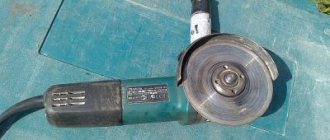
Grinder or angle grinder (angle grinder) - used in construction operations when it is necessary to process hard building materials: stone, metal, wood and others.
The main part of the angle grinder is a built-in electric motor, which can operate both from a household 220 V AC source and from a battery. An electric motor consists of 2 elements: an electrostat and a rotor. The latter rotates when the engine is running, therefore it is also called an armature. In order to fix an angle grinder, you will need to check the stator and rotor separately.
If you don't have an ohmmeter?
If you don’t have a multimeter, you will need a 12 Volt power source and a light bulb for the appropriate voltage. Any car enthusiast will have no problems with such a set. The positive and negative terminals are connected to the plug of the electrical appliance. An incandescent lamp is placed in the gap. The result is observed visually.
The armature shaft is rotated by hand, the lamp burns without jumps in brightness. If attenuation is observed, the engine is faulty. Most likely, an interturn short circuit has occurred. Complete disappearance of the glow indicates a break in the circuit. The reasons may be non-contact of the brushes, a break in the winding, or a lack of resistance in one of the lamellas.
Preparing the tool for testing
If, when you press the start button, the grinder does not turn on and the electric motor does not rotate, then check the rotor and electric stator.
To do this, you need to prepare a workplace, disassemble the angle grinder, clean it of dirt and perform a visual inspection. After this you can start calling.
Visual inspection
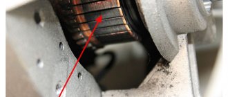
Quite often, the grinder still starts, but its characteristics no longer meet the norm. In almost half of the cases this is due to a burnt out rotor. This can be detected visually without opening the case when:
- During operation, sparking was detected on the commutator.
- During startup of the angle grinder, there may be a voltage drop in the house electrical network.
- Engine operation is accompanied by jerking.
- The smell of burnt winding wires is emitted from the motor housing.
- The tool does not develop speed and operates with low power.
Important! Similar signs appear when the brushes wear out. After replacing them, these malfunctions in the operation of the unit stop. If this is not the case, then the anchor is still to blame for the failure.
When the armature is not operational, the engine overheats. The insulating coating of the wires begins to melt, which ultimately leads to a short circuit between them. Then the process of soldering the electrical contacts that connect the rotor windings and plates begins. The current is not supplied to the electric motor, and the angle grinder becomes inoperable. The stator of an angle grinder similarly often becomes the reason for its failure.
Disassembling an angle grinder
In order to test the armature or stator with a multimeter, the grinder will need to be disassembled. Before starting work, you need to study the factory assembly diagram of the angle grinder. It is important not to spoil the design of the angle grinder due to incorrect actions, and you also need to choose the correct screwdriver configuration to unscrew the screws, otherwise they will have to be drilled out.
In different modifications of the angle grinder, the fasteners are used in different lengths, so you need to fix the locations of the screws. It's better to take a photo of the disassembly on your smartphone.
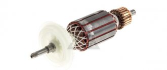
The armature is made of a winding and a magnetic circuit. There is a drive gear at one end and a commutator at the other. The magnetic core is made of soft plates with grooves, protected by a special insulating layer.
There are 2 rotor windings in the grooves, each representing half a turn, the edges of which are combined in pairs in lamellas. In the 1st groove there is: the beginning of the 1st and the end of the last, closing on one lamella.
Typical faults
The electric motor armature is not subject to wear under normal operating conditions. Only the brushes are replaced, measuring the permissible length. But under prolonged loads, the stator windings begin to heat up, which leads to the formation of carbon deposits.
Due to mechanical stress, the armature of the electric motor may become distorted if the bearing units are damaged. The engine will work, but gradual wear of the lamellas or plates will lead to its final failure. But to save expensive equipment, it is often enough to carry out preventive repairs and the device can be used for a long time.
Negative factors affecting the armature of an electric motor include moisture getting on metal surfaces. Prolonged exposure to moisture and the appearance of rust are critical. Due to red accumulations and dirt, friction increases, which increases the current load. The contact parts get hot and the solder can flake off, creating an intermittent spark.
The service center can help, but this will require certain costs. You can deal with the breakdown yourself by reading the question: how to check the armature of an electric motor at home. For diagnostics you will need a device that measures resistance and tools.
Recommendations and safety precautions
Digital multimeters, especially those intended for household use, have a certain error. Therefore, pointer modifications of meters provide a higher level of testing.
In the case where you don’t have a dial multimeter at hand, you will need to take into account the existing error of the digital multimeter. In the version of measuring resistance with a reading of 200 Ohms, the probes are combined. When o - there is no error, if a different number - it will demonstrate the magnitude of the error.
Assuming the scale is 0.15 ohms, therefore, when testing, the reading of 0.15 ohms is zero.
When monitoring electric motor components, the user must follow the following safety recommendations:
- Before starting testing and disassembling, disconnect the equipment from the electrical network by disconnecting the power cord from the outlet;
- the workplace must be clean, there should be no unnecessary tools or components on it;
- testing is carried out in good lighting;
- work is carried out with protective gloves, since sharp pieces of plates and wires may stick out in disassembled units, which can injure your hands.
Working with an ohmmeter
Sincere could occur due to the loss of electrical contact in one of the lamellas. To measure resistance, it is recommended to place probes on the side of the current collectors. While rotating the motor shaft, observe the dial readings. The screen should show zero values. If the numbers slip by even a few ohms, then this indicates carbon deposits. When an infinite value appears, an open circuit is judged.
Regardless of the results, you should next check the resistance between each adjacent lamellas. It should be the same for each measurement. In case of deviations, you need to inspect all the connections of the coils and the contact surface of the brushes. The brushes themselves should wear evenly. If chipped or cracked, they must be replaced.
The coils are connected to the core by wiring that may have come loose. Solder often does not withstand shock from drops. In a starter, the current through the contacts can reach 50A, which leads to burnout of poor-quality connections. External inspection determines the location of damage. If no malfunction is found, then measure the resistance between the lamella and the coil itself.
How to check the anchor of an angle grinder with a multimeter
A multimeter, which is used at home by almost any craftsman, can help him check the serviceability of the electrical components of the angle grinder. They can diagnose the presence of an interturn short circuit in the electrical windings of an electric motor and measure the resistance between the lamellas.
Before checking the rotor of an angle grinder, the user must know the main malfunctions that occur in its electric motors, prepare the power tool for testing and disassemble it correctly.
Main rotor malfunctions:
- Breakage of current conductors;
- Short circuit between electric turns;
- breakdown of the insulating coating, the winding closes to the steel base of the armature;
- Wiring the terminals of a heavily worn collector.
Preparing the anchor for testing
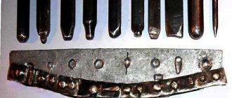
Before ringing the anchor, it is removed from the housing and prepared for diagnostics. The collector lamellas will need to be thoroughly cleaned of graphite contamination, otherwise the test will be ineffective.
Remove dirt with a rag soaked in alcohol. When there is an additional full layer of soot on the lamellas, it is removed with fine sandpaper.
They also make sure that there are no noticeable abrasive streaks left on the electric commutator, which lead to worse contact between the lamellas and the brushes and accelerate their wear. If the excavation is very deep, the rotor is replaced.
Important! During the inspection, pay attention to the armature winding; there should be no breaks or external traces of combustion on it, and the electrical contacts where the winding touches the lamellas are checked for integrity.
Anchor continuity
In order to check the armature of an angle grinder with a multimeter, you will need to complete 2 steps. First, you need to ring it for the existence of a breakdown. To do this, the measuring device is set to the electrical circuit continuity mode with sound indication. Then the first probe is passed along the lamellas, and the other along the anchor body.
The next stage of examining the rotor with a multimeter allows you to measure the resistance between the nearby windings. The meter is set to ohmmeter mode at the lowest threshold, usually 200 Ohms. After this, the probes are brought to the adjacent collector lamellas and the readings are recorded on the display. In this case, it is very important that R of the tested lamellas is equal, otherwise the armature is considered faulty.
Important! In the case where R = 0 on a specific winding, the armature has an interturn short circuit. This failure can be more accurately determined using a specialized device.
Repair, replacement, rewind
After diagnosing and determining the types of rotor faults, a decision on repair methods follows . It is possible to do the repair yourself, which will involve rewinding the armature yourself. If this option seems labor-intensive and complicated, you can follow a simplified scheme and replace the burnt out rotor with a new one that matches the model of the angle grinder. The simplest, but also expensive option is to contact a special service department .
When making a decision about repairing an anchor with your own hands, the information available in the articles “How to remove an anchor from an angle grinder”, “Replacing and repairing an angle grinder’s anchor”, “Rewinding an angle grinder’s anchor with your own hands” will help.
Checking the stator with a multimeter
The electrostator is located on the outer portion of the electric motor, on top of the rotor. Before checking the stator, you need to dismantle it and remove the brushes, and then remove the gearbox. First, carefully inspect the winding and make sure that there are no visible breaks or other defects on its surface.
Possible causes and signs of a non-working angle grinder stator:
- A sharp increase in voltage;
- penetration of moisture into the engine;
- overload of power tools and created internal overheating of components;
- abruptly removing the cord from the outlet while the tool is running;
- the appearance of a smell of burnt rubber or plastic;
- case overheating;
- the appearance of smoke from the electric motor during its operation;
- slow rotation of the shaft or its complete absence;
- The grinder sharply picks up speed.
Important! When the protective coating on the winding wires overheats, the varnish melts, releasing a pungent odor, and the winding insulation is damaged. Short circuit of even one winding completely removes the tool from working condition.
The multimeter allows you to check for a break in the stator windings; to do this, you must perform the following steps:
- The meter is set to R mode to a maximum of 200 Ohms.
- They begin checking the error of the multimeter, to do this they touch the probes together, the tester arrows should point to “0”.
- Touch the probes to the terminals on the windings, if the instrument scale shows “infinity”, the winding is not working and rewinding is necessary.
- Check for the presence of a short circuit on the housing. A very dangerous condition of a power tool that not only causes a loss of power, but is also a potential source of electric shock to the user.
- Includes resistance measurement.
- The red probe is installed on the winding terminal, the black one is fixed on the stator housing.
- When the stator winding short-circuits to the housing, R on the display is less than on the working winding. This failure can only be eliminated by rewinding the windings.
- To measure an interturn short circuit in an electrostator, R is measured on a separate winding.
- Determine the “0” point of the windings by measuring R of each. The least resistance will indicate a faulty one.
A multimeter allows you to quite accurately determine malfunctions in the armature and stator of an angle grinder motor. A detected malfunction can be eliminated by rewinding the electric motor or replacing it from the repair kit. Currently, there are enough such sets in the retail chain for most popular models of angle grinders.
Important! When replacing faulty engine components, it is imperative to replace new brushes, especially since they are completely inexpensive.
After repairing the stator or rotor, the tool is reassembled using the saved disassembly photographs. Check the functionality of the tool. If everything is done correctly, the grinder will serve its owner for many more years.
Diagnostics of internal parts
The armature winding of the electric motor should not have carbon deposits or dark spots similar to the consequences of overheating. The surface of the contact parts and the gap area should not be dirty. Small particles reduce motor power and increase current. Do not disassemble devices with a plug connected to the network for safety reasons.
It is recommended to film the disassembly process to eliminate complications during the reverse process. Or you can write down each step of your actions on a piece of paper. Some wear of brushes and lamellas is allowed. But if scratches are found, you should find out the cause of their origin. Perhaps this was caused by a crack in the case, which can only be noticed under load.
Register of collectors: who controls it
Forced collection of debts is possible only by employees of the FSSP, or in case of bankruptcy (when the debtor’s property is sold). Collectors have the right only to convince, ask, talk. Forceful methods, such as arrest or seizure of property, as well as aggressive influence on the debtor are prohibited.
The work of collectors is regulated by Federal Law No. 230 “On the Protection of the Interests of Citizens...” For simplicity, this law is called the law “On Collectors”.
The work of collectors in the legal field is controlled by bailiffs - they have the right to consider complaints from debtors and check the legality of the actions of collectors. The register of collectors, which includes organizations that have been audited and confirmed compliance with Federal Law No. 230, is posted on the FSSP website.
Pressing anchors under guy ropes in workover teams
1. The design, in its technical design, must meet safety requirements and technical conditions.
2. Receiving bridges should only be transported and installed at the wellhead using a T-150 or K-701 tractor with a working hydraulic suspension.
3. Receiving walkways at the wellhead are installed horizontally or with a slope of no more than 1:25 away from the wellhead.
4. Walkways must be equipped on both sides with gangways in accordance with the requirements of safety rules.
5. Receiving walkway racks must provide the ability to lay pipes with a stack height of no more than 1.25 m, and have metal anti-roll bars that protect the pipes from rolling out.
6. The running track must be made of at least 1 meter wide from 50mm thick boards, and the gangways must be at least 1 meter wide and 40mm thick boards.
Installation of the lifting unit
Before installation of the lifting unit, the well must be plugged.
Before starting work, the machine operator must check:
— the state of the workplace;
— presence of fences and devices, reliability of fastening of protective covers;
— serviceability of tools and equipment, instrumentation;
— availability of diesel fuel and lubricant;
— reliability of fastening of the traveling rope;
— correct fastening of guys to anchors;
— brake system: the brake handle, with the brake fully applied, should be at a height of 800-900 mm from the floor of the unit frame.
- the end of the fixed branch of the traveling rope, as well as all guy lines of the mast, must be secured using at least four clamps.
When installing the unit to the well, its position must be provided in such a way that it can be conveniently controlled, as well as monitor the operator working at the wellhead and the movement of the traveling block.
Lifting units (with the exception of the AKM-28 unit) must be reinforced with guys made of steel ropes so that they do not cross roads, live power lines, and transition areas.
The tower (mast) must be centered relative to the axis of the well.
Before starting work, the unit must be grounded by connecting a ground wire to the casing string.
Installation of the lifting unit.
The unit is moved to the wellhead in reverse. After installing the unit relative to the mouth, the following operations must be performed:
— engage the parking brake and place chocks under the wheels;
— put the gearbox and transfer case control levers in the neutral position;
— unload the car’s springs with screw jacks;
— attach power and wind guys to the crown block, mast and remove the bolts securing the mast to the middle support;
— engage quarter gear of the vehicle’s gearbox and first power take-off speed;
— when the pressure in the pneumatic system of the unit reaches 0.6-0.8 MPa (6-8 kgf/cm2), switch the vehicle’s gearbox to first gear to raise the mast;
— any gearbox and gear shifting must be done with the vehicle’s engine clutch disengaged.
Work at height on the installation, dismantling and repair of towers and masts at night, with wind speeds of 8 m/s or higher, during thunderstorms, heavy snowfall, sleet, rain, fog with visibility less than 100 m must be suspended.
Power and wind guys A-50 must be secured from the anchor at a distance of 28 meters and at an angle of 450. Inaccuracy in the installation of anchors is allowed plus or minus 1.5 m.
Before lifting the mast, it is necessary to pressurize the hydraulic jacks and supply fittings. When the pressure reaches 120 kg/cm2
wait for 2-3 minutes. There should be no oil leaks anywhere.
When the pressure reaches approximately 5 MPa (50 kg/cm2
) the mast must rise. If the mast does not rise, move the hydraulic distributor handle to the neutral position and troubleshoot, check the correct connection of the supply fittings. The mast lifting speed is controlled by a needle valve.
Before lowering the mast, fill the hydraulic jacks from below with oil and create a pressure of 1.5-2.0 MPa (15-20 kg/cm2
).
To lower the mast into the transport position, set the hydraulic distributor handle to the left position. When lowering the mast, supply oil to the upper cavities of the jacks only until the mast passes through the vertical position, after which set the hydraulic distributor handle to the neutral position. The mast then lowers under its own weight.
Before extending the upper section of the mast, connect the limiter cable of this section to the limit switch handle. Check the correct position of the extension rope on the rollers and in the traveling block shackle. After this, placing the drum clutch valve handle in the “Quiet” position, lift the upper section at the lowest speed (first gears of the gearbox and power take-off).
After the support shoes of the upper section rise above the gates of the lower section by 100-150 mm, set the crane handle to the “Off” position, simultaneously braking the drum. Then, through the lever system, install the valves into the working position and carefully place the upper section on them, gradually releasing the drum.
Attach the wind guys to the anchors, and the power guys to the front buffer of the car. By rotating the adjacent nuts, tighten the power guys with a force of 400-500 kgf, which corresponds to tightening the coupling nut with a lever 800 mm long, with a force of 25 kgf. Wind guy lines are tensioned with such force that there is no noticeable sagging of the ropes. When operating the unit with a hook load of more than 30t, it is recommended to increase the tension in the two front wind guys and monitor the condition of the anchors. During work, periodically tighten the power bars.
Before lowering the upper section of the mast, insert the upper section extension rope into the traveling block shackle. By lifting the traveling block at the lowest speed, lift the upper section 100-150mm above the gates. Retract the bolts into the lock bodies, then lower the upper section of the mast down, while constantly slowing down the drum.
To avoid breaking the upper section, before extending and lowering, all screw guys must be spread out to the maximum possible extent.
Installation of air defense.
Dismantle the Xmas tree and check the condition of the O-rings and grooves of the flange connections.
When working according to scheme 1, a sealing head is mounted on the crosspiece (or through an adapter coil). The sealing coupling is part of the shut-off assembly and must be located on the work site.
When choosing scheme No. 2, the preventer with pipe rams is mounted on the crosspiece (or through an adapter coil). The dies must correspond to the diameter of the remote pipe of the shut-off arrangement.
When choosing an air defense piping scheme with two preventers, a preventer with blind rams is first installed, and a preventer with pipe rams is installed on it. In this case, the preventer with pipe rams is equipped with remote control by means of rods with a length of at least 10 m, made of pipes with a diameter of 73 mm. In front of the steering wheels there should be information about the direction of rotation and the number of revolutions for closing - opening the preventer and marks indicating the complete opening and closing of the preventer rams.
It is allowed, in agreement with the blowout service, to carry out perforation and blasting work in the column with subsequent dismantling, installing an upper preventer with blind rams and continuing work with one preventer (except for wells of the 1st category). In this case, repeated pressure testing of the preventer remaining in the piping is not required.
The profile of the flange O-rings must match the profile of the grooves on the flanges of the Christmas tree and blowout preventer equipment. The rings and grooves must be cleaned, free of ice and dirt, and fit tightly into each other when installing the air defense.
The air defense system is connected to the crosspiece of the fountain fittings using all studs, and the nuts must be screwed in such a way that after screwing the nut on the stud, 2-3 turns of thread remain. They are tightened crosswise.
After installing the blowout prevention equipment, the well is pressurized with process water to the maximum expected pressure, but not higher than the pressure test of the production casing.
After installing blowout prevention equipment on a well with a perforated or leaking column, the BOP is pressurized to a pressure of at least 3.0 MPa. The testing pressure is determined based on the technical condition and injectivity of the well and is indicated in the work plan.
The results of crimping are documented in a report.
Exploitation
Free access to the wellhead for BOP maintenance must be provided.
Before starting a shift, it is necessary to check the tightness of flange connections and monitor the technical condition of moving elements (check for ease of opening and closing). The test results must be recorded in the equipment inspection log. At least once a decade, a control check of the blowout prevention equipment is carried out by the team foreman. The test results are recorded in the equipment test log.
If it is necessary to replace rams, you should follow the manufacturer’s recommendations reflected in the data sheet for the preventer. The work is carried out under the guidance of a specialist – a blowout prevention equipment mechanic.
After replacing rams or preventer units directly at the wellhead, it is necessary to pressurize the preventer installation to the pressure of the string.
Frequency of inspection of ram preventers:
— hydraulic pressure testing — every 6 months
— flaw detection — once a year.
Prohibited:
Perform blows on the air defense body in order to clean the surface of dirt and ice.
Carry out welding and repair work on connecting seams on the body;
Heat the preventer elements with open fire.
Walk or rotate the string of tubing or drill pipes; the load on the rams is not allowed to exceed 20 tons.
Pipe preparation
Preparation of tubing and drill pipes (DP) is carried out in accordance with RD 39-2-132-78 and “Instructions for the operation, repair and accounting of drill pipes” (VNIITneft, Kuibyshev, 1979), RD 39R-05753520 -001-95 “Regulations on acceptance, storage, rejection, movement accounting and the procedure for transferring tubing and downhole pumping rods to other areas of destination at OJSC Tomskneft of the East Oil Company.
At the pipe base (PRCTiT), hydraulic tests, templates, marking and sorting of pipes, as well as calibration of threads are carried out. Directly at the well pad, an external inspection, re-templating, laying of pipes in the order of lowering into the well and measuring their length are carried out.
S Transportation of pipes to the well must be carried out using special transport. When loading, wooden spacers must be laid between rows of pipes to protect the pipes from impacts. In this case, the ends of the pipes should not hang down or protrude beyond the dimensions of the vehicle by more than 1 meter. Transportation of pipes without safety rings and nipples is prohibited.
S When unloading and laying pipes at the well, it is necessary that the coupling ends are facing the wellhead. In this case, dropping pipes, hitting each other, or dragging them is not allowed.
S When working with pipes, it is necessary to have a reserve of 50 m of additional reserve for every 1000 m.
S During a visual inspection of pipes at the well, the condition of the outer surface of the pipe, coupling and their threaded parts is determined. Small nicks found on the surface of the pipe can be removed using a file.
S Tempering of pipes must be done when lifting pipes from the walkway for lowering into the well.
If the template does not pass through the pipe, it is rejected. On pipes rejected during inspection, it is necessary to mark “REJECT” with paint that is resistant to climatic conditions. Rejected pipes should be stored separately from the main pipes.
S The prepared pipes must be stacked on racks in the order of descent into the well, and wooden spacers must be placed between the rows. The ends of the couplings of each row of pipes should be on one common straight line, and subsequent overlying rows should step back from each laid row by the length of the coupling.
S When using pipes of different diameters and designs, it is necessary to group them by type and size. It is recommended to screw the sub for screwing them together in advance into the coupling of the last pipe of the descending section.
S The length of the pipe must be measured from the free end of the coupling to the end of the threaded part of the pipe using a proven steel tape measure. It is recommended to apply the serial number and measured length with stand-out, durable paint on the surface of the pipe.
S Measuring the length of pipes must be carried out under the guidance of a specialist who is responsible for the quality of this operation.
All information about pipes prepared for work must be entered in the “Pipe Measure” journal in the form of Table No. 1.
Table No. 1
| pipe serial number | nominal pipe diameter | type of pipe design | steel strength group | pipe wall thickness, mm | pipe length, m | Increase column length |
Preparation of wells for repair.
· Scope of work when preparing wells for repair.
· Relocation of equipment and repair crew, installation of foundations, installation of anchors, fastening of guy ropes and alignment of the lifting unit.
· Installation of lifting units for current and major repairs.
· Assembly of pipelines for killing, flushing, acid treatment and other works. Connection of lines of units according to a given diagram. Typical layout diagrams of special equipment and machinery designed to perform various types of repair work on wells.
· Rules for stopping oil, injection and gas wells.
· Killing fluids, types, quality requirements for killing fluids.
· Preparation of killing fluids at the solution unit, in well conditions.
· Control of kill fluid parameters. Well killing. Methods for killing wells with various types of underground equipment.
· Dismantling of wellhead equipment and installation of blowout prevention equipment according to the appropriate diagrams.
· Preparation of pipes. Rules for laying pipes before lowering them into the well.
Scope of work when preparing wells for repairs
The set of preparatory work before repairs is carried out in the following sequence:
· A task (plan) for well repair is issued
· The well is being accepted for repairs
· The area around the well is being leveled for the placement of equipment, and anchors are constructed, if necessary.
· Stop the well and kill it
· The repair team's equipment is being redeployed
· Arrange equipment and install the lifting unit
· The mast of the lifting unit is raised and the working platform is installed
· The wellhead equipment is being dismantled and air defense systems are installed.
Relocation of equipment and repair crew
When moving, you should be guided by the following general rules:
· The repair team supervises the relocation of equipment by a foreman.
· Before moving to the well, the foreman must check the route of movement, identify dangerous sections of the route, take measures to clear snow or uneven surfaces if necessary, and appoint someone responsible for movement along the intended route.
· Before moving, all retractable parts of the lifting unit and other equipment must be installed in the transport position and locked.
· When towing loads on sleds and crawler trailers and other vehicles, rigid couplings with a length of 2.5-4.0 m should be used.
· The presence of people on the platforms of units, platforms of sleds, as well as on loads transported in the carriage is prohibited.
· The slope of the route when transporting goods must be smooth. The side slope should not exceed 10°.
· Moving mobile units across frozen rivers and other bodies of water is permitted only if there are road signs indicating the direction, types of transport allowed for crossing and speed of movement in the absence of fog, drifting snow, or snowfall.
· Driving on virgin snow is permitted only along the specified route and in the direction of posted signs (milestones).
· When moving units on roads (highways), you should be guided by the requirements of the Road Traffic Regulations.
Wellhead preparation
· Before dismantling the wellhead fittings of a fountain, gas-lift and deep-pumping wells, the pressure in the pipe and annular spaces should be gradually reduced to atmospheric pressure.
· Before repairing a deep-well pumping well, the head of the pumping machine balancer must be tilted back or moved to the side. The tilting and lowering of the head of the balancer, as well as the removal and installation of the rope suspension must be done with special devices that eliminate the need to lift the worker onto the balancer of the pumping machine.
· Before repairing wells equipped with centrifugal electric pumps, you should turn off the power to the cable, check the reliability of the cable roller and the correctness of its installation by testing the cable through the roller in both directions; the cable roller should be secured to the leg or belt of the hoisting structure using a special clamp or chain.
· Shelving and receiving walkways should be installed horizontally with a slope of no more than 1:25.
Mobile receiving bridges
Mobile receiving walkways are designed for maintenance, laying and temporary storage of pipes and rods in the quantity necessary for work on the well and for supplying and receiving pipes during tripping operations.
1. The design, in its technical design, must meet safety requirements and technical conditions.
2. Receiving bridges should only be transported and installed at the wellhead using a T-150 or K-701 tractor with a working hydraulic suspension.
3. Receiving walkways at the wellhead are installed horizontally or with a slope of no more than 1:25 away from the wellhead.
4. Walkways must be equipped on both sides with gangways in accordance with the requirements of safety rules.
5. Receiving walkway racks must provide the ability to lay pipes with a stack height of no more than 1.25 m, and have metal anti-roll bars that protect the pipes from rolling out.
6. The running track must be made of at least 1 meter wide from 50mm thick boards, and the gangways must be at least 1 meter wide and 40mm thick boards.
Pressing anchors under guy ropes in workover teams
According to the manufacturer's instructions, the anchors are crushed using the method adopted in the area, ensuring that the anchors A-50, UPT1-50 are pulled out - NOT LESS THAN 8 tons.
The anchor is a pipe with a diameter of at least 4” and a wall thickness of at least 7mm. length from 4 to 6 meters depending on the soil.
The anchors of the guy ropes of the lifting units should be located according to a pattern (square) of 40x40 m.
· Guys of lifting units must correspond to the diameter of the passport data, have the same tension (400-500kg), which corresponds to tightening levers 800mm long, with a force of 25kg. Guys should not have knots or spliced sections.
· The guy ropes are attached to the anchors using screw guys using special chains with a device for their reliable fixation or marked loops and fastened with at least four clamps located at a distance of at least 300 mm from each other. Screw braces must have control windows or installed stops to prevent complete removal of the screws from the nuts.
· At a distance of 100mm from the vertical end, a crosspiece with a diameter of 26mm is cut into which a loop of steel rope with a diameter of at least 18mm is hooked.
· Installation of anchors is carried out using special equipment AZA-3..
· For testing, a rope with a diameter of 18.5-22 mm is attached to the anchor, onto which a weight indicator transformer (GIV-6) is attached.
· Instead of GIV-6, you can use a calibrated dynamometer; the angle of inclination of the rope to the horizon should be about 45o. The rope is tensioned through a rope stand.
· If, upon reaching the required load of at least 8 tons on the anchor, no shift is observed, the ANCHOR HAS PASSED THE TEST.
· If the anchor does not pass the test, its design is changed (diameter or number of pipes or length)
· The test results are documented in the “Startup Passport”.
· At least one anchor per well cluster must be tested.
· It is permissible to use other types of anchors that can withstand pullout forces according to the lifting installation’s specifications.
· Anchors installed during the construction process according to a construction organization project are tested for pullout once a year (in case of major repairs). The result is documented in the “Startup Passport”.
· When pushing anchors under guys, it is PROHIBITED to install units under power lines, in the security zone of power lines.
· Work on testing and pressing anchors is carried out under the guidance of a foreman.
· When pushing anchors, it is PROHIBITED:
— presence of people within a radius of 15 meters from it;
— use of non-standard anchors.
Installation and dismantling of unit masts
· Before installing the unit, the master must check the condition of the entire unit, paying special attention to the condition of the mast, traveling system, anchor, alarm, devices for laying and fastening haul ropes, as well as the condition of the fastening of the crown block with the traveling rope in the transport position and metal fences.
· When installing the unit in a well, it must be positioned in such a way that it can be conveniently controlled, as well as monitor the operator working at the wellhead and the movement of the traveling block.
· The units must be installed at a distance of at least 10 m from the wellhead and in such a way that their cabins do not face the wellhead. The distance between units must be at least 1 m.
· Lifting units (with the exception of the AKM-28 unit) must be reinforced with guy wires made of steel ropes so that they do not cross roads, live power lines, and transition areas.
· The tower (mast) must be centered relative to the axis of the well.
· Discharge lines from the units must be equipped with check valves, calibrated factory-made safety devices and pressure gauges. The outlet from the safety device on the pump must be covered with a casing and led under the unit.
· To carry out repair work near the well, it is necessary to arrange a working platform, walkways and racks for pipes and rods.
The work site must meet the following requirements:
· Must be made of 5mm corrugated iron sheets or 40mm thick wooden boards measuring 3m/4m. The working platform is equipped with steps.
· In case of construction at a height of more than 0.75 m, the working platform is equipped with stairs and railings 1.25 m high with longitudinal strips located at a distance of no more than 40 cm from each other, and a side with a height of at least 15 cm, forming a gap of no more than 1 cm with the flooring for liquid drain.
The arrangement of equipment and household cars is carried out according to the equipment arrangement diagram of the repair team:
· Household cars and service cars are installed at a distance of at least 40 m from the wellhead on the windward side. Cars must be grounded.
· The toolbox is installed at a distance of at least 10 meters from the wellhead, and a fire shield is mounted on it.
Special equipment for performing technological operations is installed at a distance of at least 10 meters from the wellhead with cabins on the leeward side, the distance between the units must be at least 1 m.
· while waiting for work, the units must be located on a special site at a distance of at least 40 meters from the wellhead.
Well killing
Before starting repair work, the following must be jammed:
· Wells with reservoir pressure higher than hydrostatic.
· Wells with reservoir pressure below hydrostatic pressure, but in which, according to calculations, flowing or oil and gas show conditions remain.
Requirements for fluids for killing wells.
· The density of the killing fluid is determined based on the creation of a pressure by the fluid column that exceeds the formation pressure in accordance with the necessary requirements.
· Permissible deviations of the kill fluid density from the design values are given in table. 2.
· The killing fluid must be chemically inert to the rocks that make up the reservoir, compatible with formation fluids and must prevent irreversible clogging of formation pores with solid particles.
· The kill fluid filtrate must have an inhibitory effect on clay particles, preventing their swelling at any pH value of the formation water.
· The killing fluid should not form water barriers and should promote hydrophobization of the reservoir surface and reduce capillary pressures in the formation pores by reducing interfacial tension at the “killing fluid – formation fluid” interface.
· The kill fluid should not form persistent oil-water emulsions of the first and second types.
· The viscous structural and mechanical properties of the kill fluid must be regulated in order to prevent its absorption by the productive formation.
· The killing fluid must have a low corrosive effect on downhole equipment. The corrosion rate of steel should not exceed 0.10-0.12 mm/year.
· The killing fluid must be thermally stable at high temperatures and frost-resistant in winter conditions.
· The killing fluid must be non-flammable, explosion-proof and non-toxic.
Permissible deviations in kill fluid density
| Well depth | Permissible deviations in the density of the killing fluid, kg/m3 | |
| Up to 1300 | 1300-1800 | More than 1800 |
| Up to 1200 Up to 2600 Up to 4000 |
· The killing fluid must be easy to prepare and use.
· The technological properties of the kill fluid must be regulated.
· In fields with hydrogen sulfide, well killing fluids must contain a hydrogen sulfide neutralizer.
· A justified choice of killing fluid (containing a solid phase, based on mineral salts, hydrocarbon-based, foam) depending on the mining, geological and technical conditions of the well, as well as methods of their preparation can be carried out in accordance with the recommendations of the catalog of killing fluids [5 ], as well as RD [b].
1Next ⇒
Recommended pages:
Types of commutator motors
According to the design of the stator, a commutator motor can have permanent magnets and field windings.
Permanent magnet brushed motor
Commutator motor with field windings
Motors of independent and parallel excitation
- Advantages:
- almost constant torque at low speeds
- good adjusting properties
- no loss of magnetism over time (since there are no permanent magnets)
Series motor
The ability of series excitation motors to develop a large electromagnetic torque provides them with good starting properties.
- Flaws:
- low torque at high speeds
- more expensive than KDPT PM
- poor speed control due to the series connection of the armature and inductor windings
- the motor goes out of control if the inductor current drops to zero
Mixed excitation motor
- Advantages:
- good adjusting properties
- high torque at low speeds
- less likely to get out of control
- no loss of magnetism over time
Protecting the rights of debtors: what to do in case of violations
If you are faced with forceful methods of collection (threats, insults, invasion of privacy), and also find that debt collectors are working illegally, file complaints with:
- FSSP.
There they will check the legality of the actions, they can hold you accountable and cancel the certificate of inclusion in the register. The complaint is submitted via the website, by mail or in person to the FSSP department. (18.0 kb) - Roskomnadzor. In case the collectors neglect the law on the protection of personal data.
- Central Bank. If you were not properly notified that the debt was transferred to debt collectors. Or if a bank or microfinance organization transferred (sold) the debt to collectors outside the registry.
- Ministry of Internal Affairs This is relevant if collectors cross all boundaries and act criminally. Here punishment is possible up to and including criminal liability.
- The prosecutor's office. In case other authorities are inactive or there is no expected result.
The complaint can be made in any form, the main thing is to provide as much detailed information as possible. If there is little information or the collector refuses to provide it, you can safely contact the prosecutor’s office.
Sometimes it is easier to write off loans than to pay them off. Learn everything about the bankruptcy procedure and forget about debt collectors forever. Our specialists will select the best option for you to end your credit burden.