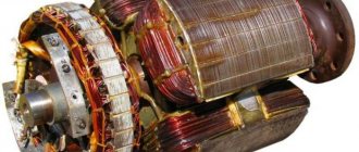
Serviceable rotor for Bosch angle grinder GWS6-100/GWS 850 MAX. Photo 220Volt
The rotor is one of the most complex structural elements of an angle grinder. At the same time, it is in a constant rotating state, which creates additional problems in maintaining normal operating conditions. Therefore, the reason for the malfunction of the angle grinder may be a broken anchor. However, you should not throw away such an angle grinder; you can actually do the repairs yourself . Rewinding failed reels is not such a difficult task and many people are quite capable of doing it.
Diagnostics
Before starting repairs, you should diagnose the failed angle grinder . This will allow you to determine the true reason why there were interruptions in the operation of the power tool and repair it at minimal cost. The electrical part of the angle grinder, which includes the rotor, is diagnosed according to certain rules using available instruments. Information on how to check the rotor for serviceability can be obtained from the link “Checking the continuity of the armature of an angle grinder with your own hands.”
Features of a sequential excitation (SF) motor
In electrical devices that use a series-excited winding, a series connection to the armature winding is provided. Consequently, the current of the PV winding is equal to the current characteristic of the armature. At light loads, the last parameter is much less than the nominal one, and the magnetic system is unsaturated, the electromagnetic torque is proportional to the square of the current in the armature winding.
Varying the load upward implies proportional saturation. When operating the units, it is necessary to take into account the fact that units characterized by sequential excitation cannot be connected to the power supply network in idle mode. This is due to the fact that with a small load volume, the rotation frequency of the anchor element quickly and sharply increases. It is for this reason that such motors do not use a belt drive, because if it breaks, the unit automatically goes to idle.
But there are exceptions to the rules - motors with power up to 200 W inclusive. They can be used in idle mode as long as the volume of mechanical/magnetic losses is commensurate with the nominal characteristics of the power unit.
Required Tools
Multimeter Zubr. Photo 220Volt
To rewind the rotor windings, the following basic materials, tools and accessories .
1. Rewinding can be done in two ways :
- completely manually without the use of any equipment;
- Productivity increases greatly with the use of simple devices.
2. Multimeter or other instruments.
3. The user must be able to operate an electric soldering iron.
4. The presence of a winding wire, the diameter of which must correspond to the failed wire.
5. Electrical insulating cardboard or other similar material.
6. Sandpaper, textolite plates, soft wood and other materials for performing auxiliary work.
7. Epoxy resin or other impregnating varnish.
8. Other plumbing tools : hammers, a set of screwdrivers, hacksaw blades, sharp objects, such as a well-sharpened knife, chisels and other tools.
Winding check
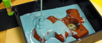
In most cases, the problem can be detected by its appearance and characteristic odor (see Figure 1). If the fault cannot be determined empirically, we proceed to diagnostics, which begins with a continuity test. If one is found, the engine is disassembled (this process will be described separately) and the connections are thoroughly inspected. When no defect is detected, a break can be established in one of the coils, which requires rewinding.
If the continuity test does not show a break, you should proceed to measuring the winding resistance, taking into account the following nuances:
- the insulation resistance of the coils to the housing should tend to infinity;
- for a three-phase drive, the windings must show the same resistance;
- For single-phase machines, the resistance of the starting coils exceeds the readings of the working windings.
In addition, it should be taken into account that the resistance of the stator coils is quite low, so to measure it it makes no sense to use devices with a low accuracy class, such as most multimeters. You can correct the situation by assembling a simple circuit using a potentiometer with the addition of an additional power source, for example a car battery.
Circuit for measuring winding resistance
The measurement procedure is as follows:
- The drive coil is connected to the circuit presented above.
- The potentiometer sets the current to 1 A.
- The coil resistance is calculated using the following formula: , where RK and UPIT were described in Figure 2. R is the resistance of the potentiometer, and is the voltage drop across the measured coil (shown by a voltmeter in the diagram).
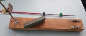
It is also worth talking about a technique that allows you to determine the location of the interturn short circuit. This is done as follows:
The stator, freed from the rotor, is connected through a transformer to a reduced power supply, having previously placed a steel ball on it (for example, from a bearing). If the coils are working, the ball will move cyclically along the inner surface without stopping. If there is an interturn short circuit, it will “stick” to this place.
Steel ball testing
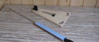
Laying diagram, winding Interskol 230, Makita 9558HN or 9558BN and other models
The order of winding the rotor windings depends on the number of slots in the rotor core and the commutator lamellas. The parameters that determine the location of the winding wire on the rotor include winding direction and pitch . The rotation of the spindle shaft (right or left) is precisely related to the choice of which direction the wire is laid. When performing rotor repairs, it is necessary to record the above data of the burnt winding.
Important : visually identify the topmost coil and start unwinding the end from it in order to determine the layout of the winding wire. Maintaining the old pattern is a determining factor in successful anchor repair.
The number of turns and the diameter of the wire are fixed after removing the front part of the failed winding, which will allow you to carefully remove the complete bundle of wire located in the groove.
Most of the used grinders, regardless of the model (Interskol, Makita and others), are structurally made with 24 slats and a core with 12 grooves. The winding pitch is chosen to be 6.
12 grooves and 24 slats
Rotor for INTERSKOL USHM-2300M, HAMMER. Photo 220Volt
The rotor winding with such design parameters is performed as follows.
- The direction of the winding is set (usually clockwise when viewed from the commutator side).
- Insulation made of electrical cardboard and other similar material is installed in the cleaned grooves . The winding wire is soldered to lamella No. 1 in accordance with the old installation scheme.
- The wire is placed in groove No. 1 opposite the lamella indicated by the first number and, according to the winding pitch, is directed into groove No. 6 and returning back. The number of such layings corresponds to the size of the winding turns.
- A circuit with 12 grooves and 24 lamellas is built after soldering the middle of the winding to lamella No. 2 and continuing to wind the winding wire into the same groove. The required number of turns is maintained and soldering is carried out to lamella No. 3. This is how the first complete reel is obtained.
- Next, winding is carried out in slots No. 2 and No. 7 , soldering the middle of the winding to lamella No. 4 and the end of the winding to lamella No. 5.
- By winding the coils using the above method, the last of which ends on lamella No. 1, all 12 grooves and 24 lamellas will be involved in the laying pattern.
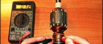
How to quickly check the commutator motor mechanism for malfunction
Checking the element - armature , which is the main part of the commutator motor, is carried out in stages. To carry out performance testing, you need to prepare a screwdriver and a multimeter. Monitoring your condition at home can save you money.
Nuance: To improve the quality of checking the armature winding for a faulty commutator motor , it would be a good idea to buy an inexpensive device. The latter allows for in-depth monitoring of the armature core .
The initial stage is a thorough visual inspection of electrical equipment. There are situations when electrical equipment still works, but with deterioration in nominal characteristics. The latter may be a consequence of an interturn short circuit ; the result is that the part “burns.” This is easy to determine - you don’t even need to disassemble the case.
Some signs, but not the main ones, are:
- strong sparking during operation of the electric motor - noticed on the traction motor commutator ;
- The startup of an electric tool is accompanied by a voltage drop in the power supply network - the lighting begins to flash. Can lead to a short circuit in the entire facility;
- when trying to start the electric motor, sharp jerks appear;
- burnt smell of winding mechanism;
- the tool cannot reach its rated power.
But it is worth noting that the above-mentioned signs show not only a breakdown of the armature of the collector unit - the engine . All of the above may indicate mechanical and electrical wear of the motor assembly brushes. Worn out, collapsed brushes are the main cause of power plant failure. Replacing them with new ones and cleaning the unit from plaque will extend the service life of power equipment.
When examining the part, there should be no traces of burning, paper, or blackening on it. The mentioned nuances are consequences of a short circuit or combustion. Prolonged presence of dust and dirt provokes a deterioration in the performance of the entire installation as a whole. Therefore, the aspect of cleanliness and maintenance must be given due attention, otherwise:
- premature wear of elements increases - scale and carbon deposits negatively affect the quality of work;
- the resistance of the internal parts of the electrical unit to negative environmental influences decreases.
Is the brush mechanism intact? Then the fault lies in the CD mechanism. But there are situations in which a power tool does not show signs of life - it does not start, does not react in any way to an attempt to turn it on. Let's move on to the next stage.
Complete dismantling of the tool body and disassembly
If the brushes are in order, but the cause of the breakdown cannot be determined, then disassembly of the electrical equipment will be required. The problem may lie in the internal parts of the commutator motor. First you need to pick up a screwdriver - a licked thread will not bring anything good.
The equipment has fasteners of various sizes. In order not to make a mistake, you need to remember, or better yet, sketch the bolt placement diagram. For better memory, you can take photographs of each stage of the work. This will prevent problems with the assembly of the power tool.
Household electrical appliances do not always have a complex design, and therefore the disassembly process is not particularly complex, which cannot be said about industrial electrical installations. Technical diagnostics and repair of the latter require advanced qualifications of specialists and the availability of professional testing equipment.
Preliminary preparation of the collector armature
Completed dismantling is not the final operation. The element must be prepared for further inspection. Preliminary measures will ensure the highest quality diagnostics of the component. This procedure is simple and consists of completely cleaning the slats from plaque.
The fact is that during active use, particles of work products accumulate on the surfaces of parts. This is especially true for electric motors that have been used for a long time. Plaque prevents the correct passage of current and load distribution throughout the collector complex.
Preparation is optional. But it will improve the quality of the result. Cleaning involves the use of rags and an alcohol solution. Removal of carbon deposits occurs through the action of fine-grained sandpaper. Do it carefully - any remnants of an abrasive tool will aggravate the situation with the performance of the commutator motor. Therefore, after removing carbon deposits, you need to remove traces of abrasive action with sandpaper.
Note : The mechanism must be cleaned carefully without damaging the winding . The ingress of abrasive particles and broken lamellas are aspects that increase the likelihood of an interturn short circuit in a commutator motor.
Complex processing
Processing of composite shafts is carried out in strict compliance with the second class of accuracy. The final operation is additional grinding, which does not allow the presence of transverse scratches or burrs. The mentioned abrasives significantly damage the integrity of the surface layer of the shaft.
Close attention is paid to the transition fillets - they need to be polished to a shine. This ensures uninterrupted operation of both the individual device and the entire installation as a whole. The coefficient of compression of the surface of the shaft and bushing is also reduced - necessary for an accurate fit of the anchor bushing to the shaft. In connection with the latter, diameter ledges are made along the seats.
Visual inspection before testing
Here you need to carefully inspect the manifold and the CD part. If the latter has significant depletion, then repair will not help, only replacement is relevant. The presence of a large accumulation of carbon deposits on the windings of the device and its contacts is a sign of a deep malfunction of the part. There are several ways to solve this. The first is complete rewinding, according to the winding diagram of the armature of the commutator mechanism - the engine . It will take a long and painful time to do, and the second is installing a new part. The choice is, of course, yours.
Fast and high-quality inspection - emphasis on specific details, allowing you to comprehensively determine the breakdown of elements. Pay attention to elements such as:
- collector lamellas are parts on which carbon deposits often accumulate. Constant contact wears them out, and therefore if there is significant wear, there is a high probability of further motor failure;
- armature windings – breaks, traces of interturn short circuit and conductor burning;
- contact elements of the power unit - windings are connected to the lamellas by soldering. These places must be carefully checked for integrity. Breakdowns of contacts are fraught with deterioration in the performance of the electric motor.
After completing the visual inspection of the part, you can begin using the diagnostic equipment.
Monitoring performance with a radio multimeter
The use of a measuring device is a mandatory aspect. Without it, alas, it will be almost impossible to correctly determine the problem and the cause of the malfunction. Directly using a multimeter is divided into several stages, usually there are two. The first involves checking for the presence of a breakdown. How it's done:
- The device is set to check the electrical circuit, accompanied by a sound indication;
- one probe of the device acts on each part, and the second – on the body of the power element.
The second stage involves measuring the resistance that arises between adjacent windings. This is done very easily - the multimeter is set to resistance detection mode at the minimum range - usually set to 200 Ohms. Probes are the contact parts of a radio-technical device and are placed on the lamellas of the commutator.
The device reads the resistance parameters and transfers them to the screen. Next, the measured characteristics are recorded (it is better to write them down so as not to forget). The resistance should be the same between all lamellas. If this is not the case, then the commutator motor mechanism is faulty. Lack of resistance is a factor confirming a performance problem.
Diagnostics for determining interturn short circuit (MF)
One of the main causes of breakdowns is a short circuit between the turns. It is formed due to increased load on the motor, exceeding the maximum permissible parameter. The windings of the stationary mechanism - the stator - heat up, the increased temperature conditions trigger degenerative insulation processes, and as a result, MF occurs. Incorrect operating specifications lead to a significant increase in the load on the equipment.
Tip : Before using the motor, read the passport information. It indicates acceptable parameters under which the application will not have a destructive effect.
Excessive load is formed due to breakdown of the mechanical part. Bearings often jam, which leads to short-circuiting of the armature coil turns. This problem may arise due to manufacturing defects or be a consequence of poor-quality repair work.
Determine MH:
- check the stator temperature - uneven heating confirms a breakdown;
- measure the load of each phase. The difference may be a sign of a broken element.
As in the case of continuity testing, the MH is checked with a multimeter or megger. There is a more accurate method - using a transformer using step-down technology:
- Three phases of the transformer are connected to the stator;
- Next, the ball is thrown into the stator. If the ball runs in a circle, then everything is fine, if not, it is magnetized - a short circuit.
Instead of a ball, a plate is used. In the place where the MS occurs, vibration occurs. If the armature is working properly, the element is simply magnetized to the iron. Don't forget about grounding.
The MF is easily determined using a specialized device, which is a transformer with a cut-out core. Placement in the slot causes the component to function as a secondary winding. During an interturn short circuit, the plate located at the top vibrates or is magnetic to the body. After eliminating the problem, it is necessary to re-check using the above method.
How to balance electric motors
Balancing of armature rotors is carried out in two ways - static and dynamic. Static balancing
performed with the engines stopped using simple equipment or special scales. Having determined the location of the center of mass, the specialist only has to calculate the mass required for adjustment and determine the location for its installation. The more experienced the specialist, the higher the accuracy of such balancing. All work, including measuring, is carried out at rest. After completion of the procedure, repeated measurements and a control start of the engine are performed.
Dynamic balancing
anchors are made using special equipment with the engine running or the shaft spinning. A so-called balancing machine is used here. It detects imbalances in rotation, allowing balancing to be carried out with maximum precision.
Dynamic balancing of electric motor rotors makes it possible to identify static imbalance remaining after static balancing. That is why the latter is used only for serious violations. For example, this method is used when working with low-power electric motors with a rotation speed of no higher than 1000 rpm. Here the slight imbalance is almost unnoticeable. If the engine rotates at a speed above 1000 rpm, dynamic balancing is activated - more accurate. It allows you to identify even the most insignificant imbalance.
The rotor of an electric motor is a complex structure with many elements, each of which has its own standard indicators. In an ideal state, the axis of inertia of the rotor should coincide with the axis of rotation, however, under the influence of external factors, prolonged use of motors can lead to their imbalance. In such conditions, timely diagnosis and troubleshooting may be the only way to extend the service life of the electric motor.
Soldering the collector plates
The slats are installed on a plastic base. They are usually erased to the very base. Only the edges remain that the brushes cannot reach.
Such a collector can be returned by soldering.
- Cut the required number of lamellas to size from a copper pipe or plate.
- When the armature of copper residues, solder it with ordinary tin and soldering acid.
- When our client is left with the lamellas soldered, do some sanding and polishing. If you don't have a lathe, use a drill or screwdriver. Insert the armature shaft into the chuck. Sand first with ratfil. Polish later with fine sandpaper. Don’t forget to clean the grooves between the slats and measure the resistance.
- There are lamellas that are not completely damaged. To return them, you need to carry out more painstaking preparation. Lightly grind the commutator to clean the records.
Source
Balancing the armature and rotor of an electric motor in Volgograd, St. Petersburg and Volzhsky
LLC "VER" balances the armature and rotor of electric motors in two ways, depending on the angular velocity. So, for quiet-running electric motors, experts use balancing in static mode
, and for high-speed electric motors, balancing
in dynamic mode
. Balancing in static mode is a complex and labor-intensive procedure that requires time, a large number of calculations and measurements. That is why we recommend that if problems arise, contact the professionals of our company, who will accurately take all the necessary measurements and perform high-quality balancing of your equipment.
You can use the services at VER LLC. In our work we use modern high-precision equipment
, allowing you to calculate the slightest traces of imbalance and eliminate them with high accuracy. The employees working on the equipment have extensive experience, thanks to which they are able to quickly find and eliminate imbalance of the center of mass in electric motors of any brand - including especially powerful and high-speed ones.
If you have determined that the rotor in your hammer drill has failed, but you do not have the funds for a new one, or you want to resurrect the part yourself, then these instructions are for you.
The design of the Makita rotary hammer is so simple that repairing Makita 2450, 2470 does not cause any particular difficulties. The main thing is to follow our advice.
By the way, almost every user with basic locksmith skills can repair a rotary hammer with his own hands.
Repair: Elimination of insulation breakdown
If the insulation breakdown was small and you found it, you need to clean the area from carbon deposits and check the resistance. If its value is normal, insulate the wires with asbestos. Apply quick-drying “Super Moment” type glue on top. It will seep through the asbestos and insulate the wire perfectly.
If you still haven’t found the location of the insulation breakdown, then try to carefully saturate the winding with impregnating electrical insulating varnish. Punched and unpierced insulation will be saturated with this varnish and become stronger. Dry the anchor in a gas oven at about 150 degrees. If this does not help, try to rewind the winding or change the armature.
Rewinding the armature
The process of replacing the winding of a commutator motor is somewhat similar, with the exception of small nuances associated with the design features. For example, the armature is sent for rewinding, not the housing, provided that the problem does not arise with the excitation coils. In addition, there are the following differences:
- For winding, a special machine with a more complex configuration is used.
- Grooving, balancing of the armature (in the final part of the process), as well as its cleaning and grinding are required.
- The manifold is cut using a special milling machine.
The above processes require special equipment; without it, rewinding electric motors is a waste of time.
Schematic diagram of the grinder
Almost every craftsman who often works with metal knows the electrical circuit of an angle grinder. The grinder is the tool most often used for cutting metal. This tool is a source of increased danger, so you should check the serviceability of the electrical and mechanical components of the structure before each use.
Schematic diagram of the grinder.
An angle grinder, which in the post-Soviet territory is called “grinder”, was the dream of every home craftsman 3-4 decades ago. 30-40 years ago, this working tool was produced by one manufacturer, the Eltos-Bulgarka plant, located on the territory of Bulgaria in the city of Plovdiv. Currently, manufacturers offer consumers various models and modifications of this tool, but the main design components have remained virtually unchanged. Most of the structural elements on different models and modifications differ only in size.