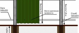
DIY drill repair
- breakdown of motor parts (stator, armature) - wear of the brushes or their burning - breakdown of the regulator and reverse switch - wear of the support bearings - poor clamping in the tool chuck.
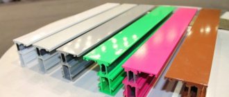
Some spare parts (switch, rotor, stator, brushes, bearings, etc.) for more popular models are bought here (but it’s better to buy through an online store, because in a regular store of this network you will like the price higher).
Replacing brushes
. The most common type of breakdown is wear of the motor brushes, which can be replaced yourself at home. Sometimes, brushes can be replaced without disassembling the drill body. For some models, it is enough to unscrew the plugs from the installation windows and install new brushes. For other models, replacement requires disassembling the housing; in this case, you must carefully remove the brush holders and remove the worn brushes from them.
Brushes are sold at all normal power tool stores, and often an extra pair of brushes is included with a new electric drill.
Don't wait for the brushes to wear down to their minimum size. This risks increasing the gap between the brush and the collector plates. As a result, increased sparking occurs, the collector plates become very hot and may move away from the base of the collector, which will lead to the need to replace the armature.
You can determine the need to replace brushes by increased sparking, which can be seen in the ventilation slots of the housing. The second way to determine this is the random jerking of the drill during operation.
Power cord
. The cord is checked with an ohmmeter, one probe is connected to the contact of the power plug, the other to the core of the cord. Lack of resistance indicates a break. In this case, repairing the drill comes down to replacing the power cord.
Electric motor diagnostics
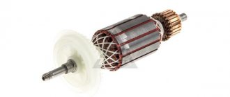
. In second place, in terms of the number of drill breakdowns, can be placed the malfunction of engine components and, most often, the armature. Failure of an armature or stator occurs for two reasons. improper operation and poor-quality coil wire. World-famous manufacturers use expensive coil wire with double insulation with heat-resistant varnish, which significantly increases the reliability of engines. Accordingly, in cheap models the quality of insulation of the winding wire leaves much to be desired. Improper operation comes down to frequent overloading of the drill or prolonged operation without breaks to cool the engine. Repairing a drill with your own hands by rewinding the armature or stator, in this case, is impossible without special tools. Only complete replacement of the element (exclusively experienced repairmen will be able to rewind the armature or stator with their own hands).
To replace the rotor or stator, it is necessary to disassemble the housing, disconnect the wires, brushes, remove the drive gear if necessary, and remove the entire motor along with the support bearings. Replace the faulty element and install the engine in place.
An armature malfunction can be determined by a characteristic smell, an increase in sparking, and the sparks have a circular motion in the direction of movement of the armature. Pronounced burnt windings can be seen upon visual inspection. But if the engine power has dropped, but there are no signs described above, then you should resort to the help of measuring instruments. ohmmeter and megohmmeter.
Features of the asynchronous motor of the angle grinder
Almost all electrical appliances used in everyday life use an asynchronous electric motor. An important advantage of this type of motor is that when the load on it changes, the speed does not change. This means that if, for example, you cut stone for a long time and without stopping with a household grinder, there will be no noticeable external signs of engine overload. The disk rotation speed will be constant, the sound will be monophonic. Only the temperature will change, but this may not be noticed if your hands are wearing gloves.
If you are not careful, an advantage can turn into a disadvantage. Asynchronous motors are very sensitive to overheating; a significant increase in operating temperature entails melting of the insulation on the rotor windings. At first, the motor will work intermittently, and then - when an interturn short circuit occurs - the motor will stop completely. If you overheat the grinder's engine several times, it is most likely that the anchor will melt. In addition, the high temperature causes the contacts connecting the wires of the primary winding to the collector to become unsoldered, which leads to an interruption in the supply of electric current.
Manual grinding machine device
The grinding tool consists of three important components:
The armature is a rotating element with a winding and creates torque of the electric motor. The stator, divided into sectors, has the same winding. The current passes through the carbon brush through the winding and enters the armature. The current then passes to other brushes until all parts of the stator are used. When electric current passes through the winding, a magnetic field constantly interacts with the stator. Thus, the electric motor is driven. There are several typical breakdowns of the grinder launcher:
Diagram of an eccentric orbital sander.
You can rewind the winding yourself, without contacting a specialist. You just need to first disassemble the device. But if you do not have complete confidence in your abilities, then contacting a specialized workshop will be the most reasonable step. First of all, the casing moves. To do this, the screw securing it is unscrewed. After this, you will be able to see all the parts of the angle grinder, with the exception of the gearbox hidden under the metal cap. The screws that secure the metal plate are unscrewed. Now all mechanical parts are clearly visible. Only after this can you proceed to rewinding the stator.
The only thing better than a well-performed repair is proper operation, in which no breakdowns occur at all. In order for the grinder to work longer, you need to follow these simple rules:
A repaired stator will allow the grinder to operate normally for a long time.
How to determine if an angle grinder's armature is faulty
Signs of a broken armature angle grinder are: increased sparking of the brushes on the motor commutator, vibration of the motor at low speeds, rotation of the working shaft in different directions. If such symptoms are present, you should stop using the tool - this is dangerous. Suspicions can be easily verified using simple tests.
Visual inspection from outside
Troubleshooting should begin with a visual inspection of the angle grinder:
- Carry out a general inspection of the instrument.
- Pay attention to the integrity of the power cord and the presence of voltage in the outlet.
- Using a voltage indicator, make sure that current is flowing to the motor commutator and the start button.
Read also: How to rivet a blind rivet without a riveter
Inspection of the device from the inside
If everything is in order with the power supply, but the angle grinder does not work, you will have to open the case to gain access to the motor. As a rule, disassembly is not difficult. But you need to follow simple rules that will help you avoid troubles during reassembly:
- Be sure to disconnect the device from the mains before disassembling.
- Remove the working disk and protective cover from the spindle.
- Open the case in a well-lit place, on a clean table surface.
- Remember the location of all parts and assemblies before disassembling. It is recommended to sketch or photograph the internal structure of the device.
- Place screws and fastening screws in a separate place so that they do not get lost.
It is best to inspect the engine under bright lighting so that all small parts are clearly visible. The armature should rotate freely around its axis; properly functioning bearings should not make any sound during operation. There should be no traces of melted wiring on the armature, the circuit windings should be intact, without breaks. You can smell the rotor. When there is an interturn short circuit, the insulating varnish burns and emits a persistent specific odor. But such a diagnosis requires some experience.
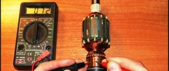
Continuity testing of circuits with a tester
If a visual inspection does not give clear results, it is recommended to continue the examination using a multimeter. Having set the mode switch to the ohmmeter position (200 Ohm range), you need to “ring” two adjacent armature lamellas with two probes. If the resistance on all turns is the same, this means that the windings are working properly. If on some pairs the tester shows a different resistance or an open circuit, there is a malfunction in this coil.
A wire break can occur between the winding and the core. You should carefully examine the junction of the coils with the collector lamellas in the lower part of the armature, and visually check the soldering of the contacts.
Checking contacts with a light bulb
If you don’t have a tester, you can get out of the situation using a simple 12-volt light bulb. The power can be any, optimally 30–40 W. The voltage from the 12 volt battery must be applied to the plug of the angle grinder by inserting a light bulb into the gap in one wire. If the armature is working properly, if you rotate the spindle by hand, the light should light without changing brightness. If the heat changes, this is a sure sign of an interturn short circuit.
If the light does not light, this may indicate the following:
- The brushes may become stuck in the non-working position. The retaining spring has worked.
- There has been a break in the supply circuit.
- There is a short circuit or break in the stator winding.
There are other diagnostic methods, but they require more sophisticated equipment, which is not usually used at home. An experienced technician will determine the breakdown with a high degree of accuracy using a “punch” or a simple transformer with a cut toroidal core and one primary winding.
Repair: Elimination of insulation breakdown
If the insulation breakdown was small and you found it, you need to clean the area of carbon deposits and check the resistance. If its value is normal, insulate the wires with asbestos. Apply quick-drying “Super Moment” type glue on top. It will seep through the asbestos and insulate the wire well.
If you still haven’t found the location of the insulation breakdown, then try carefully soaking the winding with impregnating electrical insulating varnish. Punched and unpierced insulation will be saturated with this varnish and become stronger. Dry the anchor in a gas oven at about 150 degrees. If this does not help, try rewinding the winding or changing the armature.
Soldering the collector plates
The slats are mounted on a plastic base. They can be erased to the very base. Only the edges remain that the brushes cannot reach.
Such a collector can be restored by soldering.
- Cut the required number of lamellas to size from a copper pipe or plate.
- After you have stripped the armature of copper residues, solder it with regular tin and soldering acid.
- When all the lamellas are soldered, sand and polish. If you don't have a lathe, use a drill or screwdriver. Insert the armature shaft into the chuck. First, sand with a file. Then polish with grit sandpaper. Don't forget to clean the grooves between the slats and measure the resistance.
- There are lamellas that are not completely damaged. To restore them, more thorough preparation is necessary. Lightly grind the commutator to clean the plates.
Sometimes even a reliable electric drill breaks down.
As statistics show, failures occur not so much in its mechanical part as in its electrical part. But if a lot of advice on restoring an electrical cord, replacing worn brushes, a damaged switch or eliminating other simple faults in household appliances has been published, including on the pages of the “Model Designer” (see, for example, No. 9'95.6'96.2 '97), the same cannot be said about more complex types of repairs. In particular, there is a clear lack of materials on the features of maintenance and feasible (in a home workshop) repair of the rotor of commutator motors, usually installed in drills, impact wrenches and other hand-held power tools. Unfortunately, there are many of these features. It is hardly possible to understand them without understanding the structure and operating principle of commutator motors (Fig. 1). It is also worth remembering that, in accordance with the laws of physics, a force F acts on a conductor with current I in a magnetic field of intensity H, the direction of which is determined by the so-called left-hand rule. Moreover, judging by the simplified diagram, the greatest torque is created when the current-carrying coil is located exactly between the poles of the electromagnet.
However, a real motor develops maximum power when the working turn (loop winding) is positioned at a leading (commutation) angle, which for a drill is approximately 45°. In this case, the alternating current after the electromagnet enters brush A, passes to lamella A of the commutator and then, along the turns of the loop section, to lamella B. But the latter is electrically connected to the antipode - lamella B', from which the current through brush B goes into the power supply network .
Rice. 1. Scheme of operation and simplified design of the commutator motor:
1 - south pole of the stator electromagnet; 2 - rotor rotor winding (“+” is a conventional image of the current directed towards the plane of the drawing, and “-” - away from it); 3 - north pole of the stator electromagnet; 4 - copper-graphite brush A; 5 - lamella A; 6 — lamella B; 7 — lamella B'; 8 — copper-graphite brush B; 9 - rotor; a is the advance (switching) angle; H—magnetic flux; F is the pushing force of a current-carrying conductor in a magnetic field (determined by the left-hand rule); Fa is the force acting on the loop winding taking into account the commutation angle; i—electric current; w is the angular speed of rotation of the rotor
Single-phase commutator motors of most hand-held machines are non-reversible, that is, they rotate only in one direction, determined by a specific switching circuit. The brushes are located with a shift of the geometric neutral by one or two commutator divisions. The shear angle is specified experimentally based on the minimum sparking at the working surface of the commutator at rated load for the required direction of rotation. In reversible motors, which are usually used to drive thread-driving machines, the brushes are installed at a geometric neutral.
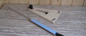
The runout of the commutator surface is monitored during engine maintenance using a dial indicator when slowly turning (manually!) the armature or rotor of electrical machines. If the engine is in a disassembled state, then the armature or rotor is installed in the centers and also rotated. When taking measurements, the indicator leg is set perpendicular to the surface of the collector. The runout value (and it, as a rule, should not exceed 0.05-0.06 mm) is determined by the difference between the largest and smallest readings of the device.
Profile control is also a very important element in determining the technical condition of the reservoir. This operation is performed visually, paying attention to the depth of the micanite spacers between the lamellas, which should be within 0.3-0.5 mm.
Soldering failures or breaks are usually determined by measuring the voltage drops at the junction of the collector plates with the armature winding (Fig. 2). The connection of the terminals of the loop windings with the corresponding collector plates is considered satisfactory if the voltage drops at the soldering points do not differ by more than ± 10 percent of the average value.
Rice. 2. Scheme for checking the electrical connection of the collector plates with the loop windings of the rotor:
1 — electric probe (4 pcs.); 2 - collector with lamellas; 3 - loop winding being tested; 4 - pointer millivoltmeter; 5 - galvanic battery; 6 - variable resistor; the values of elements 4-6 are specified during preliminary configuration of the circuit
It happens that the windings themselves are so bad that it is advisable to replace the entire rotor (armature) with a new one. Well, if this is not possible, you have to rewind even in a home workshop. This is a very troublesome matter; To carry it out, you need to have the appropriate tools, devices, consumables and, of course, a diagram (preferably with a pie diagram) of the winding.
In what cases can you save an anchor and restore it yourself?
If damage to the armature is determined with guaranteed accuracy, the part must be removed from the electric motor. Disassembling the motor must be done with special care, after removing the brushes and disconnecting the power terminals. The rotor is removed along with the support bearings and the motor cooling impeller; they form a single whole with it.
If most of the wiring in the armature is damaged and the balancing is disrupted as a result of overheating, it is better to replace it entirely. An imbalance is indicated by increased vibration and an uneven hum when the mechanism operates.
How to rewind an anchor - step-by-step instructions
If the balancing of the armature is not disturbed, and the problem is only in damaged windings, then such an armature can be restored independently by rewinding the coils. Rewinding a rotor at home requires a lot of patience and accuracy.
The technician must have skills in working with a soldering iron and instruments for diagnosing electrical circuits. If you are unsure of your abilities, it is better to take the engine to a workshop for repairs or replace the entire armature yourself.
To rewind the anchor yourself you will need:
- wire for a new winding. A copper core with a diameter exactly matching the old conductor is used;
- dielectric paper for insulating the winding from the core;
- varnish for filling coils;
- soldering iron with tin-lead solder and rosin.
Before rewinding, it is important to count the number of turns of wire in the winding and wind the same amount of new conductor onto the coils.
The rewinding process consists of the following steps:
- Dismantling old windings. They must be carefully removed without damaging the metal body of the armature. If any burrs or damage are found on the body, they must be smoothed out with a file or sanded with emery. Sometimes, to completely clean the body of slag, craftsmen prefer to burn it with a torch.
- Preparing the collector for connecting a new wire. There is no need to remove the manifold. You should inspect the lamellas and measure the resistance of the contacts in relation to the housing with a megger or multimeter. It should be no more than 0.25 MOhm.
- Removing old wiring on the manifold. Carefully remove the remaining wires and cut grooves in the contacts. In the future, the ends of the coil wires will be inserted into the grooves.
- Installation of sleeves for anchors. The sleeves are made of dielectric material 0.3 mm thick, for example, electrical cardboard. Cut a certain number of sleeves and insert them into the grooves of the cleaned anchor.
- Rewinding reels. The end of the new conductor is soldered to the end of the lamella and wound in successive circular movements, counterclockwise. This laying is called “laying to the right.” Winding Repeat for all coils. Near the collector, tie the wires together with a thick thread of cotton fabric (it is prohibited to use nylon, as it melts when heated).
- Checking the winding quality. After laying all the windings, check with a multimeter for the absence of interturn short circuits and possible breaks.
- Finishing processing. Treat the finished coil with varnish or epoxy resin to secure the winding. In factory conditions, the impregnation is dried in special ovens. You can do this at home in the oven. As an option, use quick-drying varnishes for impregnation, applying the coating in several layers.
Read also: DC motor 220V
The procedure for disassembling, repairing, and assembling a hammer drill rotor
Here is the sequence for repairing a rotor with a short circuit in the windings:
- Trimming the front part of the windings.
- Removing the collector and frontal parts and measuring the diameter of the wire being removed.
- Removal and cleaning of groove insulation, counting the number of turns along the sections.
- Selection of a new collector.
- Installation of a new collector.
- Production of blanks from insulating material.
- Installing sleeves into grooves.
- Winding the anchor.
- Wiring of conclusions.
- Heat shrink process.
- Shell reservation.
- Shell impregnation.
- Collector impregnation
- Milling the slots of the commutator lamellas
- Balancing
- Cleaning and grinding the rotor.
Now let's look at everything in order.
Stage I
At the first stage, the collector must be removed from the armature. The commutator is removed after boring or sawing the end parts of the winding.
Cutting the frontal parts of the winding
If you are repairing a rotary hammer yourself, you can cut the frontal parts of the winding using a hacksaw. Clamping the rotor in a vice through the aluminum spacers, saw the frontal parts of the winding in a circle, as shown in the photo.
Stage II
To release the collector, the latter must be held by the lamellas with a gas wrench and turned along with the cut front part of the winding, turning the wrench in different directions.
The second method of removing the manifold and frontal parts
At the same time, clamp the rotor in a vice through soft metal spacers.
Replacing the anchor yourself at home
Practice shows that if you decide to replace the armature of an angle grinder, then it is best to change it together with the support bearings and the engine cooling impeller.
To replace you will need:
- New angle grinder anchor. Must match your model. Interchange with other models is not permitted.
- Screwdrivers, wrenches.
- A soft brush and cloth for wiping the mechanism.
How to remove an anchor
Replacing the anchor begins with disassembling the angle grinder. The following steps are performed:
- Use a screwdriver to unscrew the brush units on both sides. The brushes are removed.
Video: replacing bearings on an angle grinder
How to put an anchor in place
To install a new angle grinder anchor in place, you should take a new part, and then assemble the tool in the reverse order. The sequence of actions is as follows:
- A fixation disk is installed on the armature shaft.
- The bearing is installed using the pressing method.
- The small gear is fitted and secured with a retaining ring.
- The anchor is inserted into the gearbox housing, and the docking holes are aligned.
- The gearbox mounting bolts are tightened.
- The anchor with the gearbox is inserted into the body of the angle grinder and fixed.
- The brushes are deposited in their places and closed with lids.
After completing these steps, the grinder is ready for work. The anchor has been replaced.
Video: how to check an angle grinder
An ancient Sufi wisdom says: “A smart person is one who is able to come out of a difficult situation with dignity. But the one who does not find himself in such a situation is wise.” By following the rules for operating household appliances and preventing the motor from overheating, you can avoid breakdowns and troubles in the operation of the angle grinder. Keeping and storing the tool clean and dry will prevent its mechanisms from contamination and oxidation of current-carrying elements. Timely maintenance of the tool is guaranteed to eliminate unpleasant surprises during operation.
In many household devices and home-made structures, low-power electric machines are used as a drive. Despite the high reliability of electric motors, their failure for a number of reasons is not uncommon. Given the relatively high cost of these devices, it is more practical to repair them rather than replace them. We suggest considering the possibility of rewinding electric motors at home.
Features of repairing an asynchronous machine
Engine problems of any type can be mechanical or electrical in nature. In the first case, strong vibration and characteristic noise may indicate a malfunction; as a rule, this indicates problems with the bearing (usually in the end cover). If the malfunction is not corrected in time, the shaft may jam, which will inevitably lead to failure of the stator windings. In this case, the thermal protection of the circuit breaker may not have time to operate.
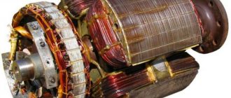
“Burnt” wires of the stator winding
Based on practice, in 90% of failures of asynchronous machines, problems arise with the stator winding (break, interturn short circuit, short circuit to the frame). In this case, the short-circuited armature, as a rule, remains in working condition. Therefore, even if the damage is mechanical, it is necessary to check the electrical part.
Rewinding the stator of a grinding machine
Nowadays, rewinding the stator of an angle grinder can be done independently. To do this, you need to stock up only with the necessary knowledge. If the master has the necessary tools, skills in carrying out repair work and a certain amount of knowledge in the field of electrical engineering, the question of how to fix the malfunction of this tool with your own hands can be solved quite easily.
Stator winding diagram.
Winding check
In most cases, the problem can be detected by its appearance and characteristic odor (see Figure 1). If the fault cannot be determined empirically, we proceed to diagnostics, which begins with a continuity test. If one is found, the engine is disassembled (this process will be described separately) and the connections are thoroughly inspected. When no defect is detected, a break can be established in one of the coils, which requires rewinding.
If the continuity test does not show a break, you should proceed to measuring the winding resistance, taking into account the following nuances:
- the insulation resistance of the coils to the housing should tend to infinity;
- for a three-phase drive, the windings must show the same resistance;
- For single-phase machines, the resistance of the starting coils exceeds the readings of the working windings.
In addition, it should be taken into account that the resistance of the stator coils is quite low, so to measure it it makes no sense to use devices with a low accuracy class, such as most multimeters. You can correct the situation by assembling a simple circuit using a potentiometer with the addition of an additional power source, for example a car battery.
Circuit for measuring winding resistance
The measurement procedure is as follows:
- The drive coil is connected to the circuit presented above.
- The potentiometer sets the current to 1 A.
- The coil resistance is calculated using the following formula: , where RK and UPIT were described in Figure 2. R is the resistance of the potentiometer, and is the voltage drop across the measured coil (shown by a voltmeter in the diagram).
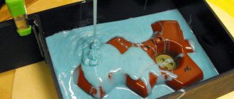
It is also worth talking about a technique that allows you to determine the location of the interturn short circuit. This is done as follows:
The stator, freed from the rotor, is connected through a transformer to a reduced power supply, having previously placed a steel ball on it (for example, from a bearing). If the coils are working, the ball will move cyclically along the inner surface without stopping. If there is an interturn short circuit, it will “stick” to this place.
How to call
For high-quality diagnostics of the angle grinder stator, you should completely disassemble the power tool in order to remove all other structural elements, including the rotor, to ensure free access to all its parts. At the initial stage, it is necessary to perform a visual inspection. For a more complete picture, you should definitely check for defects using electrical instruments. What devices and how to ring the stator of an angle grinder are described in detail at the link “How to ring the stator of an angle grinder.”
Features of repair of commutator drives
This type of electric machine is more likely to experience mechanical failures. For example, brushes worn out or commutator contacts clogged. In such situations, repairs come down to cleaning the contact mechanism or replacing graphite brushes.
Read also: Laying signal tape over the cable
Testing the electrical part comes down to checking the resistance of the armature winding. In this case, the probes of the device are applied to two adjacent contacts (lamellas) of the collector, after taking readings, measurements are taken further in a circle.
Checking the armature winding of a commutator motor
The displayed resistance should be approximately the same (taking into account the instrument error). If a serious deviation is observed, then this indicates that there is an interturn short circuit or open circuit, therefore, rewinding is necessary.
Where to begin?
Since the structure of the rotary hammer is simple, the repair of the makita rotary hammer must begin with its disassembly. It is best to disassemble the hammer drill according to the already proven procedure.
Algorithm for disassembling a hammer drill:
- Remove the back cover on the handle.
- Remove the electric carbon brushes.
- Disconnect the mechanical block housing and the stator housing.
- Disconnect the rotor from the mechanical unit.
- Remove the stator from the stator housing.
Remember, the stator housing is green, the mechanical unit housing with the rotor is black.
Having disconnected the rotor from the mechanical unit, we proceed to determine the nature of the malfunction. Rotor Makita HR2450 pos.54; article 515668-4.
How to find a short circuit in the rotor
Since you are repairing rotary hammers yourself, you need an electrical diagram for a Makita 2450, 2470 rotary hammer.
Makita 2470, 2450 rotary hammers use AC commutator motors.
Determining the integrity of a brushed motor begins with a general visual inspection. The faulty rotor pos. 54 shows traces of burnt windings, scratches on the commutator, and traces of burning on the commutator lamellas. A short circuit can only be detected in a rotor whose circuit does not have an open circuit.
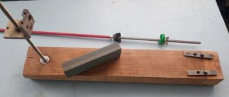
To determine a short circuit (SC), it is best to use a special device IK-32.
Checking the armature for short circuit using a homemade indicator
After making sure, using the specified device or a homemade device, that the rotor has a short circuit between the turns, proceed to disassemble it.
Rotors before disassembly
Before disassembling, be sure to fix the winding direction. This is done very simply. Looking at the end of the rotor from the commutator side, you will see the winding direction. There are two winding directions: clockwise and counterclockwise. Record and write down, you will definitely need this data when winding yourself. The rotor of the Makita rotary hammer has a clockwise winding direction, right.
Motor winding data
This is a reference data, so the most reliable way to obtain this information is to consult the appropriate sources. This data can also be provided in the product passport.
You can find advice online that recommends manually counting the turns and measuring the diameter of the wire when rewinding. It's a waste of time. It is much easier and more reliable to find all the necessary information using the engine markings, which will indicate the following parameters:
- rated operating characteristics (voltage, power, current consumption, speed, etc.);
- number of wires for one slot;
- Ø wire (as a rule, insulation is not taken into account in this indicator);
- information on the outer and inner diameter of the stator;
- number of grooves;
- with what step the winding is performed;
- rotor dimensions, etc.
Below is a fragment of a table with winding data for electric machines of type 5A.
Example of a table with winding data
Winding diagram, how to choose wire thickness
The stators of angle grinders have a very similar design and differ in the size of the parts in which the magnetic flux is formed, the number of turns in the windings and the diameter of the wire. The standard connection diagram for grinders is shown in the following figure.
Here L1 and L2 denote the stator coils.
The burnt winding is removed, and it is necessary to collect information about the old coils : determine the number of turns, wire diameter, beginning, end of the winding and the required direction during rewinding work. The number of turns is determined by direct counting of wires after cutting the failed coils.
The diameter of the wire should match the windings being replaced as closely as possible. Therefore, the most suitable measuring tool is a micrometer with a measurement accuracy of up to 0.01 mm. The measurement is carried out on the surface of the wire of the burnt coil, stripped of the insulating coating.
Step-by-step instructions for rewinding an electric motor with your own hands
It is necessary to immediately warn that without special equipment and operating skills, rewinding reels will most likely be a useless task. On the other hand, negative experience is also experience. Understanding the complexity of a process is the best explanation of its cost.
The first stage is dismantling
We present an algorithm of actions for asynchronous machines, it is as follows:
- Disconnect the drive from the network (380 or 220 V).
- We remove the electric motor from the structure where it was installed.
- Remove the rear cooling fan shroud.
- We dismantle the impeller.
- We unscrew the fastening of the end covers, and then remove them. It is advisable to start from the front part; after dismantling it, the rotor will easily “come out” from the rear cover.
- We take out the rotor.
This process can be greatly simplified if you use a special device - a puller. With its help, it is easy to free the motor shaft from a pulley or gear, and also remove the end covers.
Puller for dismantling
We will not provide instructions for disassembling a commutator motor, since it is not particularly different. The structure of an electric machine of this type can be found on our website.
Stage two - removing the winding
The sequence of actions is as follows:
- Using a knife, remove the bandage fasteners and insulating coating from the wire connections. Some instructions recommend recording the wiring diagram, for example, by taking a photograph. There is no particular point in doing this, since this is reference information and finding it out by engine brand is not a problem.
- Using a chisel, knock off the tops of the wires from each end of the stator.
- We release the grooves using a punch of the appropriate diameter.
- We clean the stator from dirt, soot, and impregnation varnish.
Stator freed from winding
At this stage, we recommend stopping, picking up the case and taking it to specialists. Independent dismantling will reduce the cost of restoration work. As mentioned above, without special equipment it is quite difficult to rewind reels efficiently. To understand the complexity of the process, we will describe its technology, which will make the choice easier.
Stator rewinding (final phase)
The process consists of the following steps:
- Installation of insulators in each groove (sleeving).
- The thickness of the material and its characteristics are selected from the reference book.
- Winding data is determined by motor brand.
- A special machine is used to wind the required number of turns of loose coils. You can find photos and parameters of homemade manual machines on the Internet, but the quality of their work is quite questionable.
Bulk Winding Machine - The coil groups are placed in the grooves, after which they are tied and connected. These processes are quite complex and are performed manually.
- Impregnation is carried out. To do this, the body is heated to a temperature of 45°C - 55°C and completely immersed in a container with impregnating varnish. It makes no sense to varnish the wires, since in this case there will still be voids.
- After impregnation, the body is placed in a special chamber, where drying is carried out at a temperature of 130-135°C.
- Final testing of the coils with an ohmmeter.
- Assembly and test run (if only the body, but also other parts and fasteners were transferred for repair).
If only the body was submitted for restoration, we recommend checking the coils before turning on the motor.
Preparation for repairs and necessary tools
To rewind the stator you will need special tools:
The first and most important stage is cleaning the stator from contamination. The old winding is removed from the slots. All this can be done with a steel brush. Cleaning is carried out manually using steel brushes and electric drills. It is also necessary to remove the old insulation. To make the task easier, you can use transformer oil. You need to warm it up a little and lower the launcher into it. This measure will soften the damaged insulation and make it easier to remove. A weak caustic solution (temperature – 80ºС) mixed with compressed air is also used for cleaning.
After treatment, the stator must be rinsed well with water and dried. The condition of the stator and steel packages must be thoroughly checked. Then the pins tightening the core are tightened, and the grooves are cleaned of burrs. Insulation resistance is measured using a megger. Parts of the core, pressure washers and grooves are varnished. Washers and grooves must be insulated.
An accompanying note that displays basic data can make further work easier:
Next, the remaining winding is removed and a new one is wound. There is a special template for making the winding. It is mounted on an axis holding 2 large metal plates.
Rewinding the armature
The process of replacing the winding of a commutator motor is somewhat similar, with the exception of small nuances associated with the design features. For example, the armature is sent for rewinding, not the housing, provided that the problem does not arise with the excitation coils. In addition, there are the following differences:
- For winding, a special machine with a more complex configuration is used.
- Grooving, balancing of the armature (in the final part of the process), as well as its cleaning and grinding are required.
- The manifold is cut using a special milling machine.
The above processes require special equipment; without it, rewinding electric motors is a waste of time.