General information about cable and wire
When working with conductors, it is necessary to understand their designation.
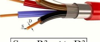
There are wires and cables that differ from each other in their internal structure and technical characteristics. However, many people often confuse these concepts. A wire is a conductor that has in its design one wire or a group of wires woven together and a thin common insulating layer. A cable is a core or a group of cores that has both its own insulation and a common insulating layer (sheath). Each type of conductor will have its own methods for determining cross sections, which are almost similar.
Conductor materials
The amount of energy that a conductor transmits depends on a number of factors, the main one of which is the material of the current-carrying conductors. The following non-ferrous metals can be used as the core material of wires and cables:
- Aluminum. Cheap and lightweight conductors, which is their advantage. They are characterized by such negative qualities as low electrical conductivity, a tendency to mechanical damage, high transient electrical resistance of oxidized surfaces;
- Copper. The most popular conductors, which have a high cost compared to other options. However, they are characterized by low electrical and transition resistance at the contacts, fairly high elasticity and strength, and ease of soldering and welding;
- Aluminum copper. Cable products with aluminum cores coated with copper. They are characterized by slightly lower electrical conductivity than their copper counterparts. They are also characterized by lightness, average resistance and relative cheapness.
Some methods for determining the cross-section of cables and wires will depend specifically on the material of their conductor component, which directly affects the throughput power and current strength (method of determining the cross-section of conductors by power and current).
Features of electrical wires
With all the variety of cable products and a huge selection of wires for laying electrical networks, there are selection rules. It is not necessary to memorize all brands of cables and wires; you need to be able to read and decipher their markings. First, it’s worth figuring out the difference between a wire and a cable.
Wire – A conductor used to connect two sections of a circuit. May have one or more conductive wires. The veins can be:
- naked;
- isolated;
- single-core;
- stranded.
Bare lines are used where touching live wires is impossible. In most cases they are used for overhead power lines.
The insulating coating is used in one or two layers. Wires that have two or three conductors in double insulation are confused with a cable. The confusion occurs due to the fact that insulation covers each core, and on the outside there is a general polymer or other coating. Such conductors are used inside electrical devices, panels or cabinets. In everyday life, they are hidden in the wall or laid in special channels.
Insulated products are used everywhere. Depending on the degree of electrical safety of the room and the installation location, the insulation class is selected.
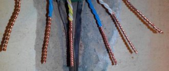
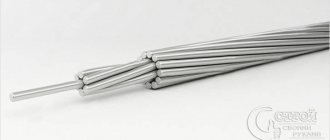
Stranded conductors are used where small radius bends are required when laying complex routes where single-core analogues cannot pass. This type of current conductors is convenient to install in cable ducts. Single-core wires are more difficult to bend in such conditions, force must be applied, and there is a risk of damage to the wire.
For your information. Marking APPV 3*2.5 means a wire with aluminum conductors, polyvinyl chloride insulation, flat, having a dividing base. The meaning of the marking is clarified in the reference literature.
In terms of structure, a cable consists of several individually insulated strands placed in a protective outer layer of dielectric material. The space between the cores and the shell is filled with paper tapes, plastic threads or cable yarn to prevent sticking. Additionally, the product can be reinforced with armor made of tapes or steel braiding to protect against mechanical damage.
Conductor cross-sectional area
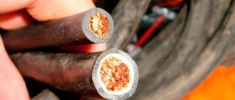
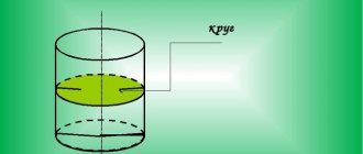
Calculation of voltage drop in a cable. In drawings, a section is an image of a figure formed by cutting a part with a plane. What is a cross section in electrical engineering? Applicable to electricity, considers the cross-section of a conductor at right angles to its longitudinal side. The cross-section of the core through which electrons pass is a circle and is measured in mm2. Important! The diameter of the core is often confused with its cross-section. To find out what cross-section the wire has, you need to determine the area of the resulting circle by calculating it using the formula.
Conductor cross section
Since the cross-section of the wire is a circle, the area is calculated using the formula:
S cr = π*R2, where:
- S cr. – area of the circle, mm2;
- π = 3.14;
- R – radius of the circle, mm.
Knowing the cross-sectional area of the core, its length and the resistivity of the material from which it is made, it is possible to calculate the resistance of the conductor to the electric current flowing through it.
Information. Considering that the radius is equal to 1/2 the diameter, the formula can be transformed for ease of use. It will look like Skr = π*D2/4 = 0.8 * D2. To calculate the cross-sectional area of a conductor, the diameter value is often used. An incorrectly selected wire diameter causes it to overheat and melt, which, in turn, can cause a fire in the electrical wiring.
Calculation of the cross-section of a stranded conductor
Stranded wire consists of several individual wires. Its cross section is calculated as follows:
- The indicator of the cross-sectional area of one core is found.
- Cable cores are recalculated.
- The quantity is multiplied by the cross-section of one core.
When connecting a stranded conductor, its ends are crimped with a special sleeve using crimping pliers.
Dependence of current, power and core cross-section
It is not enough to measure and calculate the cross-sectional area of the cable based on the diameter of the core. Before installing wiring or other types of electrical networks, it is also necessary to know the capacity of the cable products.
- When choosing a cable, you must be guided by several criteria:
- the strength of the electric current that the cable will pass;
- consumer power;
- current load exerted on the cable.
Power
The most important parameter during electrical installation work (in particular, cable laying) is throughput. The maximum power of electricity transmitted through it depends on the cross-section of the conductor. Therefore, it is extremely important to know the total power of the energy consumption sources that will be connected to the wire. Typically, manufacturers of household appliances, appliances and other electrical products indicate on the label and in the documentation accompanying them the maximum and average power consumption.
For example, a washing machine can consume electricity ranging from tens of W/h during rinsing mode to 2.7 kW/h when heating water.
Accordingly, a wire with a cross-section that is sufficient to transmit electricity of maximum power must be connected to it. If two or more consumers are connected to the cable, then the total power is determined by adding the limit values of each of them. The average power of all electrical appliances and lighting devices in an apartment rarely exceeds 7500 W for a single-phase network. Accordingly, the cable cross-sections in the electrical wiring must be selected to this value.
It is recommended to round the cross-section towards higher power due to a possible increase in power consumption in the future. Typically, the next largest cross-sectional area from the calculated value is taken. So, for a total power of 7.5 kW, it is necessary to use a copper cable with a core cross-section of 4 mm2, which is capable of transmitting about 8.3 kW. The cross-section of the conductor with an aluminum core in this case must be at least 6 mm2, passing a current power of 7.9 kW.
Calculation goals
Cross section of wires for lighting
It is necessary to calculate the parameters of the cross-sectional area of the conductor for several purposes:
- obtaining the required amount of electricity to power household appliances;
- eliminating overpayments for unused energy;
- wiring safety and fire prevention;
- the ability to connect high-power equipment to the network;
- prevention of melting of the insulating layer and short circuits;
- proper organization of the lighting system.
The optimal wire cross-section for lighting is 1.5 mm2 for the line, 4-6 mm2 for the input.
Features of self-calculation
Independent calculation of the longitudinal section is performed on a core without an insulating coating. A piece of insulation can be moved or removed on a piece purchased specifically for testing. First you need to determine the diameter and find the cross section using it. Several methods are used for the work.
Using a caliper
The method is justified if the parameters of a truncated or defective cable are measured. For example, VVG may be designated as 3x2.5, but in fact be 3x21. Calculations are made as follows:
- The insulating coating is removed from the conductor.
- The diameter is measured with a caliper. You will need to place the wire between the legs of the instrument and look at the scale markings. The integer value is on top, the decimal value is on the bottom.
- Based on the formula for finding the area of a circle S = π (D/2)2 or its simplified version S = 0.8 D², the cross section is determined.
- The diameter is 1.78 mm. Substituting the value into the expression and rounding the result to hundredths, we get 2.79 mm2.
For domestic purposes, you will need conductors with a cross section of 0.75; 1.5; 2.5 and 4 mm2.
Using a ruler and pencil
Calculation of PS using a ruler and pencil.
If you don't have a special meter, you can use a pencil and ruler. Operations are performed with the test image:
- An area of 5-10 cm is cleared of the insulating layer.
- The resulting wire is wound around a pencil. Full turns are laid tightly, there should be no space between them, the “tails” are directed up or down.
- Ultimately, a certain number of turns should be obtained; they need to be counted.
- The winding is applied to the ruler so that the zero division coincides with the first winding.
- The length of the segment is measured and divided by the number of turns. The resulting value is the diameter.
- For example, it turned out 11 turns, which occupy 7.5 mm. When dividing 7.5 by 11, 0.68 mm is the cable diameter. The cross section can be found using the formula.
The accuracy of the calculations is determined by the density and length of the winding.
Methods for determining wire cross-section step by step
There are several ways to measure the cross-section by core diameter. If the wire is single-core, then measurements will be made immediately on it, but one conductor must be untangled from the cable coil. After this, it is cleared of insulation so that only metal remains.
To calculate the area of a circle through the radius, use the formula: S = π × R2, where:
- π – constant equal to 3.14;
- R is the radius of the circle.
But, due to the fact that from a practical point of view it is much easier to calculate a diameter equal to two radii, the calculation formula will take the following form: S = π × (D/2)2. Depending on the methods for measuring the diameter, such methods for calculating the cross section are distinguished.
By diameter using a caliper or micrometer
The most relevant option to measure the diameter are instruments such as calipers and micrometers. These devices allow you to measure the diameter as accurately as possible. To do this you will need a wire and a micrometer.
To do this, latch B is moved to the open position. The micrometer handle is unscrewed to such a distance that the wire easily fits in the space between probes A. Then, using handle G, the device is twisted until the ratchet operates. After this, readings are recorded on all three scales at point B.
In this example, the diameter is 1.4 mm, therefore, to calculate the cross-section, you need S = 3.14 × 1.4 × 1.4 / 4 = 1.53 mm². The same procedure for determining the cross section can be performed using a caliper. The advantage of this method is the ability to measure any round conductor, even if it is already installed and used to power any electrical device. The main disadvantage of the method is the high cost of the devices; naturally, purchasing them for a couple of measurements is completely impractical.
By diameter using a pencil or pen
This method of determining the cross-section is based on the fact that the wire has the same diameter along its entire length. Take a regular pencil, pen or felt-tip pen and wrap the wire around it in a spiral. To eliminate the thickness of the insulation, it must be cut along its entire length. The rings should be placed as tightly as possible; the larger the space between the rings, the lower the accuracy.
Since all wires have the same thickness, to determine the diameter of the copper wires, measure the length of the entire winding and divide by the number of turns. In this example, D = 15 mm / 15 turns = 1 mm, respectively, using the same calculation formula, we obtain a section S = 3.14 × 1 × 1 / 4 = 0.78 mm². Note that the more turns you make, the more accurately you determine the cross-section.
It is worth noting that the advantage of this method is that only available means can be used to determine the cross-section. The disadvantage is low accuracy and the ability to wind only thin conductors. In the example, a relatively thin wire was used, but the distance between the turns is already visible. Because of which the accuracy leaves much to be desired, it goes without saying that aluminum wire cannot be bent in this way.
By diameter using a ruler
Let’s immediately make a reservation that for measuring with a ruler you can only take a relatively thick wire; the smaller the thickness, the lower the accuracy. The diameter of the vein can be determined by thread or paper; the second option is the most preferable, as it gives greater accuracy.
Tear off a small strip and fold it over on one side. Thinner paper is preferable, so there is no need to fold the sheet several times. Then the paper is applied to the wire and wrapped around the circumference until the strip touches. At the point of contact, it is bent a second time and applied to the ruler for measurement.
Using the resulting circumference L, the vein diameter D = L / 2 π is found, and the cross section is calculated as shown earlier. This method of determining the cross-section is well suited for large aluminum conductors. But the accuracy in this method is the lowest.
By diameter using ready-made tables
This method is suitable for standard gauge wires. For example, you have already determined the diameter using one of the above methods. Then you use the table to determine the section.
Table 1: determination of cross section based on wire diameter:
Diameter and cross-section of wires in the table
At first glance, the use of such tables is not advisable, since the conductor tag indicates its main parameters, however, there are certain subtleties here too. The fact is that the parameters declared by the manufacturer do not always correspond to reality, but the parameters given in the table are absolutely objective.
If, when measuring the diameter, the result given in the table does not differ significantly from the declared one, then you are dealing with a high-quality wire, but there are cases when the cross-sectional area does not correspond to the measured diameter of the wire, in this case, using the table will allow you to avoid purchasing a low-quality cable.
Expert opinion
It-Technology, Electrical power and electronics specialist
Ask questions to the “Specialist for modernization of energy generation systems”
Wire cross-section and diameter: table | Advice from experts In order to avoid such unpleasant situations, it would be a good idea to measure the diameter of the core yourself before purchasing a wire and make sure that the declared characteristics correspond to the actual ones. Ask, I'm in touch!
Determining the wire cross-section of outlet lines
When determining the wire diameter for room wiring, consider the maximum load of consumers that can be turned on at the same time. Based on this power, the cross-section of the main lines that go from the meter and input circuit breakers to the distribution boxes is selected. These are the areas that will bear the total load of all connected consumers. Choose a wire with copper conductors of at least 6 mm2.
Branch conductors from distribution boxes to sockets are selected individually for each room. This takes into account household electrical appliances that can be connected to an outlet. The cross-section of the cores is selected with a margin of one order of magnitude. This is in case there is a need to power some kind of construction tool from an outlet: a hammer drill, a welding inverter.
If the total power of consumers in the room is 4 kW, then the conductor with a copper core feeding the outlet should have a cross-section of 2.5 mm².
Attention! The cross-section of the conductor must allow it to withstand the current load and not overheat during operation of household appliances. In practice, the device with the highest power is determined and the appropriate wire diameter is selected relative to the characteristics of the device.
As a result, it turns out that the outlet conductor with copper conductors for each socket will have a cross-section of 2.5 mm2. The main wire for wiring is taken with a cross-section of 6 mm². It should be taken into account that the entire electrical wiring circuit is carried out with wires having cores of the same material. Copper and aluminum strands cannot be twisted together.
How to correctly determine the wire cross-section
We're done with the theory. It’s time to move on to the main question of the topic - how to determine the required cross-section of the current-carrying conductor for various operating conditions of electrical wiring.
There are several options for finding the desired result.
You can choose the one that seems most convenient or suitable for a particular case.
Calculation using permissible current density
From everything stated above, it should already be clear that the main limiter when choosing the required cross-section is resistive heating of the conductors, which can lead to melting of the insulation, short circuits, overheating of surrounding materials, up to the possibility of spontaneous combustion.
That is, the selected wire cross-section should exclude such phenomena.
Carrying out accurate thermal calculations is a very difficult matter. But experts have already done a lot in this regard, so you can take advantage of their work.
In particular, they calculated a safe current density that does not cause dangerous heating of the conductor to temperatures that could cause melting of the most common PVC or PE insulation nowadays.
So, for conductors located at conventional room temperature (+20℃), this current density is:
| Wire material | Optimal current density, A/mm² | |
| Wiring Location | Open | Closed |
| Aluminum | 3.5 | 3 |
| Copper | 5 | 4 |
Let’s immediately clarify the difference between open and closed wiring.
- Open is not so common. It is laid along walls or ceilings using clamps or insulators; it can be airborne - self-supporting or held by a supporting cable. Open wiring also includes power cords and extension cords, unless, of course, they are wound on coils, bobbins, etc.
- Everything else, in fact, is closed wiring: located in cable ducts, ducts or corrugated pipes, embedded in walls, laid in the ground, etc. In other words, in any conditions where there is no normal heat dissipation. Based on this criterion, closed wiring should also include those areas that are located in distribution boards and installation boxes - there is no normal heat exchange here either.
It was not for nothing that it was stated above that the indicated indicators are valid for room temperature. It happens that wiring has to be laid in rooms with a special temperature regime, that is, in which heating is maintained above normal (dressing rooms, dryers, greenhouses, etc.) In this case, adjustments are made to the value of the permissible current density - a coefficient of 0.9 per every 10 degrees temperature above +20 ℃.
For example, what current density should you focus on if you plan to lay copper wiring in a cable duct to connect a heating element in a dryer in which the temperature will be maintained at +50 ℃?
According to the table, the current density G for closed copper wiring is 4 A/mm² .
The difference between the temperature norm and the planned regime is
50 – 20 = 30 ℃.
That is, the reduction factor must be taken into account three times. But this means not 0.9 × 3, but 0.9³:
G = 4 × 0.9 × 0.9 × 0.9 = 4 × 0.9³ = 4 × 0.729 = 2.92 A/mm²
You will have to focus on this density indicator to create wiring that is safe under these conditions.
One more example. Let's say, in the conditions already discussed, wiring is laid to connect two heaters with a power of 750 watts each.
The total power load per line is:
P = 750 + 750 = 1500 W
Let's recalculate it into the required current at a voltage of 220 volts:
I = P / U = 1500 / 220 = 6.8 A
We calculated the normal current density for such operating conditions to be 2.92 A/mm². That is, it costs nothing to calculate the cross-section of the copper core that will ensure a safe density:
S = I / G = 6.8 / 2.92 = 2.33 mm²
Naturally, the resulting value is reduced to the nearest one, rounded up. That is, for laying wiring under the specified conditions, a copper wire with a cross section of 2.5 mm² .
In principle, the same principle can be used to carry out calculations for any other premises. Including for lines to which it is planned to connect several electrical appliances of varying power.
In this case, the total power of the line can be calculated as follows:
Σ P = ( P₁ + Р₂ + … + Рₙ) × Кс × Кз
In brackets are the powers of electrical appliances connected to the line, from 1 to n.
Kc is the so-called demand coefficient. It is unlikely that all devices connected in the line will work simultaneously. That is, this coefficient takes into account the probability of their simultaneous inclusion.
Calculating this coefficient is not an easy task, as it takes into account many nuances. But since our publication is intended for amateur electricians, whose work is probably limited to their small residential properties, we can simplify the task. Specifically: with two devices, we leave the coefficient equal to one. At three ÷ four – 0.8. Five ÷ six – 0.75. It is unlikely that you will encounter a larger number of consumers on the line in a house or apartment, but just in case, if suddenly... - the coefficient is 0.7.
Кз – safety factor. The value is optional. But a prudent owner can think ahead that, perhaps, in a year or two, an additional load will have to be connected to the same line, which can only be guessed at for now. So it makes sense to immediately lay down a reserve by taking a coefficient, for example, from 1.5 to 2.0. But, we repeat, the matter is voluntary, and this coefficient can be completely excluded from the calculations.
Another important point. The actual power of an electrical device may be higher than the nominal power indicated in the passport. This is related to the concepts of active and reactive power.
We won’t go into too much detail about the physics of this phenomenon, let’s just say that the total power for some types of load is calculated using the formula:
Pп = Pn / cos φ
Pп — total power;
Pn is the rated power indicated in the passport;
cos φ - power factor equal to the cosine of the angle φ - phase displacement of current and voltage.
This displacement is typical for devices with a powerful electric drive, with a high inductive load (transformers, chokes). cos φ value for such equipment is also indicated in the product passport.
Values of rated power and cos φ on the nameplate of an asynchronous motor
In everyday life, such devices are rarely found, but still, if a line is installed, say, to power a powerful pump, compressor, electric motor, or for a welding station, it is better not to skimp on this indicator.
Now you can try to make a full calculation, taking into account everything said above. For this, the reader is offered an online calculator.
You must enter the requested data in the program input fields:
- What wiring will be used: copper or aluminum, open or closed.
- Voltage in the planned line.
- If a specific temperature regime is expected in the room, then this should be indicated - choose from the proposed options. The temperature in the room below +25℃ will be considered normal - it is listed first and is taken into account by default.
- Next, the power of the load planned for connection is indicated. There are up to 6 different units - this is usually enough for domestic conditions. Moreover, if the field is not filled in, then the power is considered equal to zero, that is, the field is not taken into account.
The last two fields allow you to take into account the load with a reactive power component, if any. To do this, in addition to the nominal value, you must also indicate the cos φ value. By default, cos φ = 0 , that is, as for a regular active load.
- Depending on the number of devices connected to the line, the algorithm automatically takes into account the demand coefficient.
- Finally, the user can reserve power by increasing the safety factor, from 1 to 2 in increments of 0.1.
The calculation result will be given in square millimeters of the cross-section of the wire (cable) core with an accuracy of one hundredth. Naturally, after this you will have to round up to the nearest standard size.
Calculator for calculating the cross-sectional area of the current-carrying core of a cable or wire
Finding the required cable cross-section using tables
Not everyone and not always like to do their own calculations. Such users can be recommended to use tables.
Essentially, these are the same calculations performed by specialists using the given formulas. But only for convenience, their results are summarized in a tabular presentation.
For example, a table for determining the permissible cross-section (and corresponding diameter) of the core based on the load power and (or) current value for an alternating voltage of 220 volts (OP and ZP - open and closed wiring, respectively):
| Load power, W | Current, A | COPPER | ALUMINUM | ||||||
| OP | Salary | OP | Salary | ||||||
| S, mm² | d, mm | S, mm² | d, mm | S, mm² | d, mm | S, mm² | d, mm | ||
| 100 | 0,43 | 0,09 | 0,33 | 0,11 | 0,37 | 0,12 | 0,40 | 0,14 | 0,43 |
| 200 | 0.87 | 0,17 | 0,47 | 0,22 | 0,53 | 0,25 | 0,56 | 0.29 | 0,61 |
| 300 | 1,30 | 0,26 | 0,58 | 0,33 | 0,64 | 0,37 | 0,69 | 0,43 | 0,74 |
| 400 | 1,74 | 0,35 | 0,67 | 0,43 | 0,74 | 0,50 | 0,80 | 0,58 | 0,86 |
| 500 | 2.17 | 0,43 | 0,74 | 0,54 | 0,83 | 0,62 | 0,89 | 0.72 | 0,96 |
| 750 | 3,26 | 0,65 | 0,91 | 0,82 | 1,02 | 0,93 | 1,09 | 1,09 | 1,18 |
| 1000 | 4,35 | 0,87 | 1,05 | 1,09 | 1,18 | 1,24 | 1,26 | 1,45 | 1,36 |
| 1500 | 6,52 | 1,30 | 1,29 | 1,63 | 1,44 | 1,86 | 1,54 | 2,17 | 1,66 |
| 2000 | 8,70 | 1,74 | 1,49 | 2,17 | 1,66 | 2,48 | 1,78 | 2,90 | 1,92 |
| 2500 | 10,87 | 2,17 | 1,66 | 2,72 | 1,86 | 3,11 | 1,99 | 3.62 | 2,15 |
| 3000 | 13.04 | 2,61 | 1,82 | 3,26 | 2,04 | 3,73 | 2.18 | 4,35 | 2,35 |
| 3500 | 15,22 | 3,04 | 1,97 | 3,80 | 2,20 | 4,35 | 2,35 | 5.07 | 2,54 |
| 4000 | 17.39 | 3,48 | 2,10 | 4,35 | 2,35 | 4.97 | 2.52 | 5,80 | 2.72 |
| 4500 | 19,57 | 3,91 | 2,23 | 4,89 | 2,50 | 5,59 | 2,67 | 6,52 | 2,88 |
| 5000 | 21,74 | 4,35 | 2,35 | 5,43 | 2,63_ | 6,21 | 2,81 | 7.25 | 3,04 |
| 6000 | 26.09 | 5,22 | 2,58 | 6,52 | 2,88 | 7,45 | 3,08 | 8,70 | 3,33 |
| ]000 | 30,43 | 6,09 | 2,78 | 7,61 | 3,11 | 8,70 | 3,33 | 10,14 | 3,59 |
| 8000 | 34.78 | 6,96 | 2,98 | 8,70 | 3,33 | 9,94 | 3,56 | 11,59 | 3,84 |
| 9000 | 39.13 | 7,83 | 3,16 | 9,78 | 3,53 | 11,18 | 3,77 | 13,04 | 4,08 |
| 10000 | 43,48 | 8,70 | 3,33 | 10,87 | 3,72 | 12,42 | 3,98 | 14.49 | 4,30 |
Slightly different tables are more common. They show the standard cross-sections of manufactured cable products and the corresponding permissible values of current and load power.
Here is a table for cables with copper conductors :
| Cross-section of current-carrying core, mm² | Voltage 220 V | Voltage 380 V | ||
| I, A | P, kW | I, A | P, kW | |
| 1.5 | 19 | 4.1 | 16 | 10.5 |
| 2.5 | 27 | 5.9 | 25 | 16.5 |
| 4 | 38 | 8.3 | 30 | 19.8 |
| 6 | 46 | 10.1 | 40 | 26.4 |
| 10 | 70 | 15.4 | 50 | 33 |
| 16 | 85 | 18.7 | 75 | 49.5 |
| 25 | 115 | 25.3 | 90 | 59.4 |
| 35 | 135 | 29.7 | 115 | 75.9 |
| 50 | 175 | 38.5 | 145 | 95.7 |
| 70 | 215 | 47.3 | 180 | 118.8 |
| 95 | 260 | 57.2 | 220 | 145.2 |
| 120 | 300 | 66 | 260 | 171.6 |
A similar table is for cables with aluminum conductors:
| Cross-section of current-carrying core, mm² | Voltage 220 V | Voltage 380 V | ||
| I, A | P, kW | I, A | P, kW | |
| 2.5 | 20 | 4,4 | 19 | 12,5 |
| 4 | 28 | 6,1 | 23 | 15,1 |
| 6 | 36 | 7,9 | 30 | 19,8 |
| 10 | 50 | 11,0 | 39 | 25,7 |
| 16 | 60 | 13,2 | 55 | 36,3 |
| 25 | 85 | 18,7 | 70 | 46,2 |
| 35 | 100 | 22,0 | 85 | 56,1 |
| 50 | 135 | 29,7 | 110 | 72,6 |
| 70 | 165 | 36,3 | 140 | 92,4 |
| 95 | 200 | 44,0 | 170 | 112,2 |
| 120 | 230 | 50,6 | 200 | 132,2 |
There are tables that immediately take into account the number of current-carrying conductors in one cable channel (duct, pipe, etc.). That is, the mutual thermal influence is taken into account under conditions of limited heat removal.
Such a table for copper cables is shown below.
(Abbreviations: OZh - single-core, DZh - two-core, TZh - three-core).
| Cross-section of current-carrying core, mm² | Current, A, for wires laid | |||||
| open | in one cable channel | |||||
| 2×coolant | 3×coolant | 4×coolant | 1×J | 1×TJ | ||
| 0.5 | 11 | — | — | — | — | — |
| 0.75 | 15 | — | — | — | — | — |
| 1 | 17 | 16 | 15 | 14 | 15 | 14 |
| 1.2 | 20 | 18 | 16 | 15 | 16 | 14.5 |
| 1.5 | 23 | 19 | 17 | 16 | 18 | 15 |
| 2 | 26 | 24 | 22 | 20 | 23 | 19 |
| 2.5 | 30 | 27 | 25 | 25 | 25 | 21 |
| 3 | 34 | 32 | 28 | 26 | 28 | 24 |
| 4 | 41 | 38 | 35 | 30 | 32 | 27 |
| 5 | 46 | 42 | 39 | 34 | 37 | 31 |
| 6 | 50 | 46 | 42 | 40 | 40 | 34 |
| 8 | 62 | 54 | 51 | 46 | 48 | 43 |
| 10 | 80 | 70 | 60 | 50 | 55 | 50 |
| 16 | 100 | 85 | 80 | 75 | 80 | 70 |
| 25 | 140 | 115 | 100 | 90 | 100 | 85 |
| 35 | 170 | 135 | 125 | 115 | 125 | 100 |
| 50 | 215 | 185 | 170 | 150 | 160 | 135 |
| 70 | 270 | 225 | 210 | 185 | 195 | 175 |
| 95 | 330 | 275 | 255 | 225 | 245 | 215 |
| 120 | 385 | 315 | 290 | 260 | 295 | 250 |
A similar table is for cables with aluminum wires:
| Cross-section of current-carrying core, mm² | Current, A, for wires laid | |||||
| open | in one cable channel | |||||
| 2×coolant | 3×coolant | 4×coolant | 1×J | 1×TJ | ||
| 2 | 21 | 19 | 18 | 15 | 17 | 14 |
| 2.5 | 24 | 20 | 19 | 19 | 19 | 16 |
| 3 | 27 | 24 | 22 | 21 | 22 | 18 |
| 4 | 32 | 28 | 28 | 23 | 25 | 21 |
| 5 | 36 | 32 | 30 | 27 | 28 | 24 |
| 6 | 39 | 36 | 32 | 30 | 31 | 26 |
| 8 | 46 | 43 | 40 | 37 | 38 | 32 |
| 10 | 60 | 50 | 47 | 39 | 42 | 38 |
| 16 | 75 | 60 | 60 | 55 | 60 | 55 |
| 25 | 105 | 85 | 80 | 70 | 75 | 65 |
| 35 | 130 | 100 | 95 | 85 | 95 | 75 |
| 50 | 165 | 140 | 130 | 120 | 125 | 105 |
| 70 | 210 | 175 | 165 | 140 | 150 | 135 |
| 95 | 255 | 215 | 200 | 175 | 190 | 165 |
| 120 | 295 | 245 | 220 | 200 | 230 | 190 |
If desired, you can find tables of a narrower specialization, for example, for overhead laying of wires or for underground, and also taking into account the heat-dissipating qualities of a particular soil. But we will not overload this publication with them - it is still intended for novice electricians who, in their debut, perform simpler tasks.
Some craftsmen even recommend taking into account a simplified version of the table of cross-sections of wires and cables used for home wiring. Like this:
| Cross-section of copper wire, mm² (aluminum in brackets) | Maximum current under continuous load, A | Maximum load power. kW | Rated current of the circuit breaker, A | Maximum circuit breaker protection current, A | Scope of application in home (apartment) conditions |
| 1,5 (2,5) | 19 | 4.1 | 10 | 16 | lighting, alarm devices |
| 2,5 (4,0) | 27 | 5.9 | 16 | 25 | socket blocks, floor heating systems |
| 4,0 (6,0) | 38 | 8.3 | 25 | 32 | powerful climate control equipment, water heaters, washing machines and dishwashers |
| 6,0 (10,0) | 46 | 10.1 | 32 | 40 | electric stoves and electric ovens |
| 10,0 (16,0) | 70 | 15.4 | 50 | 63 | power input lines |
By and large, this is how it usually turns out. But finally, let's consider one more important nuance.
Tables for selecting a suitable conductor
A convenient and practical option for selecting the desired wire (cable) is to use special tables that indicate the diameters and cross-sections relative to the power and/or currents carried.
Having such a table at hand is an easy and simple way to quickly determine the conductor for the required electrical installation. Determining the required values using a classic table is one of the most convenient ways to select the required conductor during installation work. Considering that traditional conductors for electrical installations are products with copper or aluminum conductors, there are tables for both types of metals.
Also, tabular data often presents values for voltages of 220 volts and 380 volts. Plus, the installation conditions are taken into account - closed or open wiring. In fact, it turns out that one sheet of paper or a picture loaded into a smartphone contains voluminous technical information that allows you to do without the above-mentioned mathematical (linear) calculations.
Moreover, many manufacturers of cable products, in order to make it easier for the buyer to choose the right conductor, for example, for installing sockets, offer a table in which all the necessary values are entered. All that remains is to determine what load is planned for a specific electrical point and how the installation will be performed, and based on this information, select the correct wire with copper or aluminum conductors.
Which cable to choose for apartment wiring
Despite the cheapness of aluminum conductors, it is better to avoid using them. The reason is the low reliability of the contacts through which currents will pass. The second reason is the mismatch of the wire cross-section with the power of modern household appliances. Copper cable is reliable and has a long service life.
In apartments and houses it is allowed to use wire marked:
- PUNP is a flat conductor with copper conductors in a PVC sheath. Designed for a nominal voltage of 250 V at a frequency of 50 Hz.
- VVG/VVGng – flat cables made of copper with double PVC coating. They are used inside and outside buildings and are not subject to fire. They come with 2, 3 and 4 cores.
- NYM - copper wire for internal single line. It has an insulating PVC sheath and outer covering, conductors with and without grounding.
When choosing the number of cores, you will need to take into account the conductivity per unit cross-section. In this case, it is better to make the apartment network from a single-core wire, the thickness of which is greater. Multicore elements can be bent many times and electrical appliances can be connected to them. Only a cable with thin cores will be of high quality.
The correct cross-section of conductors, taking into account the power of the equipment and the type of network are important factors when organizing an electrical line. The cable diameter can be calculated independently in several ways. Based on these readings, it is easy to determine the cross-section of the cores using formulas or using a table.
What is the cross section measured in?
After determining the diameter using the indicated methods, the cross-sectional area can be determined using a formula or a special table. It is measured in square millimeters. This unit of measurement is derived according to the Unified International System of Measurements.
You may be interested in this The danger of step tension
Unit of measurement
At the same time, the cut of the vein was always round.
